Harvey Performance Company
  • About Us
    • Company Overview
    • Our Unique Strengths
    • Our Partners
    • Our History
    • Our Locations
    • Sustainability
    • Giving Back
      • Giving Back
      • One Tree Planted
    • News
      • News
      • Press
  • Our Brands
    • Harvey Tool
    • Helical Solutions
    • Micro 100
    • Titan USA
    • CoreHog
    • Valor Holemaking
    • ATA Air Tools
    • ATA SGSPRO
    • Garryson
    • Industrial Tooling Corporation (ITC)
    • Karnasch
    • Van Hoorn Carbide
  • Products
    • Milling
    • Drilling
    • Grinding
    • Micro Tools
    • Sinking
    • Sawing
    • Composite Tools
    • Threading
    • Turning
    • Beveling
    • Reaming
    • Air Tools
  • Solutions
    • Aerospace
    • Automotive
    • Defense
    • Energy
    • Foundries
    • Marine
    • Medical
    • Mold & Die
    • Oil & Gas
    • Power Generation
    • Rail
  • Resources
    • CAM & TDM Tool Libraries
    • Machining Advisor Pro
    • In the Loupe Blog
    • Webinars
  • Careers
  • Contact Us
  • Menu Menu
  • Link to LinkedIn
  • Link to Facebook

Tips for Machining Gummy Materials

May 15, 2018/11 Comments/in CNC Machining, Helical Solutions, Tech Tips/by Harvey Performance Company

Machinists face many problems and challenges when manufacturing gummy materials. These types of materials include low carbon steels, stainless steels, nickel alloys, titanium, copper, and metals with high chromium content. Gummy materials have a tendency to produce long, stringy chips, and are prone to creating built-up edge. These common problems can impact surface finish, tool life, and part tolerances.
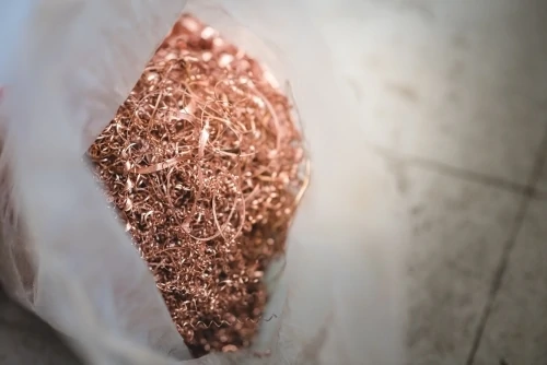
bag of copper chips from cnc machining

Continuous Chip With a Built-Up Edge

Continuous chips are long, ribbon-like chips that are formed when the tool cuts through a material, separating chips along the shear plane created by the tool’s cutting edge. These chips slide up the tool face at a constant flow to create a long and stringy chip. The high temperatures, pressures, and friction produced when cutting are all factors that lead to the sticky chips that adhere to the cutting edge. When this built up edge becomes large enough, it can break off leaving behind some excess material on the workpiece, or gouge the workpiece leaving a poor surface finish.

Coolant

Using large amounts of coolant can help with temperature control and chip evacuation while machining gummy materials. Temperature is a big driving force behind built-up edge. The higher the temperature gets, the easier and faster a built-up edge can form. Coolant will keep local temperatures lower and can prevent the material from work hardening and galling. Long, stringy chips have the potential to “nest” around the tool and cause tool failure. Coolant will help break these chips into smaller pieces and move them away from the cutting action by flash cooling them, resulting in fracturing of the chip into smaller pieces. Coolant should be applied directly to the contact area of the tool and workpiece to have the maximum effect.

Tool Engagement

Running Parameters

The tool should be constantly fed into the workpiece. Allowing the tool to dwell can cause work hardening and increase the chance of galling and built up edge. A combination of higher feed rates and lower speeds should also be used to keep material removal rates at a reasonable level. An increase in feed rates will raise the temperature less than an increase in speed. This relates to chip thinning and the ability of a tool to cut the material rather than rub against it.

Climb Milling

Climb milling is the preferred method as it directs more heat into the chip than the tool. Using climb milling, the largest chip cross section is created first, allowing the tool to cut through the material much easier. The heat generated from friction when the tool penetrates the workpiece is transferred to the chip rather than the tool because the thickest part of the chip is able to hold more heat than the thinnest.
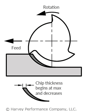
infographic showcasing the rotation and movement of a cutting tool in climb milling

Initial Workpiece Engagement

Sudden, large changes in force, like when a tool initially engages a workpiece, have a negative impact on tool life. Using an arc-in tool path to initially engage the material allows for increased stability with a gradual increase in cutting forces and heat. A gradual tool entry such as this is always the preferred method over an abrupt straight entry.

Tool Selection

A tool with a sharp and robust cutting edge should be selected to machine gummy materials. Helical has tooling specifically designed for Titanium and Stainless Steel to make your tool selection process easy.

Additionally, choosing a tool with the correct coating for the material you are machining will help to protect the cutting edge and result in a far lower chance of built up edge or galling than an uncoated tool. A tool with a higher flute count can spread tool wear out over multiple cutting edges, extending tool life. Tool wear is not always linear in gummy materials; as soon as a little bit of wear appears, tool failure will happen relatively quickly. Changing the tool at the first sign of wear may be necessary to ensure that parts are not scrapped.
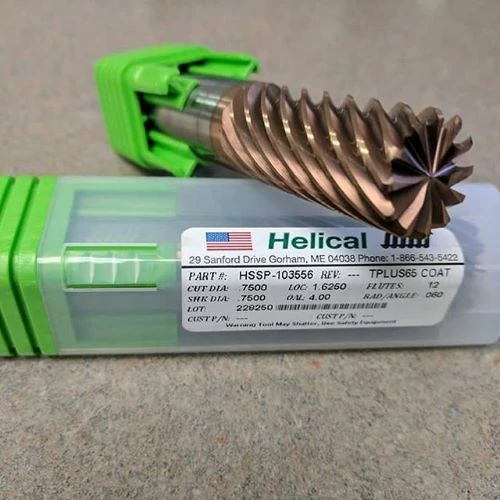
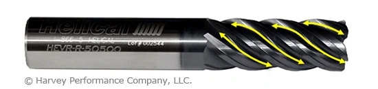
7 flute end mill for gummy materials

Gummy Materials Summarized

Every material machines somewhat differently, but understanding what is happening when the tool cuts the workpiece and how this affects tool life and finish will go a long way to successfully completing any job.  Built-up edge and excess heat can be minimized by selecting the correct tool and coating for the material, and following the tips and techniques mentioned above. Finally, be sure to check your machine’s runout and ensure maximum rigidity prior to beginning your machining operation.
https://www.harveyperformance.com/wp-content/uploads/2018/05/Featured-Image-Gummy-Materials-IMG.jpg 525 1400 Harvey Performance Company http://www.harveyperformance.com/wp-content/uploads/2018/08/Logo_HarveyPerformanceCompany-4.png Harvey Performance Company2018-05-15 16:47:142023-10-24 10:21:46Tips for Machining Gummy Materials

Attacking Aluminum: a Machining Guide

April 24, 2018/11 Comments/in Aluminum, CNC Machining, Helical Solutions, Material Specific, Milling, Tech Tips/by Harvey Performance Company

Aluminum is one of the most commonly machined materials, as most forms of the material feature excellent machinability, and is thus a commonly used material in manufacturing. Because of this, the competition for aluminum machining can be intense. Understanding the basics behind tool selection, running parameters, and advanced milling techniques for aluminum can help machinists earn a competitive advantage.

Material Properties

Aluminum is a highly formable, workable, lightweight material. Parts made from this material can be found in nearly every industry. Additionally, Aluminum has become a popular choice for prototypes due to its low-cost and flexibility.

Aluminum is available in two basic forms: Cast and Wrought. Wrought Aluminum is typically stronger, more expensive, and contains a lower percentage of outside elements in its alloys. Wrought Aluminum is also more heat-resistant than Cast and has a higher level of machinability.

Cast Aluminum has less tensile strength but with a higher flexibility. It costs less, and has higher percentages of outside elements (silicon, magnesium, etc.) in its alloys, making it more abrasive than Wrought.

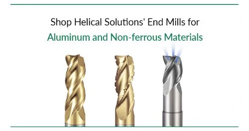
Shop Helical Solutions’ End Mills for Aluminum & Non-ferrous Materials

Tool Geometry

There are a few coating options available for Aluminum tooling, including the popular gold-colored ZrN (Zirconium Nitride) and the lesser known but highly effective TiB2 (Titanium Diboride). Uncoated tooling can also provide solid machining performance. However, the real key to high performance machining in Aluminum is knowing the proper flute count and helix angle required for your operation.

Flute Count

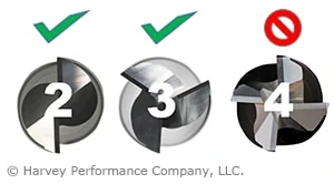
End mills for aluminum are often available in either 2 flute or 3 flute styles. With higher flute counts, it would become difficult to evacuate chips effectively at the high speeds at which you can run in aluminum. This is because aluminum alloys leave a large chip, and chip valleys become smaller with each additional flute on an end mill.

2, 3, and 4 flute count for aluminum

Traditionally, 2 flute end mills have been the preferred choice for Aluminum. However, 3 flute end mills have proven to be more successful in many finishing operations, and with the right parameters they can also work successfully as roughers. While much of the debate between 2 and 3 flute end mills for Aluminum boils down to personal preference, the operation, rigidity, and desired material removal rates can also have an effect on tool selection.

Helix Angles

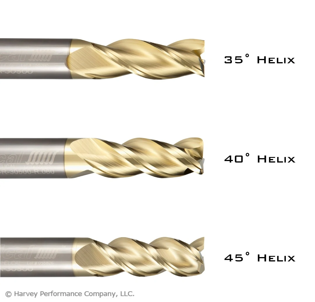
The helix angle of a tool is measured by the angle formed between the centerline of the tool and a straight line tangent along the cutting edge. Cutting tools for aluminum typically feature higher helix angles than standard end mills. Specialized helix angles for Aluminum are typically either 35°, 40°, or 45°. Variable helix tools are also available and make a great choice for reducing chatter and harmonics while also increasing material removal rates.

35, 40, and 45 degree helix choices for Aluminum Machining end mills

A helix angle of 35° or 40° is a good choice for traditional roughing and slotting applications. A 45° helix angle is the preferred choice for finishing, but also for High Efficiency Milling toolpaths as the high helix angle wraps around the tool faster and makes for a more aggressive cut.

Tooling Options

When machining aluminum, standard 2 or 3 flute tools will often get the job done. However, for certain applications and machine setups there are some more tooling options to consider for even better performance.

helical solutions end mills for aluminum and non-ferrous materials ad

Chipbreaker Tooling

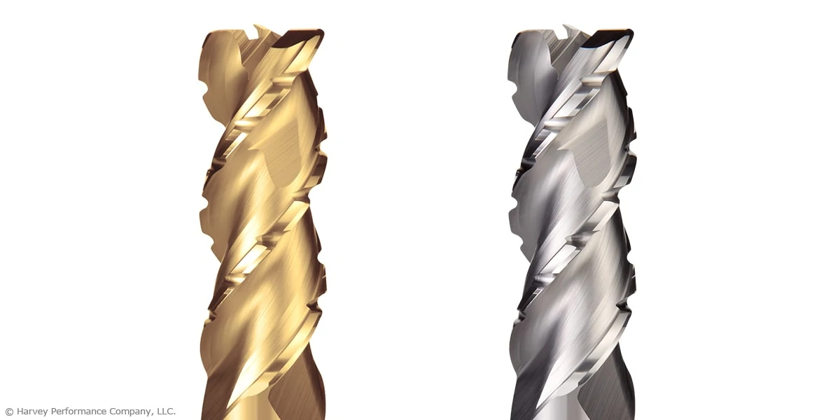
One of the most important things to consider when machining aluminum (and many other materials) is effective chip evacuation. Standard 2-3 flute end mills running at recommended speeds and feeds and proper chip loads can evacuate chips fairly well. However, 3 flute chipbreaker tooling can run at increased speed and feed rates for even better performance. The unique offset chip breaker geometry creates smaller chips for optimal evacuation while still leaving a semi-finished surface.

two Chipbreaker Aluminum end mills

These tools are excellent for more advanced toolpaths like High Efficiency Milling, which is another important tool for a successful aluminum machining experience.

High Balance End Mills

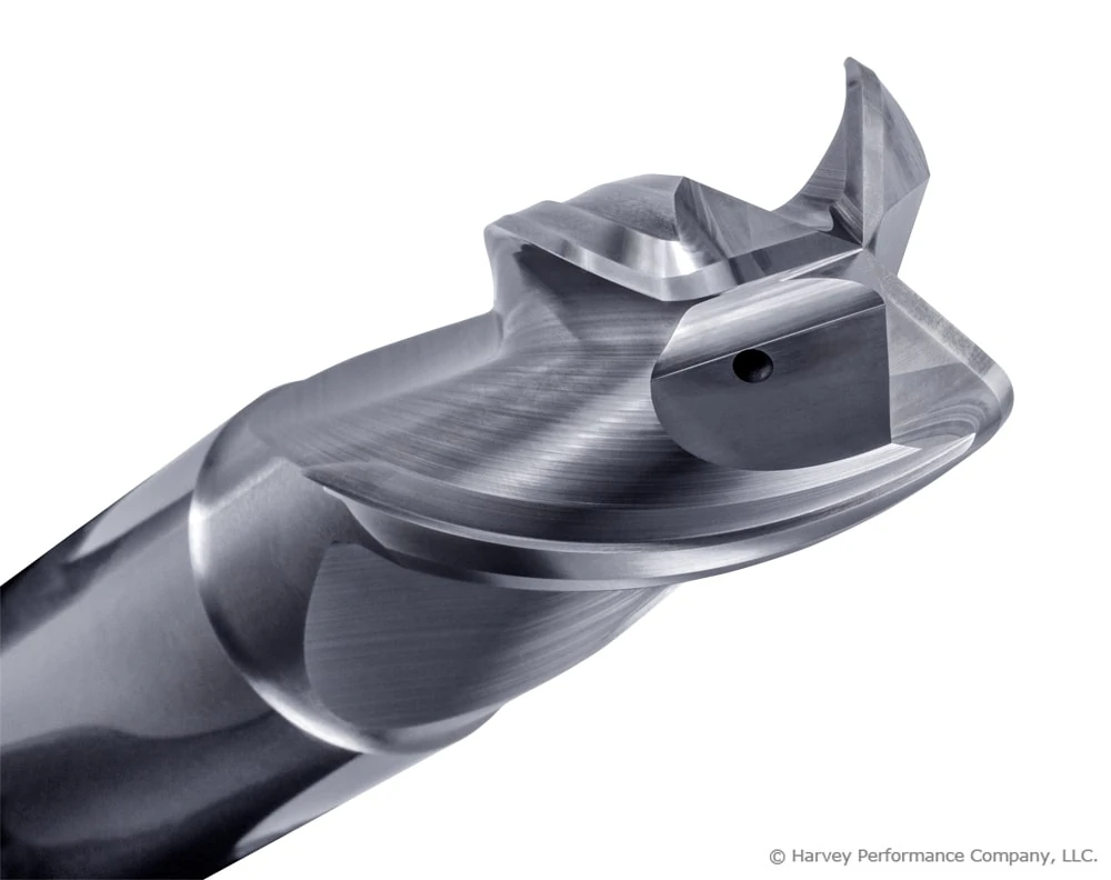
High balance end mills are designed to significantly increase performance in highly balanced machining centers capable of elevated RPMs and feed rates. These tools are precision balanced specifically for high velocity machining in aluminum (up to 33,000 RPM).

Zoomed in image of helical solutions High Balance coolant through Tool for Aluminum

Helical Solutions offers high balance tooling in standard 2 flute styles, as well as coolant-through 3 flute styles for reduced heat, enhanced chip evacuation, and increased material removal rates. These tools, like the chipbreakers, are also an excellent choice for High Efficiency Milling toolpaths.

Running Parameters

Setting the right parameters for aluminum applications is vital to optimizing productivity and achieving better machining results. Since aluminum is an easier material to machine, pushing your machine to its limits and getting the most out of your tool is vital to stay ahead of the competition and keep winning business.

While there are many factors that go into the parameters for every job, there are some general guidelines to follow when machining aluminum. For cast aluminum alloys (i.e. 308, 356, 380), a surface footage of 500-1000 SFM is recommended, with RPMs varying based on cutter diameter. The basic calculation to find a starting point for RPMs would be (3.82 x SFM) / Diameter.

In wrought aluminum alloys (i.e. 2024, 6061, 7075), a surface footage of 800-1500 SFM is recommended, with the same calculation being used to find a starting point for RPMs.

High Efficiency Milling

High Efficiency Milling, commonly known as HEM, is a strategy that is rapidly gaining popularity in the manufacturing industry. Many CAM programs are now including HEM toolpaths, and while virtually any machine can perform HEM, the CNC controller must feature a fast processor to keep up with the additional lines of code. A great example of High Efficiency Milling toolpaths in Aluminum can be seen below.

At its core, HEM is a roughing technique that utilizes a low Radial Depth of Cut (RDOC) and a high Axial Depth of Cut (ADOC) to take full advantage of the cutting edge of the tool. To learn more about how High Efficiency Milling can increase your efficiency, extend your tool life to keep costs down, and get greater performance for aluminum (and other materials), click here to download the HEM Guidebook.

In Summary

Aluminum is a versatile material with a high level of machinability, but it should not be overlooked. Understanding the best ways to tackle it is important for achieving the desired results. Optimizing your tool crib, machine setups, and toolpaths for aluminum is essential to stay ahead of the competition and make your shop more efficient.

https://www.harveyperformance.com/wp-content/uploads/2018/04/Featured-Image-Attacking-Aluminum-IMG.jpg 525 1400 Harvey Performance Company http://www.harveyperformance.com/wp-content/uploads/2018/08/Logo_HarveyPerformanceCompany-4.png Harvey Performance Company2018-04-24 16:00:122024-11-07 16:32:38Attacking Aluminum: a Machining Guide

Optimize Roughing With Chipbreaker Tooling

October 24, 2017/8 Comments/in CNC Machining, Helical Solutions, Tool Information Guides, Tool Selection, Troubleshooting Tips/by Harvey Performance Company

What is Chipbreaker Tooling?

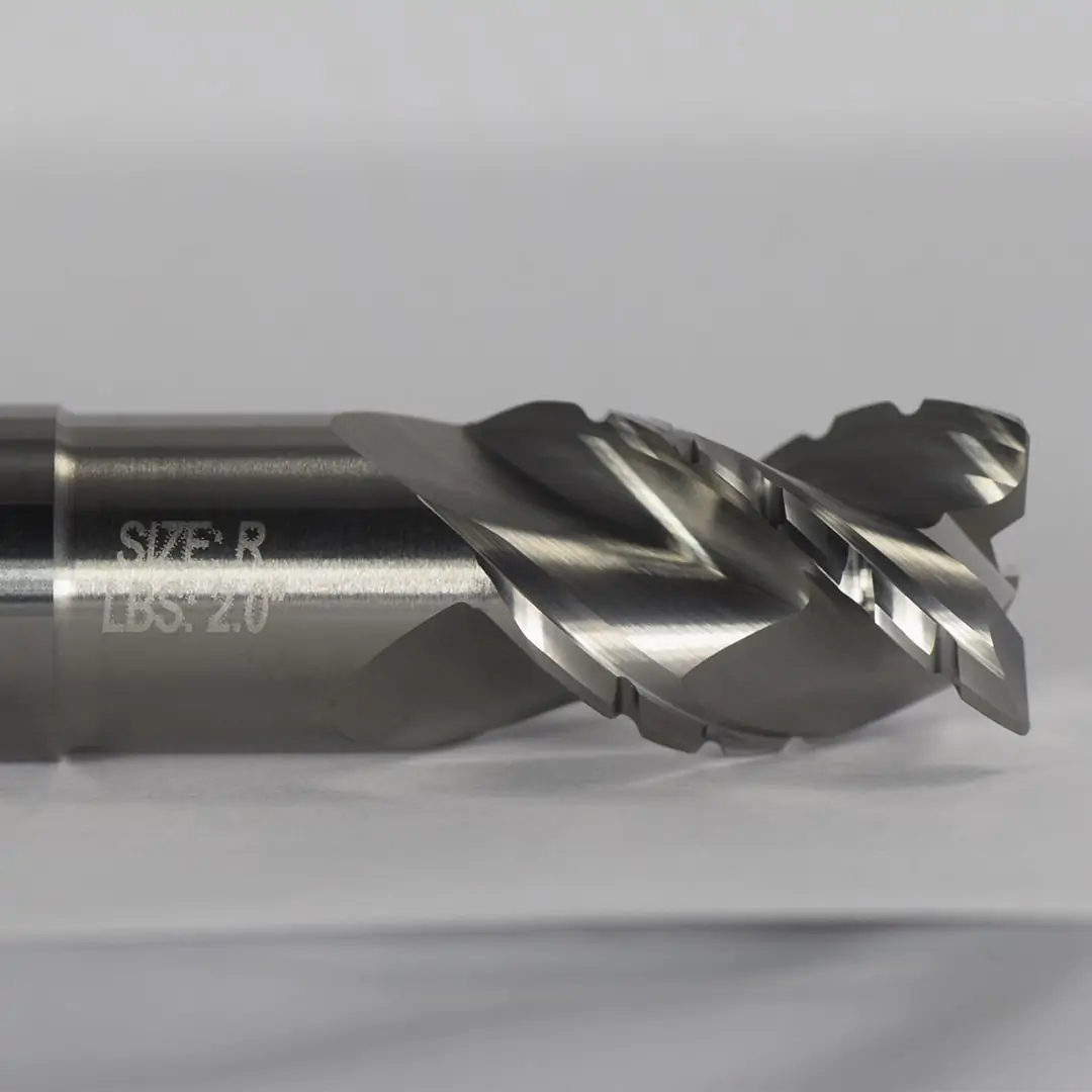
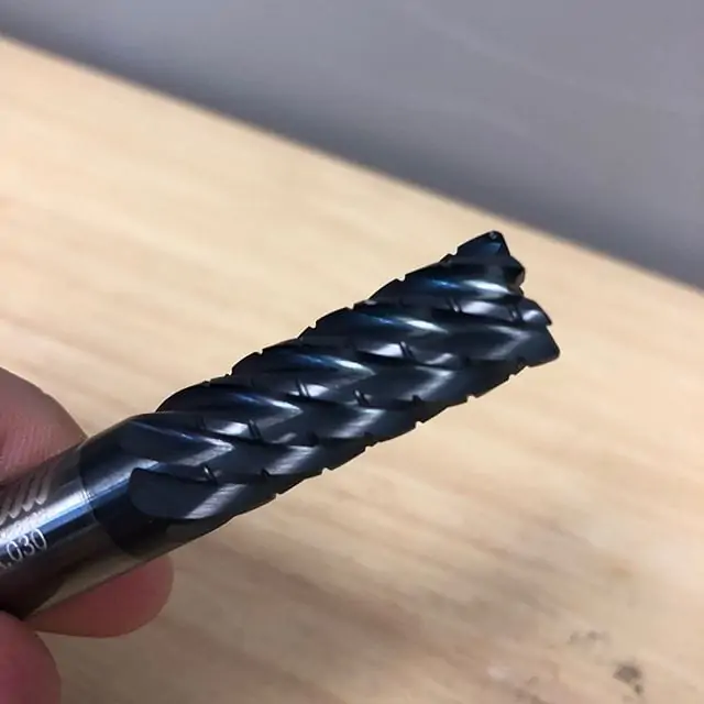
Chipbreaker End Mills feature unique notch profiles, creating a serrated cutting edge. These dividers break otherwise long, stringy chips into small, easily-managed swarf that can be cleanly evacuated from the part. But why is a chipbreaker necessary for some jobs, and not others? How does the geometry of this unique tool impact its proper running parameters? In this post, we’ll answer these questions and others to discover the very real benefits of this unique cutting geometry.

up close image of chipbreaker end mill

How Chipbreaker Tooling Works

As a tool rotates and its cutting edge impacts a workpiece, material is sheared off from a part, creating chips. When that cutting process is interrupted, as is the case with breaks in the cutting portion of the tool, chips become smaller in length and are thus easier to evacuate. Because the chipbreakers are offset flute-to-flute, a proper, flat surface finish is achieved as each flute cleans up any excess material left behind from previously passed flutes.

Benefits of Chipbreaker Tooling

Machining Efficiency

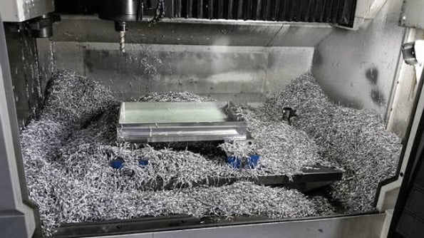
When chips are removed from the part, they begin to pile in the machine. For extensive operations, where a great deal of material is hogged out, chip accumulation can very rapidly get in the way of the spindle or part. With larger chips, accumulation occurs much faster, leaving machinists to stop their machine regularly to remove the waste. As any machinist knows, a stopped machine equates to lost money.

small metal chips in cnc machine resulting from the use of a chipbreaker end mill

Prolonged Tool Life

Inefficient chip evacuation can lead to chip recutting, or when the the tool impacts and cuts chips left behind during the machining process. This adds stresses on the tool and accelerates rate of wear on the cutting edge. Chipbreaker tooling creates small chips that are easily evacuated from a part, thus minimizing the risk of recutting.

Accelerated Running Parameters

A Harvey Performance Company Application Engineer recently observed the power of a chipbreaker tool firsthand while visiting a customer’s shop in Minnesota. The customer was roughing a great amount of 4340 Steel. Running at the parameters below, the tool was able to run uninterrupted for two hours!

Helical Part No.33737
Material4340 Steel
ADOC2.545″
RDOC.125″
Speed2,800 RPM
Feed78 IPM
Material Removal Rate24.8 Cubic In/Min


Chipbreaker Product Offering

Chipbreaker Geometry is often utilized in aluminum jobs and with other materials where long, stringy chips are common. Materials that produce a powdery chip, such as graphite, should not be machined with a chipbreaker tool, as chip evacuation would not be a concern. Helical Solutions’ line of chipbreaker tooling includes a 3-flute option for aluminum and non-ferrous materials, and its reduced neck counterpart. Additionally, Helical offers a 4-flute rougher with chipbreaker geometry for high-temp alloys and stainless steels. Harvey Tool’s expansive product offering includes a composite cutting end mill with chipbreaker geometry.

helical solutions 7 flute chipbreaker end mill cutting edges
Helical Solutions 7 Flute Chipbreaker

In Summary

Chipbreaker geometry, or grooves within the cutting face of the tool, break down chips into small, manageable pieces during the machining process. This geometry can boost shop efficiency by minimizing machine downtime to clear large chips from the machining center, improve tool life by minimizing cutting forces exerted on the tool during machining, and allow for more accelerated running parameters.

https://www.harveyperformance.com/wp-content/uploads/2017/10/Feature-Image-Chipbreaker-Tooling-IMG.jpg 600 1599 Harvey Performance Company http://www.harveyperformance.com/wp-content/uploads/2018/08/Logo_HarveyPerformanceCompany-4.png Harvey Performance Company2017-10-24 16:52:132024-03-07 16:04:28Optimize Roughing With Chipbreaker Tooling

Why Flute Count Matters

September 26, 2017/20 Comments/in CNC Machining, Helical Solutions, High Efficiency Milling, Tech Tips, Tool Geometry, Tool Selection/by Harvey Performance Company

One of the most important considerations when choosing an end mill is determining which flute count is best for the job at hand. Both material and application play an important role in this critical part of the tool selection process. Understanding the effects of flute count on other tool properties, and how a tool will behave in different situations is an essential consideration in the tool selection process. As end mills have become more and more advanced, certain standards have been created for flute counts in certain materials. While there is obvious overlap due to a myriad of factors, proper flute count is critical for machining success and ensuring you are making the most of your end mill and it’s associated MRR.

Machining Advisor Pro (MAP) Takes Flute Count Into Consideration When Helping You Dial In Running Parameters.

Click Here to Get Started.

Tool Geometry Basics

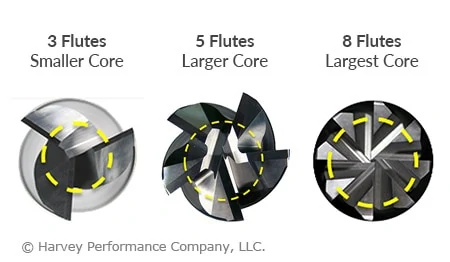
Generally, tools with more flutes have a larger core and smaller flute valleys than tools with fewer flutes.  More flutes with a larger core can provide both benefits and restrictions depending on the application.  Simply put, a larger core is directly proportional to tool strength; the larger the core, the stronger a tool will be.  In turn, a larger core also reduces the flute depth of a tool, restricting the amount of space for chips to exist.  This can cause issues with chip packing in applications requiring heavy material removal.  However, these considerations only lead us part way when making a decision on which tool to use, and when.

3, 5, and 8 flute end mills and their core sizes in relation to flute valleys

Material Considerations

Traditionally, end mills came in either a 2 flute or 4 flute option.  The widely accepted rule of thumb was to use 2 flutes for machining aluminum and non-ferrous materials, and 4 flutes for machining steel and harder alloys.  As aluminum and non-ferrous alloys are typically much softer than steels, a tool’s strength is less of a concern, a tool can be fed faster, and larger material removal rates (MRR) is facilitated by the large flute valleys of 2 flute tools.

Consequently, ferrous materials are typically much harder, and require the strength of a larger core.  Feed rates are slower, resulting in smaller chips, and allowing for the smaller flute valleys of a larger core tool.  This also allows for more flutes to fit on the tool, which in turn increases productivity.

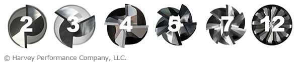
end mill flute count comparisons

Recently, with more advanced machines and toolpaths, higher flute count tools have become the norm in manufacturing.  Non-ferrous tooling has become largely centered on 3 flute tools. This has created a slight advantage over 2 flute tools by increasing productivity while still affording proper chip evacuation. The softness of non-ferrous materials affords a much deeper flute valley. As previously discussed, this allows the tool to be fed much faster than in ferrous materials. Adding an additional flute increases the productivity of the tool, while still affording machinists faster feed rates.

Ferrous tooling has taken a step further and progressed not only to 5 and 6 flutes, but up to 7 flutes and more in some cases.  With a wider range of hardness, sometimes at the very top of the Rockwell hardness scale, many more flutes have allowed longer tool life, less tool wear, stronger tools, and less deflection.  All of this results in more specialized tools for more specific materials. Material specific tooling combines proper flute counts with coatings that aid in lubricity and heat generation to ensure the most effective end mill possible in the material being machined. The end result is higher MRR and increased productivity across the entire range of ferrous materials that machinists will work with in their shops.

Running Parameters

Just as material considerations will have an impact on the tool you choose, operation type and depth of cut requirements may also have a big impact on the ideal number of flutes for your application.  In roughing applications, lower flute counts may be desirable to evacuate large amounts of chips faster with larger flute valleys.  That said, there is a balance to find, as modern toolpaths such as High Efficiency Milling (HEM) can achieve extreme MRR with a very small step over, and a higher number of flutes.  In a more traditional sense, higher flute counts are great for finishing operations where very small amounts of material are being removed, and greater finish can be achieved with more flutes, not worrying as much about chip evacuation as that phase has already been accomplished during roughing.

helical end mill with lines showcasing the flute valleys

Flute count plays a big role in speeds and feeds calculation as well.  One common rule of thumb is “more flutes, more feed,” but this can be a very detrimental misconception.  Although true in some cases, this is not an infinitely scalable principle.  As stated previously, increasing the number of flutes on a tool limits the size that the flute valleys can be.  While adding a 5th flute to a 4 flute tool theoretically gives you 25% more material removal per revolution with an appropriately increased feed rate, feeding the tool that much faster may overload the tool.  The 25% increase in material removal is more likely closer to 10-15%, given the tool is exactly the same in all other specifications.  Higher flute count tools may require speeds and feeds to be backed off so much in some cases, that a lower flute count may be even more efficient.  Finding the right balance is key in modern milling practices. Consulting a tooling manufacturer’s speeds and feeds will be the perfect starting point, and then machinists can make changes as they see fit to properly accomplish the job at hand.

In all, the importance of flute count identification is critical to continued success at the spindle. Different materials have different strength requirements as well as variability in how much material can be appropriately removed per tooth.

https://www.harveyperformance.com/wp-content/uploads/2017/09/Feature-Image-Why-Flute-Count-Matters-IMG.jpg 525 1400 Harvey Performance Company http://www.harveyperformance.com/wp-content/uploads/2018/08/Logo_HarveyPerformanceCompany-4.png Harvey Performance Company2017-09-26 15:00:092023-12-01 14:20:29Why Flute Count Matters

Tackling Titanium: Machining Tips and Techniques Guide

August 8, 2017/6 Comments/in CNC Machining, Gummy Materials, Helical Solutions, Machining Techniques, Material Specific, Milling, Tech Tips/by Tom Pyle

In today’s manufacturing industry, titanium and its alloys have become staples in aerospace, medical, automotive, and firearm applications. This popular metal is resistant to rust and chemicals, is recyclable, and is extremely strong for its weight. However, there are several challenges that must be considered when machining titanium and selecting the appropriate tools and parameters for the job.

Titanium Varieties

Titanium is available in many varieties, including nearly 40 ASTM grades, as well as several additional alloys. Grades 1 through 4 are considered commercially pure titanium with varying requirements on ultimate tensile strength. Grade 5 (Ti6Al4V or Ti 6-4) is the most common combination, alloyed with 6 percent aluminum and 4 percent vanadium. Although titanium and its alloys are often grouped together, there are some key differences between them that must be noted before determining the ideal machining approach.

Titanium 6AL4V chips with helical hvti end mill

Helical Solutions’ HVTI End Mill is a great choice for high efficiency toolpaths in Titanium.

Titanium Concerns

Workholding

Although titanium may have more desirable material properties than your average steel, it also behaves more flexibly, and is often not as rigid as other metals. This requires a secure grip on titanium workpieces, and as rigid a machine setup as is possible. Other considerations include avoiding interrupted cuts, and keeping the tool in motion at all times of contact with the workpiece. Dwelling in a drilled hole or stopping a tool next to a profiled wall will cause the tool to rub – creating excess heat, work-hardening the material, and causing premature tool wear.

Heat Generation

Heat is a formidable enemy, and heat generation must be considered when selecting speeds and feeds. While commercially pure grades of titanium are softer and gummier than most of its alloys, the addition of alloying elements typically raises the hardness of titanium. This increases concerns regarding generated heat and tool wear. Maintaining a larger chipload and avoiding unnecessary rubbing aids with tool performance in the harder titanium alloys, and will minimize the amount of work hardening produced. Choosing a lower RPM, paired with a larger chipload, can provide a significant reduction in temperature when compared to higher speed options. Due to its low conduction properties, keeping temperatures to a minimum will put less stress on the tool and reduce wear. Using high-pressure coolant is also an effective method to reduce heat generation when machining titanium.

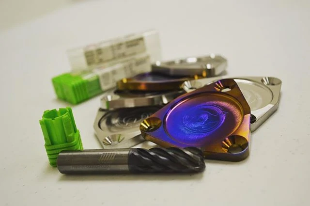
mitsubishi evo camshaft cutters machine from titanium with helical solutions end mill

These camshaft covers were custom made in titanium for Mitsubishi Evos.
Photo courtesy of @RebootEng (Instagram)

Galling and Built-Up Edge

The next hurdle to consider is that titanium has a strong tendency to adhere to a cutting tool, creating built up edge. This is a tricky issue which can be reduced by using copious amounts of high pressure coolant aimed directly at the cutting surface. The goal is to remove chips as soon as possible to prevent chip re-cutting, and keep the flutes clean and clear of debris. Galling is a big concern in the commercially pure grades of titanium due to their “gummy” nature. This can be addressed using the strategies mentioned previously, such as continuing feed at all times of workpiece contact, and using plenty of high-pressure coolant.

Titanium Solutions

While the primary concerns when machining titanium and its alloys may shift, the methods for mitigating them remain somewhat constant. The main ideas are to avoid galling, heat generation, work hardening, and workpiece or tool deflection. Use a lot of coolant at high pressure, keep speeds down and feeds up, keep the tool in motion when in contact with the workpiece, and use as rigid of a setup as possible.

In addition, selecting a proper tool coating can help make your job a successful one. With the high heat being generated during titanium machining operations, having a coating that can adequately deal with the temperature is key to maintaining performance through an operation. The proper coating will also help to avoid galling and evacuate chips effectively. Coatings such as Harvey Tool’s Aluminum Titanium Nitride (AlTiN Nano) produce an oxide layer at high temperatures, and will increase lubricity of the tool.

Tooling Solutions

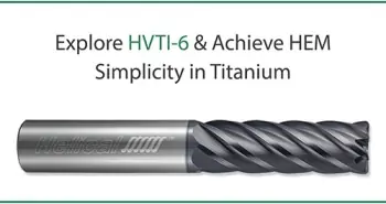
Helical Solutions offers the HVTI-6 line of tooling optimized for High Efficiency Milling (HEM) in Titanium and its alloys. Helical’s HVTI-6 features its Aplus coating which offers added lubricity and high temperature resistance for improved tool life and faster speeds and feeds.

As titanium and its many alloys continue to grow in use across various industries, more machinists will be tasked with cutting this difficult material. However, heat management and appropriate chip evacuation, when paired with the correct coating, will enable a successful run and profitable tool life.

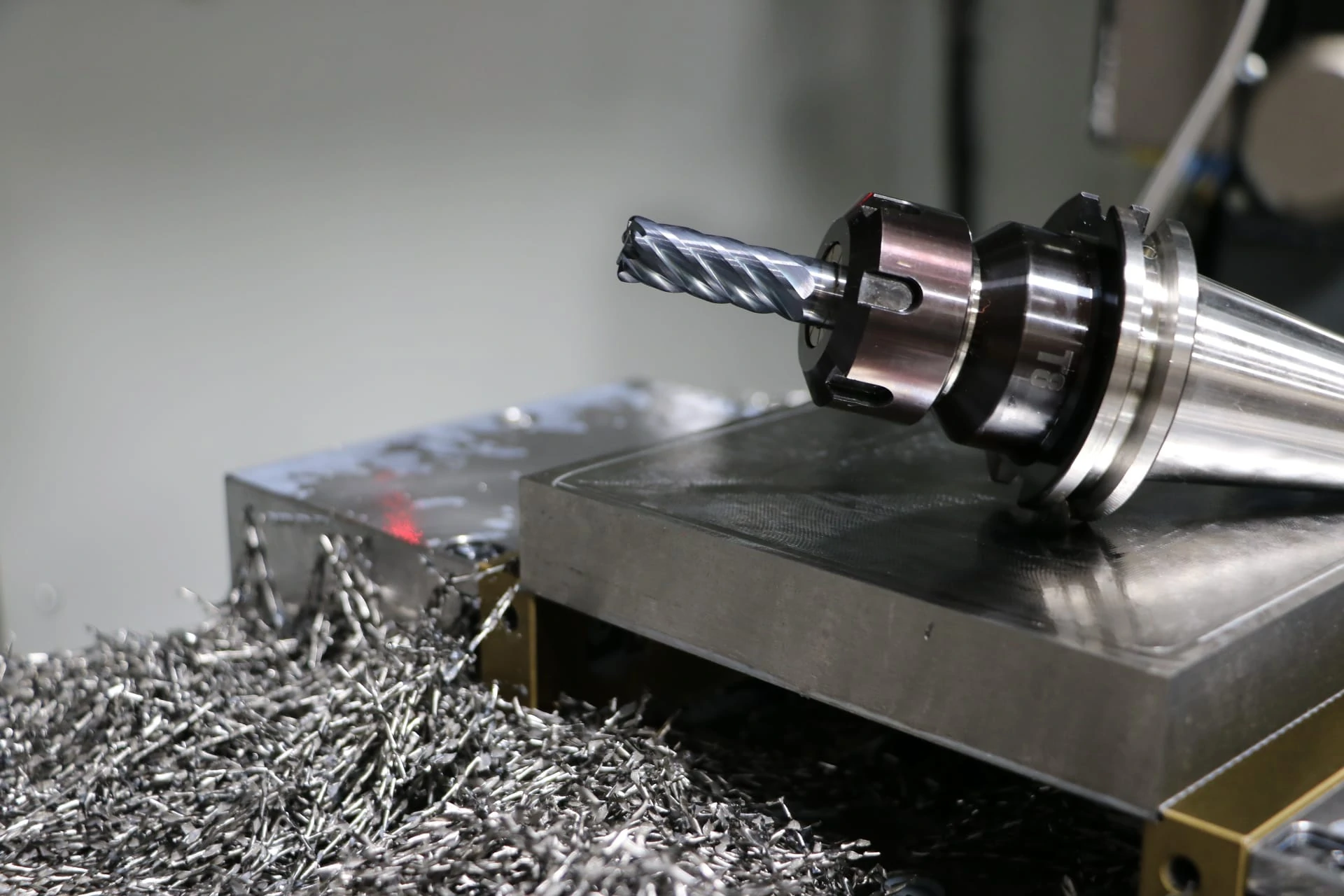
machining titanium

https://www.harveyperformance.com/wp-content/uploads/2017/08/Featured-Image-Tackling-Titanium-IMG.jpg 525 1400 Tom Pyle http://www.harveyperformance.com/wp-content/uploads/2018/08/Logo_HarveyPerformanceCompany-4.png Tom Pyle2017-08-08 16:00:512025-11-12 15:53:48Tackling Titanium: Machining Tips and Techniques Guide
Page 3 of 3123
BLOG HOME

Search In the Loupe

More results...

Browse by Topic

How-To’s
Technical Tips
Tools In Action
Featured Customers
Tool Guides

Free Drilling Guidebook

DOWNLOAD

Recent Posts

  • Machining a Complex Part with Harvey Tool
  • Drill Substrate Guide: HSS vs Cobalt vs Carbide
  • The Key Differences Between Helical’s Tool Coatings

Stay In The Loupe!

Sign up to receive a monthly recap of:
– The latest machining solutions
– Machining tips and tricks
– A recap of our most popular posts

SIGN UP

Contact Us


Address
428 Newburyport Turnpike
Rowley, MA 01969

Website
www.harveyperformance.com

Phone
Harvey Tool Tech: 1.800.645.5609
Helical Solutions Tech: 1.866.543.5422
Micro 100 Tech: 1.800.421.8065
Titan USA Tech: 1.888.482.6872

Email
[email protected]
[email protected]
[email protected]
[email protected]
[email protected]

CONTACT US

428 Newburyport Turnpike
Rowley, MA 01969-1729

844-393-8665

[email protected]

HARVEY PERFORMANCE

Company Overview
Our Unique Strengths
Industries Served
Careers
Sustainability
Privacy Policy

OUR BRANDS

Harvey Tool
Helical Solutions
Micro 100
Titan USA
CoreHog
Valor Holemaking

OUR BRANDS

ATA Air Tools
ATA SGSPRO
Garryson
Industrial Tooling Corporation (ITC)
Karnasch
Van Hoorn Carbide

Copyright © 2022 Harvey Performance Company, LLC
  • Link to LinkedIn
  • Link to Facebook
Scroll to top Scroll to top Scroll to top