Harvey Performance Company
  • About Us
    • Company Overview
    • Our Unique Strengths
    • Our Partners
    • Our History
    • Our Locations
    • Sustainability
    • Giving Back
      • Giving Back
      • One Tree Planted
    • News
      • News
      • Press
  • Our Brands
    • Harvey Tool
    • Helical Solutions
    • Micro 100
    • Titan USA
    • CoreHog
    • Valor Holemaking
    • ATA Air Tools
    • ATA SGSPRO
    • Garryson
    • Industrial Tooling Corporation (ITC)
    • Karnasch
    • Van Hoorn Carbide
  • Products
    • Milling
    • Drilling
    • Grinding
    • Micro Tools
    • Sinking
    • Sawing
    • Composite Tools
    • Threading
    • Turning
    • Beveling
    • Reaming
    • Air Tools
  • Solutions
    • Aerospace
    • Automotive
    • Defense
    • Energy
    • Foundries
    • Marine
    • Medical
    • Mold & Die
    • Oil & Gas
    • Power Generation
    • Rail
  • Resources
    • CAM & TDM Tool Libraries
    • Machining Advisor Pro
    • In the Loupe Blog
    • Webinars
  • Careers
  • Contact Us
  • Menu Menu
  • Link to LinkedIn
  • Link to Facebook

How to Avoid Common Part Finish Problems

April 25, 2017/7 Comments/in CNC Machining, How-To's, Machining 101, Quick Tips, Troubleshooting Tips/by Harvey Performance Company

Part Finish Reference Guide

Finishing cuts are used to complete a part, achieving its final dimensions within tolerance and its required surface finish. Most often an aesthetic demand and frequently a print specification, surface finish can lead to a scrapped part if requirements are not met. Meeting finish requirements in-machine has become a major point of improvement in manufacturing, as avoiding hand-finishing can significantly reduce costs and cycle times.

Common Finishing Problems

  • Burrs
  • Scallop marks
  • Chatter Marks

Factors That Influence Part Finish

  • Specific material and hardness
  • Cutting tool speeds & feeds
  • Tool design and deployment
  • Tool projection and deflection
  • Tool-to-workpiece orientation
  • Rigidity of workholding
  • Coolant and lubricity
  • Final-pass depth of cut

Finishing Problem Solutions

  • Tools with high helix angles and flute counts work best for finishing operations. Softer materials show great results with higher helices, while harder materials can benefit greatly from increased flute counts.
  • Increase your RPM and lower your IPT (Figure 2).
  • Ensure that tool runout is extremely minimal.
  • Use precision tool holders that are in good condition, are undamaged, and run true.
  • Opt for a climb milling machining method.
  • Use tooling with Variable Pitch geometry to help reduce chatter.
  • A proper radial depth of cut (RDOC) should be used. For finishing operations, the RDOC should be between 2 and 5 percent of the tool’s Cutter Diameter.
  • For long reach walls, use reduced neck tooling which help to minimize deflection (Figure 3).
  • Extreme contact finishing (3x cutter diameter), may require a 50% feed rate reduction.

part finish guide

length of cut

Common Surface Finish Nomenclature

Ra = Roughness average
Rq = RMS (Root Mean Square) = Ra x 1.1
Rz = Ra x 3.1

part finish guide

Share this entry
  • Share on Facebook
  • Share on X
  • Share on WhatsApp
  • Share on Pinterest
  • Share on LinkedIn
  • Share on Reddit
  • Share by Mail

https://www.harveyperformance.com/wp-content/uploads/2017/04/Feature-Image-Part-Finish-Reference-Guide-IMG.jpg 525 1400 Harvey Performance Company http://www.harveyperformance.com/wp-content/uploads/2018/08/Logo_HarveyPerformanceCompany-4.png Harvey Performance Company2017-04-25 12:30:242022-06-08 09:21:37How to Avoid Common Part Finish Problems

How to Combat Chip Thinning

March 13, 2017/2 Comments/in CNC Machining, CNC Programming, High Efficiency Milling, How-To's, Machining Techniques, Quick Tips/by Tom Pyle

The following is just one of several blog posts relevant to High Efficiency Milling. To achieve a full understanding of this popular machining method, view any of the additional HEM posts below!

Introduction to High Efficiency Milling I High Speed Machining vs. HEM I Diving into Depth of Cut I How to Avoid 4 Major Types of Tool Wear I Intro to Trochoidal Milling


Defining Chip Thinning

Chip Thinning is a phenomenon that occurs with varying Radial Depths Of Cut (RDOC), and relates to chip thickness and feed per tooth. While these two values are often mistaken as the same, they are separate variables that have a direct impact on each other.

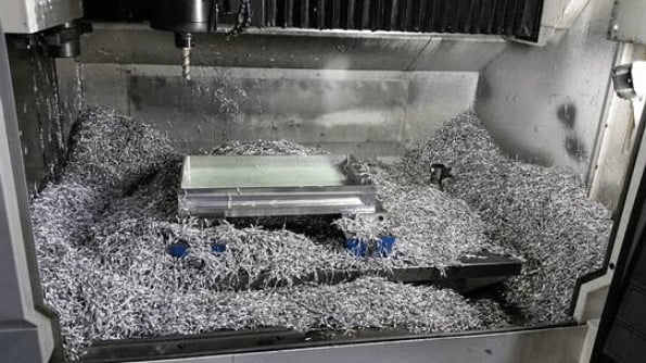
cnc machining setup covered in chips

Radial Depth of Cut

Radial Depth of Cut denotes the distance that a tool advances into a workpiece, also known as Stepover, Cut Width, or XY.

Feed Per Tooth

Feed per tooth translates directly to your tool feed rate, and is commonly referred to as Inches Per Tooth (IPT) or chip load.

Chip Thickness

Chip thickness is often overlooked. It refers to the actual thickness of each chip cut by a tool, measured at its largest cross-section. Users should be careful not to confuse chip thickness and feed per tooth, as these are each directly related to the ideal cutting conditions.

Download the Free, 50+ Page High Efficiency Milling Guidebook Today

How Chip Thinning Occurs

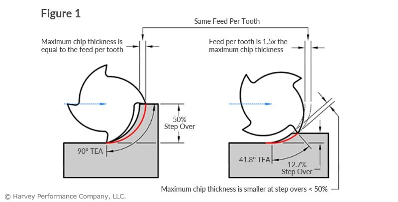
When using a 50% step over (left side of Figure 1), the chip thickness and feed per tooth are equal to each other. Each tooth will engage the workpiece at a right angle, allowing for the most effective cutting action, and avoiding rubbing as much as possible. Once the RDOC falls below 50% of the cutter diameter (right side of Figure 1), the maximum chip thickness decreases, in turn changing the ideal cutting conditions of the application. This can lead to poor part finish, inefficient cycle times, and premature tool wear. Properly adjusting the running parameters can greatly help reduce these issues.

comparison of radial chip thinning and feed per tooth

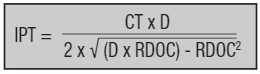
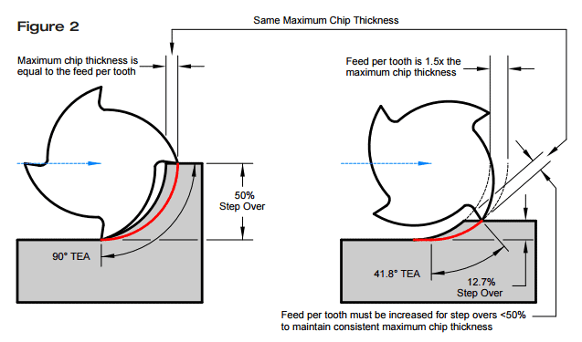
The aim is to achieve a constant chip thickness by adjusting the feed rate when cutting at different RDOC. This can be done with the following equation using the Tool Diameter (D), RDOC, Chip Thickness (CT), and Feed Rate (IPT). For chip thickness, use the recommended value of IPT at 50% step over. Finding an adjusted feed rate is as simple as plugging in the desired values and solving for IPT. This keeps the chip thickness constant at different depths of cut. The adjustment is illustrated in Figure 2.

Inches Per Tooth (Chip Thinning Adjustment)

IPT chip thinning formula
radial chip thinning adjustment profiles

Lasting Benefits

In summary, the purpose of these chip thinning adjustments is to get the most out of your tool. Keeping the chip thickness constant ensures that a tool is doing as much work as it can within any given cut. Other benefits include: reduced rubbing, increased material removal rates, and improved tool life.

High efficiency milling guidebook download
https://www.harveyperformance.com/wp-content/uploads/2017/03/Feature-Image-Chip-Thinning-IMG-1.jpg 525 1400 Tom Pyle http://www.harveyperformance.com/wp-content/uploads/2018/08/Logo_HarveyPerformanceCompany-4.png Tom Pyle2017-03-13 18:49:392024-02-27 10:32:43How to Combat Chip Thinning
Page 3 of 3123
BLOG HOME

Search In the Loupe

More results...

Browse by Topic

How-To’s
Technical Tips
Tools In Action
Featured Customers
Tool Guides

Free Drilling Guidebook

DOWNLOAD

Recent Posts

  • Machining a Complex Part with Harvey Tool
  • Drill Substrate Guide: HSS vs Cobalt vs Carbide
  • The Key Differences Between Helical’s Tool Coatings

Stay In The Loupe!

Sign up to receive a monthly recap of:
– The latest machining solutions
– Machining tips and tricks
– A recap of our most popular posts

SIGN UP

Contact Us


Address
428 Newburyport Turnpike
Rowley, MA 01969

Website
www.harveyperformance.com

Phone
Harvey Tool Tech: 1.800.645.5609
Helical Solutions Tech: 1.866.543.5422
Micro 100 Tech: 1.800.421.8065
Titan USA Tech: 1.888.482.6872

Email
[email protected]
[email protected]
[email protected]
[email protected]
[email protected]
Scroll to top Scroll to top Scroll to top