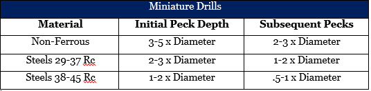
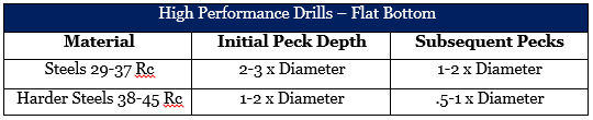
Utilizing a proper pecking cycle strategy when drilling is important to both the life of your tool and its performance in your part. Recommended cycles vary depending on the drill being used, the material you’re machining, and your desired final product.
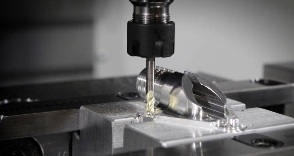
Rather than drill to full drill depth in one single plunge, pecking cycles involve several passes – a little at a time. Peck drilling aids the chip evacuation process, helps support tool accuracy while minimizing walking, prevents chip packing and breakage, and results in a better all around final part.
Note: For hole depths 12x or greater, a pilot hole of up to 1.5X Diameter is recommended.
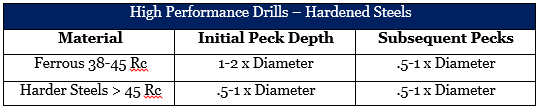
High Performance Drills – Hardened Steels
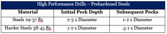
High Performance Drills – Prehardened Steels
Key Pecking Cycle Takeaways
From the above tables, it’s easy to identify how recommended peck drilling cycles change based on the properties of the material being machined. Unsurprisingly, the harder the material is, the shorter the recommended pecking depths are. As always, miniature drills with a diameter of less than .010″ are extremely fragile and require special precautions to avoid immediate failure. For help with your specific job, contact the Harvey Tool Technical Team at 800-645-5609 or [email protected]
https://www.harveyperformance.com/wp-content/uploads/2018/04/Featured-Image-Pecking-Cycle-IMG-1.jpg5251400Harvey Performance Companyhttp://www.harveyperformance.com/wp-content/uploads/2018/08/Logo_HarveyPerformanceCompany-4.pngHarvey Performance Company2018-04-19 07:44:542022-01-17 10:16:34Choosing the Right Pecking Cycle Approach
Coolant in purpose is widely understood – it’s used to temper high temperatures common during machining, and aid in chip evacuation. However, there are several types and styles, each with its own benefits and drawbacks. Knowing which cnc coolant – or if any – is appropriate for your job can help to boost your shop’s profitability, capability, and overall machining performance.
Coolant or Lubricant Purpose
Coolant and lubricant are terms used interchangeably, though not all coolants are lubricants. Compressed air, for example, has no lubricating purpose but works only as a cooling option. Direct coolants – those which make physical contact with a part – can be compressed air, water, oil, synthetics, or semi-synthetics. When directed to the cutting action of a tool, these can help to fend off high temperatures that could lead to melting, warping, discoloration, or tool failure. Additionally, coolant can help evacuate chips from a part, preventing chip recutting and aiding in part finish.
Coolant can be expensive, however, and wasteful if not necessary. Understanding the amount of coolant needed for your job can help your shop’s efficiency.
CNC coolant is delivered in several different forms – both in properties and pressure. The most common forms include air, mist, flood coolant, high pressure, and Minimum Quantity Lubricant (MQL). Choosing the wrong pressure can lead to part or tool damage, whereas choosing the wrong amount can lead to exhausted shop resources.
Air: Cools and clears chips, but has no lubricity purpose. Air coolant does not cool as efficiently as water or oil-based coolants. For more sensitive materials, air coolant is often preferred over types that come in direct contact with the part. This is true with many plastics, where thermal shock – or rapid expansion and contraction of a part – can occur if direct coolant is applied.
Mist: This type of low pressure coolant is sufficient for instances where chip evacuation and heat are not major concerns. Because the pressure applied is not great in a mist, the part and tool do not undergo additional stresses.
Flood: This low pressure method creates lubricity and flushes chips from a part to avoid chip recutting, a common and tool damaging occurrence.
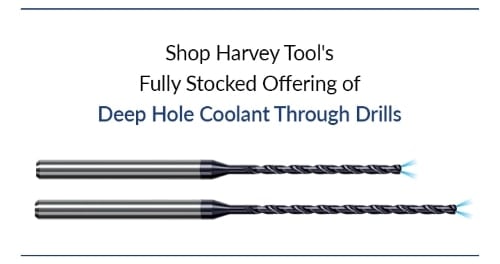
High Pressure: Similar to flood coolant, but delivered in greater than 1,000 psi. This is a great option for chip removal and evacuation, as it blasts the chips away from the part. While this method will effectively cool a part immediately, the pressure can be high enough to break miniature diameter tooling. This method is used often in deep pocket or drilling operations, and can be delivered via coolant through tooling, or coolant grooves built into the tool itself. Harvey Tool offers Coolant Through Drills, while Titan USA proudly offers Coolant-Fed ThreadMills
Minimum Quantity Lubricant (MQL): Every machine shop focuses on how to gain a competitive advantage – to spend less, make more, and boost shop efficiency. That’s why many shops are opting for MQL, along with its obvious environmental benefits. Using only the necessary amount of coolant will dramatically reduce costs and wasted material. This type of lubricant is applied as an aerosol, or an extremely fine mist, to provide just enough coolant to perform a given operation effectively.
To see all of these coolant styles in action, check out the video below from our partners at CimQuest.
In Conclusion
CNC coolant is all-too-often overlooked as a major component of a machining operation. The type of coolant or lubricant, and the pressure at which it’s applied, is vital to both machining success and optimum shop efficiency. Coolant can be applied as compressed air, mist, in a flooding property, or as high pressure. Certain machines also are MQL able, meaning they can effectively restrict the amount of coolant being applied to the very amount necessary to avoid being wasteful.
https://www.harveyperformance.com/wp-content/uploads/2017/12/Feature-Image-Coolant-for-CNC-Machining-IMG.jpg5251400Harvey Performance Companyhttp://www.harveyperformance.com/wp-content/uploads/2018/08/Logo_HarveyPerformanceCompany-4.pngHarvey Performance Company2017-12-05 15:09:342022-04-20 16:52:22What You Need to Know About Coolant for CNC Machining
Cutting tools undergo a great deal of force during the machining process, which cause vibrations – also known as chatter or harmonics. Avoiding these vibrations entirely is not possible, though minimizing them is pivotal for machining success. Vibrations become damaging when proper machining steps are not followed. This leads to strong, part-ruining chatter. In these situations, parts have what is known as “chatter marks,” or clear vibration marks along the surface of a part. Tools can experience an increased rate of wear due to excess vibration.
It seems elementary, but selecting the best tool for your application can be confusing. With so many different geometric styles for tooling – overall length, length of cut, reach, number of flutes – it can sometimes be difficult to narrow down one specific tool for your job. Oftentimes, machinists opt for general purpose tooling that can perform a variety of operations, overlooking the option that’s optimized for one material and job.
Use Material Specific Tooling
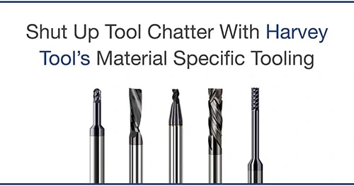
Opting for Material Specific Tooling is helpful, as each material has different needs. For example, steels are machined differently than aluminum materials. Everything from the chip size, to chip evacuation, is different. Variable Helix or Variable Pitch designs help to minimize chatter by reducing harmonics, which are caused by the cutting edge having repeated contact with the workpiece. In order to reduce harmonics, the time intervals between flute contact with the workpiece are varied.
Consider Tool Length
Overall length is another important factor to consider when deciding on a tool for your job. The more overhang, or length the tool hangs from the spindle, the less secure the spindle-to-tool connection is, and the more vibration. Ensuring that your tool is only as long as needed for your operation is important to minimizing chatter and harmonics. If machining deep within a part, opt for reached tooling or an extended reach tool holder to help solidify the connection.
Ensure a Secure Connection
Tool Holder & Shank Relationship
When it comes to secure tool holding approaches, both the tool shank and the collet are important. A loose tool, unsurprisingly, has more ability to move, or vibrate, during machining. With this in mind, Helical offers Shank Configurations to help the connection including the ToughGRIP Shank, which replaces a smooth, mirror-like surface with a rougher, coarser one for increased friction. Helical is also a licensee of the HAIMER Safe-Lock™, added grooves on the shank of a tool that work opposite of the spindle rotation, securely fastening the tool in place.
Choosing Collet Types
Machinists must also know the different types of collets available to them to identify if a better solution might be necessary. For example, Hydraulic Tool Holders or Shrink Fit Tool Holders promote a stronger connection than a Mechanical Spindle Tightening method.
How a tool is run can mean the difference between stellar job results and a ruined part. This includes both the parameters a tool is run at, as well as the direction by which it rotates – either a Conventional Milling or a Climb Milling technique. The key distinction between these two methods lies in the relationship between the cutter’s rotation and the direction of the feed.
Conventional Milling
In conventional milling, the chip width starts from zero and increases gradually, causing the process of heat generation onto the workpiece rather than the chips. Heat generation causes deformities and tool failure such as work hardening, creating more headaches for a machinist. For this reason, conventional milling is generally only recommended for tools with high toughness or for breaking into case hardened materials.
Climb Milling
Most modern machine shops will use a climb milling technique, or when the chip width starts at its maximum and decreases during the cut. Climb Milling will offer a more consistent cut than traditional methods, and puts less stress on the tool. Think of it like weight lifting – doing the heavy lifting will be easiest at the beginning of your workout. Similarly, a cut in which the thickest chip is removed first helps the tool maintain its strength. Because the chip cutting process is more swift, vibrations are minimized.
Vibrations are unavoidable during the machining process, but minimizing them can mean the difference between successful machining and scrapped parts. Following three simple rules can help to keep your chatter and harmonics under control, including: Selecting the right tool, ensuring a secure machine-tool connection, and using it in a climb milling strategy. Both Harvey Tool and Helical Solutions have tools that can help, including shank modifications and Variable Helix or Variable Pitch end mills.
https://www.harveyperformance.com/wp-content/uploads/2017/11/Feature-Image-Tool-Chatter-IMG.jpg5251400Harvey Performance Companyhttp://www.harveyperformance.com/wp-content/uploads/2018/08/Logo_HarveyPerformanceCompany-4.pngHarvey Performance Company2017-11-08 09:30:472023-12-01 16:08:473 Steps to Shutting up Tool Chatter
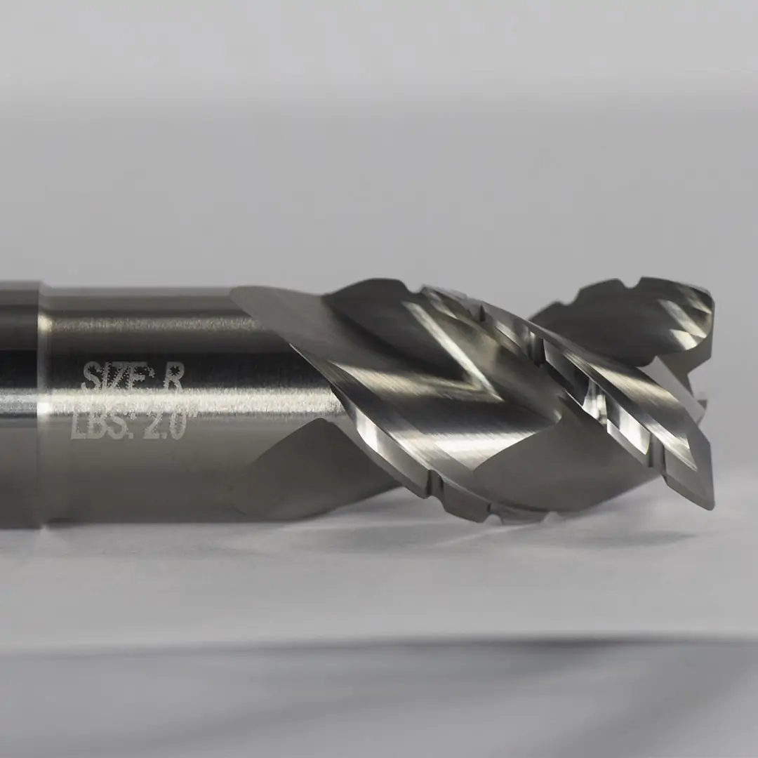
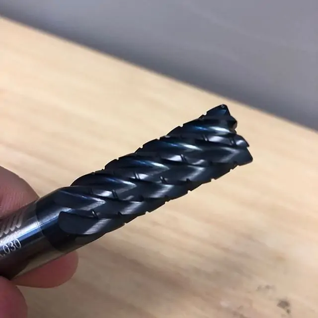
Chipbreaker End Mills feature unique notch profiles, creating a serrated cutting edge. These dividers break otherwise long, stringy chips into small, easily-managed swarf that can be cleanly evacuated from the part. But why is a chipbreaker necessary for some jobs, and not others? How does the geometry of this unique tool impact its proper running parameters? In this post, we’ll answer these questions and others to discover the very real benefits of this unique cutting geometry.
How Chipbreaker Tooling Works
As a tool rotates and its cutting edge impacts a workpiece, material is sheared off from a part, creating chips. When that cutting process is interrupted, as is the case with breaks in the cutting portion of the tool, chips become smaller in length and are thus easier to evacuate. Because the chipbreakers are offset flute-to-flute, a proper, flat surface finish is achieved as each flute cleans up any excess material left behind from previously passed flutes.
Benefits of Chipbreaker Tooling
Machining Efficiency
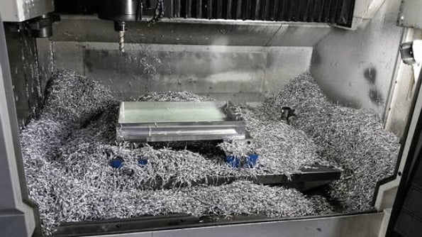
When chips are removed from the part, they begin to pile in the machine. For extensive operations, where a great deal of material is hogged out, chip accumulation can very rapidly get in the way of the spindle or part. With larger chips, accumulation occurs much faster, leaving machinists to stop their machine regularly to remove the waste. As any machinist knows, a stopped machine equates to lost money.
Prolonged Tool Life
Inefficient chip evacuation can lead to chip recutting, or when the the tool impacts and cuts chips left behind during the machining process. This adds stresses on the tool and accelerates rate of wear on the cutting edge. Chipbreaker tooling creates small chips that are easily evacuated from a part, thus minimizing the risk of recutting.
Accelerated Running Parameters
A Harvey Performance Company Application Engineer recently observed the power of a chipbreaker tool firsthand while visiting a customer’s shop in Minnesota. The customer was roughing a great amount of 4340 Steel. Running at the parameters below, the tool was able to run uninterrupted for two hours!
Chipbreaker geometry, or grooves within the cutting face of the tool, break down chips into small, manageable pieces during the machining process. This geometry can boost shop efficiency by minimizing machine downtime to clear large chips from the machining center, improve tool life by minimizing cutting forces exerted on the tool during machining, and allow for more accelerated running parameters.
NOTE: This article covers speeds and feed rates for milling tools, as opposed to turning tools.
Before using a cutting tool, it is necessary to understand tool cutting speeds and feed rates, more often referred to as “speeds and feeds.” Speeds and feeds are the cutting variables used in every milling operation and vary for each tool based on cutter diameter, operation, material, etc.
Understanding the right speeds and feeds for your tool and operation before you start machining is critical. These are to be used to set baselines for a particular tool, ensuring proper performance without compromising part finish and tool life.
NOTE: This article covers speeds and feed rates for milling tools, as opposed to turning tools.
Understanding SFM Calculations
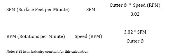
It is first necessary to define each of these factors. Cutting speed, also referred to as surface speed, is the difference in speed between the tool and the workpiece, expressed in units of distance over time known as SFM (surface feet per minute).
For set-ups with stationary workpieces, SFM is the speed at which a tool moves across the part in the cut. The speed difference must be calculated in set ups where the part and tool are both moving in multi-axis machining set-ups.
Surface Foot is based on the various properties of the given material. Speed, referred to as Rotations Per Minute (RPM) is based off of the SFM and the cutting tool’s diameter. As SFM is tied to the properties of a material, it does not change based upon the operation being performed and remains constant despite changes in chip load calculation.
How Do You Calculate Surface Feet per Minute (SFM)?
The SFM calculation utilizes the industry standard of 3.82. Here, the cutter diameter of the chosen tool is multiplied by the speed or RPM. This figure is then divided by 3.82 to generate the SFM or Surface Feet per Minute.
Feed Rate and Chip Load Calculations
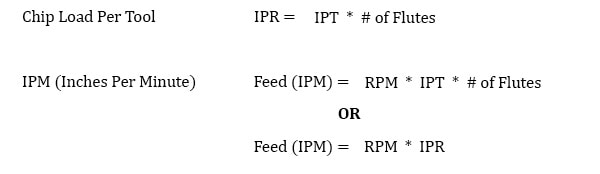
While speeds and feeds are common terms used in the programming of the cutter, the ideal running parameters are also influenced by a myriad of other variables. As speeds and feeds must be well-matched to be effective, the speed of the cutter is used in the calculation of the cutter’s feed rate, measured in Inches Per Minute (IPM).
The other part of the equation is the chip load, or material being removed per revolution. It is important to note that chip load per tooth and chip load per tool are different:
Chip load per tooth is the appropriate amount of material that one cutting edge of the tool should remove in a single revolution. This is measured in Inches Per Tooth (IPT).
Chip load per tool is the appropriate amount of material removed by all cutting edges on a tool in a single revolution. This is measured in Inches Per Revolution (IPR).
A chip load that is too large can pack up chips in the cutter, causing poor chip evacuation and eventual breakage. A chip load that is too small can cause rubbing, chatter, tool deflection, and a poor overall cutting action. Finding the correct balance will not only allow for the most efficient cut possible, but also ensures the most efficiency in regard to tool wear. When calculating chip load per tool or IPR, the per tooth chip load is aptly multiplied by the number of flutes on the tool itself.
Material Removal Rate
Material Removal Rate (MRR), while not part of the cutting tool’s program, is a helpful way to calculate a tool’s efficiency. MRR takes into account two very important running parameters: Axial Depth of Cut (ADOC), or the distance a tool engages a workpiece along its centerline, and Radial Depth of Cut (RDOC), or the distance a tool is stepping over into a workpiece.
The MRR calculation (seen below) relies on the calculated feed rate. The feed rate (IPM) is multiplied by the radial and axial depths of cut to produce the rate of removal.
The tool’s depth of cuts and the rate at which it is cutting can be used to calculate how many cubic inches per minute (in3/min) are being removed from a workpiece. This equation is extremely useful for comparing cutting tools and examining how cycle times can be improved. Decreased cycle times leads to higher productivity within a shop, which is what all machinists aim for during production.
Adjusting depths of cut can decrease time in cut and overall production time, freeing up machines for additional manufacturing. An example of depth of cut adjustment is seen in High Efficiency Milling, where RDOC is decreased and ADOC is increased. In this method, MRR is increased while also reducing tool wear, leading to higher productivity and more parts per tool.
Speeds and Feeds In Practice
While many of the cutting parameters are set by the tool and workpiece material, the depths of cut taken also affect the feed rate of the tool. The depths of cuts are dictated by the operation being performed – this is often broken down into slotting, roughing, and finishing. Though there are many other more specific types of operations.
These unique operations utilize much different depths of cut, with industry standardized terms as description. Slotting can be described as utilizing 180° of the diameter of the tool engaged in the cut.
Roughing on the other hand will typically disperse both ADOC and RDOC relatively evenly. Finally, finishing operations will use substantially more axial depths of cut in relation to radial, leaving the best finish possible on the workpiece.
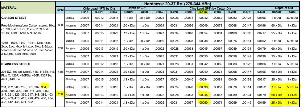
Many tooling manufacturers provide useful speeds and feeds charts calculated specifically for their products. For example, Harvey Tool provides the following chart for a 1/8” diameter end mill, tool #50308.
A customer can find the SFM for the material on the left, in this case 304 stainless steel (highlighted in yellow). The chip load (per tooth) can be found by intersecting the tool diameter on the top (blue heading) with the material and operations (based on axial and radial depth of cut), highlighted in the image below.
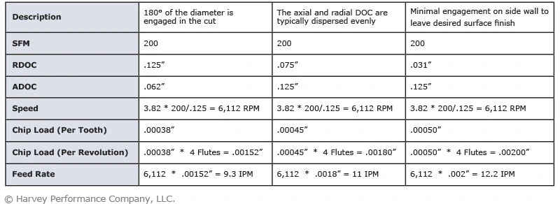
The following table calculates the speeds and feeds for this tool (#50308) and material (304 Stainless) for each operation, based on the chart above:
Each operation recommends a unique chip load per the depths of cut depending on the operation, thus resulting in different feed rates for the desired application. Since the SFM is based on the material, it will always remain constant for each of the three defined operations.
Milling speeds between materials vary drastically. For example, the milling speed for stainless will differ than that of much softer aluminum. Therefore, it is always important to factor in materials when examining speeds and feeds chart and performing calculations.
Spindle Speed Cap
As shown above, the cutter speed (RPM) is defined by the SFM (based on material) and the cutter diameter. With miniature tooling and/or certain materials the speed calculation sometimes yields an unrealistic spindle speed.
For example, a .047” cutter in 6061 aluminum (SFM 1,000) would return a speed of ~81,000 RPM. Since this speed is only attainable with high speed air spindles, the full SFM of 1,000 may not be achievable. In a case like this, it is recommended that the tool is run at the machine’s max speed (that the machinist is comfortable with) and that the appropriate chip load for the diameter is maintained. This produces optimal parameters based on the machine’s top speed.
All machines are unique and provide different max speed, therefore these calculations will vary based on machine capabilities within your shop.
Effective Cutter Diameter
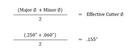
On angled tools the cutter diameter changes along the LOC. For example, Helical tool #07001, a flat-ended chamfer cutter with helical flutes, has a tip diameter of .060” and a major/shank diameter of .250”. In a scenario where it was being used to create a 60° edge break, the actual cutting action would happen somewhere between the tip and major/shank diameters. To compensate, the equation below can be used to find the average diameter along the chamfer.
Using this calculation, the effective cutter diameter is .155”, which would be used for all Speeds and Feeds calculations.
Non-linear Path
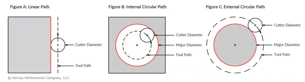
Feed rates assume a linear motion. However, there are cases in which the path takes an arc, such as in a pocket corner or a circular interpolation. Just as increasing the DOC increases the angle of engagement on a tool, so does taking a nonlinear path. For an internal corner, more of the tool is engaged and, for an external corner, less is engaged. The feed rate must be appropriately compensated for the added or lessened engagement on the tool to provide the most effective and desired IPM for the chosen application.
In the below graphic, Figure A is showcasing a linear path on a part, with a standard engagement. Figure’s B and C demonstrate the increase and decrease of engagement in non-linear, circular toolpaths. Utilizing identical feed rates between the three paths would generate three wildly different IPMs despite similar setups.
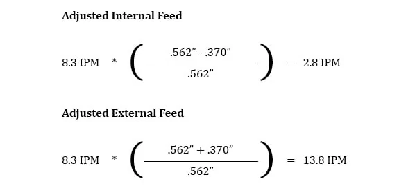
This adjustment is even more important for circular interpolation. Take, for example, a threading application involving a cutter making a circular motion about a pre-drilled hole or boss. For internal adjustment, the feed rate must be lowered to account for the additional engagement. For external adjustment, the feed rate must be increased due to less tool engagement.
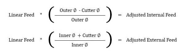
An adjustment in internal feed subtracts the differences in cutter diameters from the differences in outer diameters before dividing by the outer dia. difference. On the other hand, adjusting for external feed adds the differences between cutter diameters to the differences in inner diameters before dividing by the inner dia. difference.
Take this example, in which a Harvey Tool threadmill #70094, with a .370” cutter diameter, is machining a 9/16-18 internal thread in 17-4 stainless steel. The calculated speed is 2,064 RPM and the linear feed is 8.3 IPM. The thread diameter of a 9/16 thread is .562”, which is used for the inner and outer diameter in both adjustments. After plugging these values into the equations below, the adjusted internal feed becomes 2.8 IMP, while the external feed becomes 13.8 IPM.
SFM in Conclusion
These calculations are useful guidelines for running a cutting tool optimally in various applications and materials. However, the tool manufacturer’s recommended parameters are the best place to start for initial numbers and to set a baseline for the best tool performance.
After that, it is up to the machinist’s eyes, ears, and experience to help determine the best running parameters, which will vary by set-up, tool, machine, and chosen material. No operation is exactly the same, and nothing occurs in a vacuum. Experience and continued learning will always aid machinists in ensuring the most efficient performance possible in the cut.
The following links have the most up to date information on running parameters for Harvey Tool, Helical, Titan USA, and CoreHog CNC products.
https://www.harveyperformance.com/wp-content/uploads/2017/10/Feature-Image-Speeds-Feeds-IMG.jpg5251400Harvey Performance Companyhttp://www.harveyperformance.com/wp-content/uploads/2018/08/Logo_HarveyPerformanceCompany-4.pngHarvey Performance Company2017-10-02 17:00:172025-02-14 10:48:58Speeds and Feeds 101
In today’s manufacturing industry, titanium and its alloys have become staples in aerospace, medical, automotive, and firearm applications. This popular metal is resistant to rust and chemicals, is recyclable, and is extremely strong for its weight. However, there are several challenges that must be considered when machining titanium and selecting the appropriate tools and parameters for the job.
Titanium Varieties
Titanium is available in many varieties, including nearly 40 ASTM grades, as well as several additional alloys. Grades 1 through 4 are considered commercially pure titanium with varying requirements on ultimate tensile strength. Grade 5 (Ti6Al4V or Ti 6-4) is the most common combination, alloyed with 6 percent aluminum and 4 percent vanadium. Although titanium and its alloys are often grouped together, there are some key differences between them that must be noted before determining the ideal machining approach.
Helical Solutions’ HVTI End Mill is a great choice for high efficiency toolpaths in Titanium.
Titanium Concerns
Workholding
Although titanium may have more desirable material properties than your average steel, it also behaves more flexibly, and is often not as rigid as other metals. This requires a secure grip on titanium workpieces, and as rigid a machine setup as is possible. Other considerations include avoiding interrupted cuts, and keeping the tool in motion at all times of contact with the workpiece. Dwelling in a drilled hole or stopping a tool next to a profiled wall will cause the tool to rub – creating excess heat, work-hardening the material, and causing premature tool wear.
Heat Generation
Heat is a formidable enemy, and heat generation must be considered when selecting speeds and feeds. While commercially pure grades of titanium are softer and gummier than most of its alloys, the addition of alloying elements typically raises the hardness of titanium. This increases concerns regarding generated heat and tool wear. Maintaining a larger chipload and avoiding unnecessary rubbing aids with tool performance in the harder titanium alloys, and will minimize the amount of work hardening produced. Choosing a lower RPM, paired with a larger chipload, can provide a significant reduction in temperature when compared to higher speed options. Due to its low conduction properties, keeping temperatures to a minimum will put less stress on the tool and reduce wear. Using high-pressure coolant is also an effective method to reduce heat generation when machining titanium.
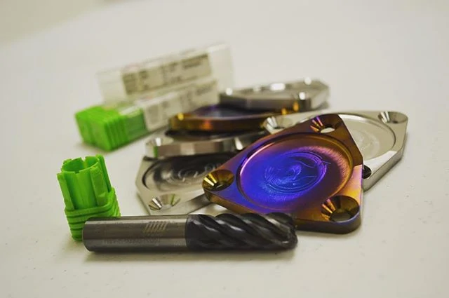
These camshaft covers were custom made in titanium for Mitsubishi Evos. Photo courtesy of @RebootEng (Instagram)
Galling and Built-Up Edge
The next hurdle to consider is that titanium has a strong tendency to adhere to a cutting tool, creating built up edge. This is a tricky issue which can be reduced by using copious amounts of high pressure coolant aimed directly at the cutting surface. The goal is to remove chips as soon as possible to prevent chip re-cutting, and keep the flutes clean and clear of debris. Galling is a big concern in the commercially pure grades of titanium due to their “gummy” nature. This can be addressed using the strategies mentioned previously, such as continuing feed at all times of workpiece contact, and using plenty of high-pressure coolant.
Titanium Solutions
While the primary concerns when machining titanium and its alloys may shift, the methods for mitigating them remain somewhat constant. The main ideas are to avoid galling, heat generation, work hardening, and workpiece or tool deflection. Use a lot of coolant at high pressure, keep speeds down and feeds up, keep the tool in motion when in contact with the workpiece, and use as rigid of a setup as possible.
In addition, selecting a proper tool coating can help make your job a successful one. With the high heat being generated during titanium machining operations, having a coating that can adequately deal with the temperature is key to maintaining performance through an operation. The proper coating will also help to avoid galling and evacuate chips effectively. Coatings such as Harvey Tool’s Aluminum Titanium Nitride (AlTiN Nano) produce an oxide layer at high temperatures, and will increase lubricity of the tool.
Tooling Solutions
Helical Solutions offers the HVTI-6 line of tooling optimized for High Efficiency Milling (HEM) in Titanium and its alloys. Helical’s HVTI-6 features its Aplus coating which offers added lubricity and high temperature resistance for improved tool life and faster speeds and feeds.
As titanium and its many alloys continue to grow in use across various industries, more machinists will be tasked with cutting this difficult material. However, heat management and appropriate chip evacuation, when paired with the correct coating, will enable a successful run and profitable tool life.
Tool entry is pivotal to machining success, as it’s one of the most punishing operations for a cutter. Entering a part in a way that’s not ideal for the tool or operation could lead to a damaged part or exhausted shop resources. Below, we’ll explore the most common part entry methods, as well as tips for how to perform them successfully.
Pre-Drilled Hole
Pre-drilling a hole to full pocket depth (and 5-10% larger than the end mill diameter) is the safest practice of dropping your end mill into a pocket. This method ensures the least amount of end work abuse and premature tool wear. It also facilitates smoother chip evacuation, reducing the risk of chip buildup and potential tool breakage. Machinists often use this technique when working with materials prone to chip welding or built-up edge formation, ensuring consistent machining performance.
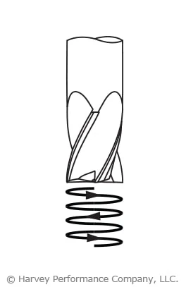
Helical Interpolation
Helical Interpolation is a very common and safe practice of tool entry with ferrous materials. Employing corner radius end mills during this operation will decrease tool wear and lessen corner breakdown. With this method, use a programmed helix diameter of greater than 110-120% of the cutter diameter. Moreover, helical interpolation offers advantages in achieving precise surface finishes, making it a preferred choice for applications requiring high precision and surface quality, such as aerospace and medical device manufacturing.
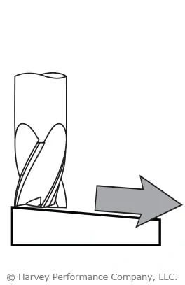
Ramping-In
This type of operation can be very successful, but institutes many different torsional forces the cutter must withstand. A strong core is key for this method, as is room for proper chip evacuation. Using tools with a corner radius, which strengthen its cutting portion, will help. Additionally, ramping-in allows for efficient material removal with reduced axial forces, minimizing workpiece distortion and enhancing dimensional accuracy. Machinists often employ this technique in contouring and pocketing operations, where maintaining part integrity is crucial.
Suggested Starting Ramp Angles:
Hard/Ferrous Materials: 1°-3°
Soft/Non-Ferrous Materials: 3°-10°
For more information on this popular tool entry method, see Ramping to Success.
Arcing
This method of tool entry is similar to ramping in both method and benefit. However, while ramping enters the part from the top, arcing does so from the side. The end mill follows a curved tool path, or arc, when milling, this gradually increasing the load on the tool as it enters the part. Additionally, the load put on the tool decreases as it exits the part, helping to avoid shock loading and tool breakage. Machinists often utilize this technique in mold making, die sinking, and 3D contouring operations, enhancing productivity and surface finish quality.
Straight Plunge
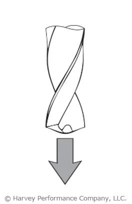
This is a common, yet often problematic method of entering a part. A straight plunge into a part can easily lead to tool breakage. If opting for this machining method, however, certain criteria must be met for best chances of machining success. The tool must be center cutting, as end milling incorporates a flat entry point making chip evacuation extremely difficult. Drill bits are intended for straight plunging, however, and should be used for this type of operation.
Straight Tool Entry
Straight entry into the part takes a toll on the cutter, as does a straight plunge. Until the cutter is fully engaged, the feed rate upon entry is recommended to be reduced by at least 50% during this operation. Machinists often resort to straight tool entry in simple machining operations with limited tool access or where other entry methods are impractical. However, it’s crucial to monitor tool wear and chip evacuation carefully to prevent chip buildup and potential tool breakage. Adjusting cutting parameters based on material properties and part geometry can further enhance machining efficiency and tool life.
Roll-In Tool Entry
Rolling into the cut ensures a cutter to work its way to full engagement and naturally acquire proper chip thickness. The feed rate in this scenario should be reduced by 50%. Roll-in tool entry is particularly advantageous in slotting and profiling operations, where maintaining consistent chip thickness is critical for surface finish quality and dimensional accuracy. Machinists often utilize this technique in high-speed machining applications, maximizing material removal rates while minimizing tool wear and heat generation.
Mastering various tool entry techniques is essential for machining success. By understanding and implementing these methods effectively, machinists can optimize performance while prolonging the lifespan of their tools. Continual evaluation of cutting conditions and adaptation of entry strategies based on material properties and part geometry are key to achieving superior machining results.
https://www.harveyperformance.com/wp-content/uploads/2017/07/Feature-Image-Tool-Entry-IMG.jpg5251400Harvey Performance Companyhttp://www.harveyperformance.com/wp-content/uploads/2018/08/Logo_HarveyPerformanceCompany-4.pngHarvey Performance Company2017-07-17 14:53:062024-03-20 11:54:31Most Common Methods of Tool Entry
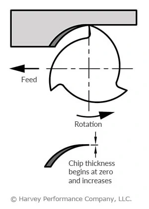
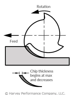
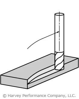
There are two distinct ways to cut materials when CNC milling: Conventional Milling (Up) and Climb Milling (Down). The difference between these two techniques is the relationship of the rotation of the cutter to the direction of feed. In Conventional Milling, the cutter rotates against the direction of the feed. During Climb Milling, the cutter rotates with the feed.
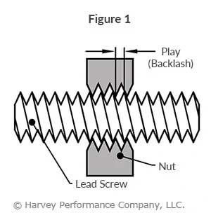
Conventional Milling is the traditional approach when cutting because the backlash, or the play between the lead screw and the nut in the machine table, is eliminated as seen in Figure 1 below. Recently, however, Climb Milling has been recognized as the preferred way to approach a workpiece since most machines today compensate for backlash or have a backlash eliminator.
Key Conventional and Climb Milling Properties:
Conventional Milling (Figure 2)
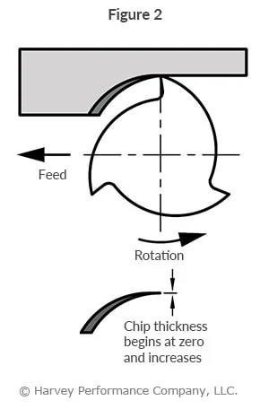
As previously stated, traditionally conventional milling has been the common choice for most machinists. This is where the cutting edge of the tool is actually rotating away from the direction of the feed. An example of this is seen in Figure 2 below. Until recently, this has been the common choice due to backlash however, the rise of climb milling has caused machinists or machines to adapt and compensate for this issue.
That is not to say there aren’t benefits to climb milling. For example, this strategy offers a machinist more control and less vibration than its climb milling counterpart. Similarly, for materials that traditionally chatter or tear, conventional milling would be the proper strategy to choose. On the other hand, here are some reasons why it might be most beneficial to adopt a climb milling strategy:
Chip width starts from zero and increases which causes more heat to diffuse into the workpiece and produces work hardening
Tool rubs more at the beginning of the cut causing faster tool wear and decreases tool life
Chips are carried upward by the tooth and fall in front of cutter creating a marred finish and re-cutting of chips
Upwards forces created in horizontal milling* tend to lift the workpiece, more intricate and expansive work holdings are needed to lessen the lift created*
Climb Milling (Figure 3)
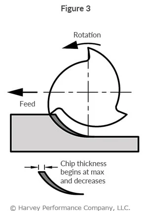
As machinists are always trying to find ways to increase efficiency and tool life, climb milling has gotten a lot of recent traction in the space. Less heat is generated within the tool, and friction is more easily mitigated. These two alone lead to longer tool life, allowing for more parts completed per tool, lowering a shops bottom line. Also, climb milling can lead to a better surface finish due to how the chips are formed at the cutting edge.
With more modern machines now compensating for backlash or utilize backlash eliminators, it has become a much easier strategy to adopt within shops. While we went over some reasons why climb milling is not an effective strategy above, here are some reasons why a machinist may want to explore climb milling:
Chip width starts from maximum and decreases so heat generated will more likely transfer to the chip
Creates cleaner shear plane which causes the tool to rub less and increases tool life
Chips are removed behind the cutter which reduces the chance of chip recutting
Downwards forces in horizontal milling is created that helps hold the workpiece down, less complex work holdings are need when coupled with these forces
Horizontal milling is when the center line of the tool is parallel to the work piece
When to Choose Conventional or Climb Milling
Climb Milling is generally the best way to machine parts today since it reduces the load from the cutting edge, leaves a better surface finish, and improves tool life. During Conventional Milling, the cutter tends to dig into the workpiece and may cause the part to be cut out of tolerance.
However, though Climb Milling is often the current preferred way to machine parts, there are times when Conventional Milling is the necessary milling style. One such example is if your machine does not counteract backlash. In this case, Conventional Milling should be implemented. Without accounting for backlash, breakage can occur due to the forces within the machine during tool engagement.
In addition, conventional milling should also be utilized on casting, forgings or when the part is case hardened. This is due to the cut beginning under the surface of the material, where it will gradually build a chip. Climb milling into these materials will see maximum chip thickness on engagement, which could lead to premature failure of the cutting edge due to the forces generated.
The following is just one of several blog posts relevant to High Efficiency Milling. To achieve a full understanding of this popular machining method, view any of the additional HEM posts below!
Chip Thinning is a phenomenon that occurs with varying Radial Depths Of Cut (RDOC), and relates to chip thickness and feed per tooth. While these two values are often mistaken as the same, they are separate variables that have a direct impact on each other.
Radial Depth of Cut
Radial Depth of Cut denotes the distance that a tool advances into a workpiece, also known as Stepover, Cut Width, or XY.
Feed Per Tooth
Feed per tooth translates directly to your tool feed rate, and is commonly referred to as Inches Per Tooth (IPT) or chip load.
Chip Thickness
Chip thickness is often overlooked. It refers to the actual thickness of each chip cut by a tool, measured at its largest cross-section. Users should be careful not to confuse chip thickness and feed per tooth, as these are each directly related to the ideal cutting conditions.
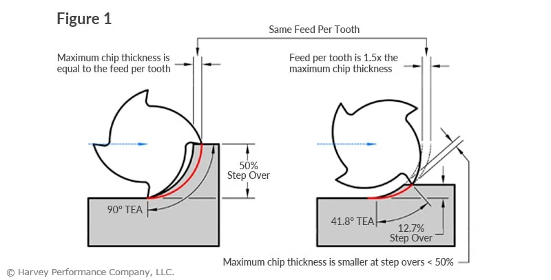
When using a 50% step over (left side of Figure 1), the chip thickness and feed per tooth are equal to each other. Each tooth will engage the workpiece at a right angle, allowing for the most effective cutting action, and avoiding rubbing as much as possible. Once the RDOC falls below 50% of the cutter diameter (right side of Figure 1), the maximum chip thickness decreases, in turn changing the ideal cutting conditions of the application. This can lead to poor part finish, inefficient cycle times, and premature tool wear. Properly adjusting the running parameters can greatly help reduce these issues.
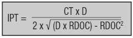
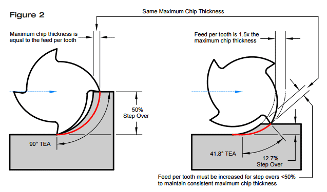
The aim is to achieve a constant chip thickness by adjusting the feed rate when cutting at different RDOC. This can be done with the following equation using the Tool Diameter (D), RDOC, Chip Thickness (CT), and Feed Rate (IPT). For chip thickness, use the recommended value of IPT at 50% step over. Finding an adjusted feed rate is as simple as plugging in the desired values and solving for IPT. This keeps the chip thickness constant at different depths of cut. The adjustment is illustrated in Figure 2.
Inches Per Tooth (Chip Thinning Adjustment)
Lasting Benefits
In summary, the purpose of these chip thinning adjustments is to get the most out of your tool. Keeping the chip thickness constant ensures that a tool is doing as much work as it can within any given cut. Other benefits include: reduced rubbing, increased material removal rates, and improved tool life.
https://www.harveyperformance.com/wp-content/uploads/2017/03/Feature-Image-Chip-Thinning-IMG-1.jpg5251400Tom Pylehttp://www.harveyperformance.com/wp-content/uploads/2018/08/Logo_HarveyPerformanceCompany-4.pngTom Pyle2017-03-13 18:49:392024-02-27 10:32:43How to Combat Chip Thinning