Every machinist must be aware of tool deflection, as too much deflection can lead to catastrophic failure in the tool or workpiece. Deflection is the displacement of an object under a load causing curvature and/or fracture.
For Example: When looking at a diving board at rest without the pressure of a person’s weight upon it, the board is straight. But as the diver progresses down further to the end of the board, it bends further. Deflection in tooling can be thought of in a similar way.
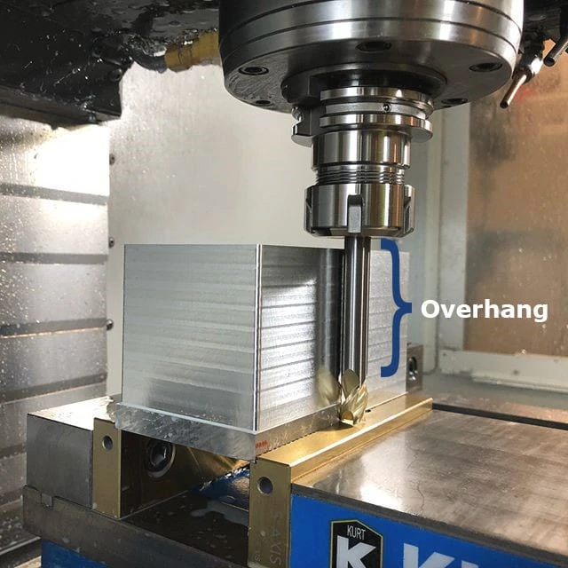
Overhang refers to the distance a tool is sticking out of the tool holder. Simply, as overhang increases, the tool’s likelihood of deflection increases. The larger distance a tool hangs out of the holder, the less shank there is to grip, and depending on the shank length, this could lead to harmonics in the tool that can cause fracture. Simply put, For optimal working conditions, minimize overhang by chucking the tool as much as possible.
Another way to minimize deflection is having a full grasp on the differences between a long flute and a long reach tool. The reason for such a difference in rigidity between the two is the core diameter of the tool. The more material, the more rigid the tool; the shorter the length of flute, the more rigid the tool and the longer the tool life. While each tooling option has its benefits and necessary uses, using the right option for an operation is important.
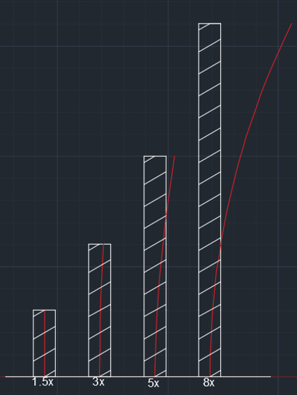
The below charts illustrate the relationship between force on the tip and length of flute showing how much the tool will deflect if only the tip is engaged while cutting. One of the key ways to get the longest life out of your tool is by increasing rigidity by selecting the smallest reach and length of cut on the largest diameter tool.
Reached tools are typically used to remove material where there is a gap that the shank would not fit in, but a noncutting extension of the cutter diameter would. This length of reach behind the cutting edge is also slightly reduced from the cutter diameter to prevent heeling (rubbing of noncutting surface against the part). Reached tools are one of the best tools to add to a tool crib because of their versatility and tool life.
Long Flute tools have longer lengths of cut and are typically used for either maintaining a seamless wall on the side of a part, or within a slot for finishing applications. The core diameter is the same size throughout the cutting length, leading to more potential for deflection within a part. This possibly can lead to a tapered edge if too little of the cutting edge is engaged with a high feed rate. When cutting in deep slots, these tools are very effective. When using HEM, they are also very beneficial due to their chip evacuation capabilities that reached tools do not have.
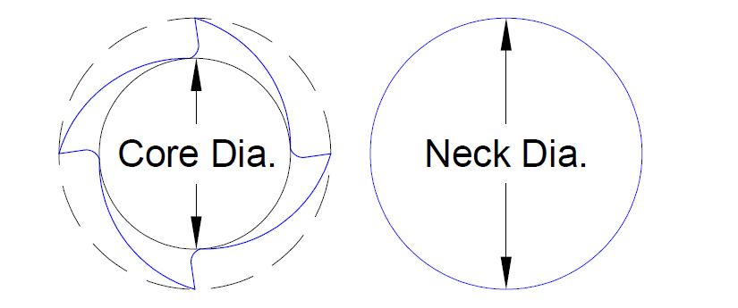
Diameter is an important factor when calculating deflection. Machinists oftentimes use the cutter diameter in the calculation of long flute tools, when in actuality the core diameter (shown below) is the necessary dimension. This is because the fluted portion of a tool has an absence of material in the flute valleys. For a reached tool, the core diameter would be used in the calculation until its reached portion, at which point it transitions to the neck diameter. When changing these values, it can lower deflection to a point where it is not noticeable for the reached tool but could affect critical dimensions in a long flute tool.
Deflection Summarized
Tool deflection can cause damage to your tool and scrap your part if not properly accounted for prior to beginning a job. Be sure to minimize the distance from the tool holder to the tip of the tool to keep deflection to a minimum. For more information on ways to reduce tool deflection in your machining, view Diving into Depth of Cut.
https://www.harveyperformance.com/wp-content/uploads/2018/05/Featured-Image-Tool-Deflection-IMG.jpg5251400Jacob Concepcionhttp://www.harveyperformance.com/wp-content/uploads/2018/08/Logo_HarveyPerformanceCompany-4.pngJacob Concepcion2018-05-03 09:42:392024-03-05 16:25:18Tool Deflection & Its Remedies
Aluminum is one of the most commonly machined materials, as most forms of the material feature excellent machinability, and is thus a commonly used material in manufacturing. Because of this, the competition for aluminum machining can be intense. Understanding the basics behind tool selection, running parameters, and advanced milling techniques for aluminum can help machinists earn a competitive advantage.
Material Properties
Aluminum is a highly formable, workable, lightweight material. Parts made from this material can be found in nearly every industry. Additionally, Aluminum has become a popular choice for prototypes due to its low-cost and flexibility.
Aluminum is available in two basic forms: Cast and Wrought. Wrought Aluminum is typically stronger, more expensive, and contains a lower percentage of outside elements in its alloys. Wrought Aluminum is also more heat-resistant than Cast and has a higher level of machinability.
Cast Aluminum has less tensile strength but with a higher flexibility. It costs less, and has higher percentages of outside elements (silicon, magnesium, etc.) in its alloys, making it more abrasive than Wrought.
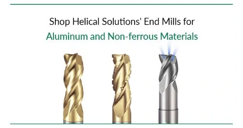
There are a few coating options available for Aluminum tooling, including the popular gold-colored ZrN (Zirconium Nitride) and the lesser known but highly effective TiB2 (Titanium Diboride). Uncoated tooling can also provide solid machining performance. However, the real key to high performance machining in Aluminum is knowing the proper flute count and helix angle required for your operation.
Flute Count
End mills for aluminum are often available in either 2 flute or 3 flute styles. With higher flute counts, it would become difficult to evacuate chips effectively at the high speeds at which you can run in aluminum. This is because aluminum alloys leave a large chip, and chip valleys become smaller with each additional flute on an end mill.
Traditionally, 2 flute end mills have been the preferred choice for Aluminum. However, 3 flute end mills have proven to be more successful in many finishing operations, and with the right parameters they can also work successfully as roughers. While much of the debate between 2 and 3 flute end mills for Aluminum boils down to personal preference, the operation, rigidity, and desired material removal rates can also have an effect on tool selection.
Helix Angles
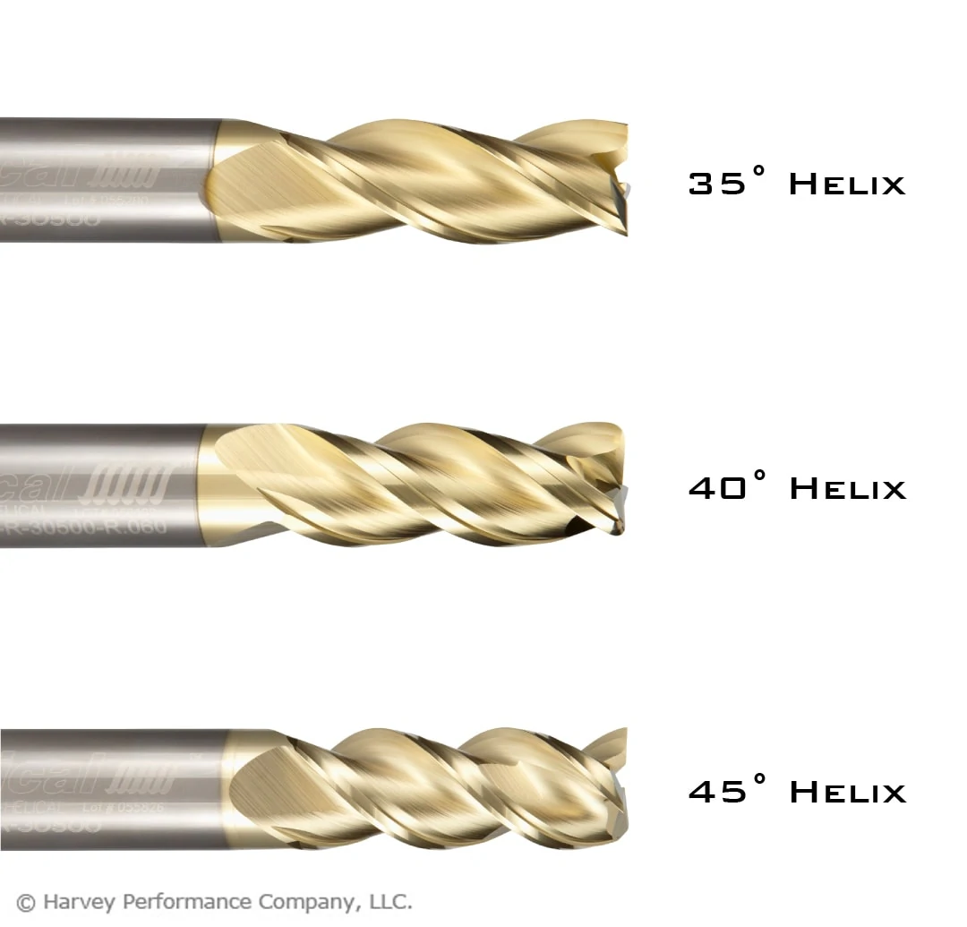
The helix angle of a tool is measured by the angle formed between the centerline of the tool and a straight line tangent along the cutting edge. Cutting tools for aluminum typically feature higher helix angles than standard end mills. Specialized helix angles for Aluminum are typically either 35°, 40°, or 45°. Variable helix tools are also available and make a great choice for reducing chatter and harmonics while also increasing material removal rates.
A helix angle of 35° or 40° is a good choice for traditional roughing and slotting applications. A 45° helix angle is the preferred choice for finishing, but also for High Efficiency Milling toolpaths as the high helix angle wraps around the tool faster and makes for a more aggressive cut.
Tooling Options
When machining aluminum, standard 2 or 3 flute tools will often get the job done. However, for certain applications and machine setups there are some more tooling options to consider for even better performance.
Chipbreaker Tooling
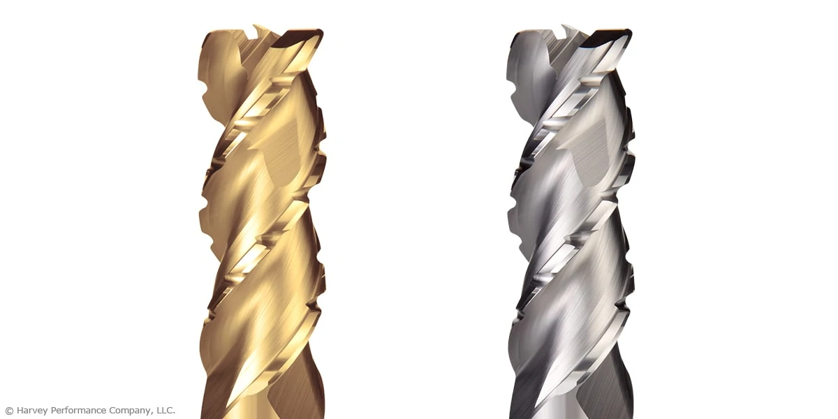
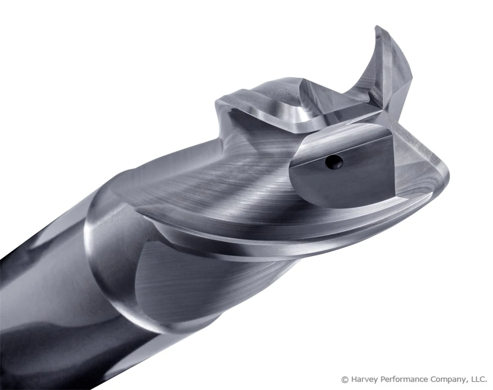
One of the most important things to consider when machining aluminum (and many other materials) is effective chip evacuation. Standard 2-3 flute end mills running at recommended speeds and feeds and proper chip loads can evacuate chips fairly well. However, 3 flute chipbreaker tooling can run at increased speed and feed rates for even better performance. The unique offset chip breaker geometry creates smaller chips for optimal evacuation while still leaving a semi-finished surface.
These tools are excellent for more advanced toolpaths like High Efficiency Milling, which is another important tool for a successful aluminum machining experience.
High Balance End Mills
High balance end mills are designed to significantly increase performance in highly balanced machining centers capable of elevated RPMs and feed rates. These tools are precision balanced specifically for high velocity machining in aluminum (up to 33,000 RPM).
Helical Solutions offers high balance tooling in standard 2 flute styles, as well as coolant-through 3 flute styles for reduced heat, enhanced chip evacuation, and increased material removal rates. These tools, like the chipbreakers, are also an excellent choice for High Efficiency Milling toolpaths.
Running Parameters
Setting the right parameters for aluminum applications is vital to optimizing productivity and achieving better machining results. Since aluminum is an easier material to machine, pushing your machine to its limits and getting the most out of your tool is vital to stay ahead of the competition and keep winning business.
While there are many factors that go into the parameters for every job, there are some general guidelines to follow when machining aluminum. For cast aluminum alloys (i.e. 308, 356, 380), a surface footage of 500-1000 SFM is recommended, with RPMs varying based on cutter diameter. The basic calculation to find a starting point for RPMs would be (3.82 x SFM) / Diameter.
In wrought aluminum alloys (i.e. 2024, 6061, 7075), a surface footage of 800-1500 SFM is recommended, with the same calculation being used to find a starting point for RPMs.
High Efficiency Milling
High Efficiency Milling, commonly known as HEM, is a strategy that is rapidly gaining popularity in the manufacturing industry. Many CAM programs are now including HEM toolpaths, and while virtually any machine can perform HEM, the CNC controller must feature a fast processor to keep up with the additional lines of code. A great example of High Efficiency Milling toolpaths in Aluminum can be seen below.
At its core, HEM is a roughing technique that utilizes a low Radial Depth of Cut (RDOC) and a high Axial Depth of Cut (ADOC) to take full advantage of the cutting edge of the tool. To learn more about how High Efficiency Milling can increase your efficiency, extend your tool life to keep costs down, and get greater performance for aluminum (and other materials), click here to download the HEM Guidebook.
In Summary
Aluminum is a versatile material with a high level of machinability, but it should not be overlooked. Understanding the best ways to tackle it is important for achieving the desired results. Optimizing your tool crib, machine setups, and toolpaths for aluminum is essential to stay ahead of the competition and make your shop more efficient.
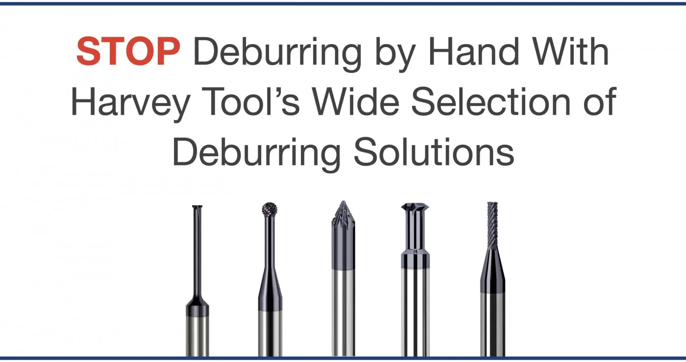
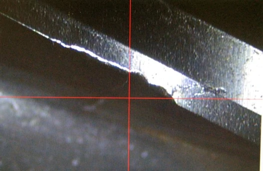
Deburring is a process in which sharp edges and burrs are removed from a part to create a more aesthetically pleasing final product. After milling, parts are typically taken off the machine and sent off to the Deburring Department. Here, the burrs and sharp points are removed, traditionally by hand. However, an operation that takes an hour by hand can be reduced to mere minutes by deburring parts right in the machine with high precision CNC deburring tools, making hand deburring a thing of the past.
High Precision Tools
Hand deburring tools often have a sharp hook-shaped blade on the end, which is used to scrape/slice off the burrs as it passes along the edge of the part. These tools are fairly simple and easy to use, but much less efficient and precise than CNC deburring tools.
CNC deburring tools are also held to much tighter tolerances than traditional hand-deburring tools. Traditional cylindrical deburring tools typically have a diameter-tolerance window of +/- .008 versus a CNC deburring end mill which has a diameter tolerance of +/-.0005. The tighter tolerance design eliminates the location issues found in traditional deburring tools with loose tolerances, allowing them to be programmed like a traditional end mill.
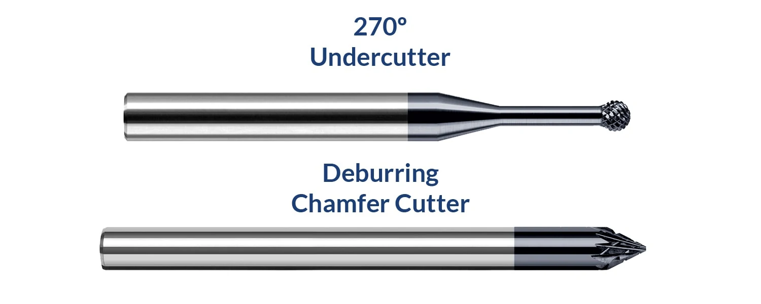
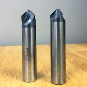
While hand deburring tools often have just a single blade, CNC deburring tools feature double cut patterns and a high number of flutes. The double cut pattern contains both right hand and left hand teeth, which results in an improved finish. These tools leave completed parts looking far superior to their hand-deburred counterparts, with more consistent and controlled edge breaks. Additionally, there is a large variety of CNC deburring tools available today which can take full advantage of multi-axis machines and the most complex tool paths. For example, Harvey Tool’s 270° Undercutting End Mill is a great choice for multi-axis and more complex deburring options. Further, Deburring Chamfer Cutters are multi-use tools that can perform both chamfering and deburring accurately with no need for a tool change.
Reduce Production Costs and Increase Profits
Having an entire department dedicated to deburring can be costly, and many smaller businesses may have pulled employees off other jobs to help with deburring, which hampers production. Taking employees off the deburring station and asking them to run more parts or man another department can help keep labor costs low while still increasing production rates.
Stop Deburring By Hand and Increase Your Profits
By deburring right in the CNC machine, parts can be completed in one machining operation. The double-cut pattern found on many deburring tools also allows for increased speeds and feeds. This helps to reduce cycle times even further, saving hours of work and increasing production efficiency. Deburring in the machine is a highly repeatable process that reduces overall cycle times and allows for more efficient finishing of a part. In addition, CNC machines are going to be more accurate than manual operations, leading to fewer scrapped parts due to human error and inconsistencies.
Simply put, the precision and accuracy of the CNC machine, along with the cost and time savings associated with keeping the part in the machine from start to finish, makes deburring in the CNC machine one of the easiest way to increase your shop’s efficiency.
https://www.harveyperformance.com/wp-content/uploads/2018/03/Feature-Image-Stop-Deburring-by-Hand-IMG-1.jpg5251400Harvey Performance Companyhttp://www.harveyperformance.com/wp-content/uploads/2018/08/Logo_HarveyPerformanceCompany-4.pngHarvey Performance Company2018-03-13 16:26:182024-02-12 14:37:41Why You Should Stop Deburring by Hand
In today’s ultracompetitive industry, every machine shop seeks even the slightest edge to gain an advantage on their competition and boost their bottom line. However, what many machinists don’t know is that improving their shop’s efficiency might be easier than they thought. The following five ways your shop is inefficient will provide a clear starting point of where to look for machinists desperate to earn a competitive edge.
Premature Tool Decay / Tool Failure
If you’re finding that your tools are failing or breaking at an unacceptable rate, don’t mistake it for commonplace. It doesn’t have to be. Prolonging the life of your tooling starts with finding not just the right tool, but the best one; as well as running it in a way to get its optimal performance. Many machinists mistake premature tool failure with running parameters that were too aggressive. In fact, not pushing the tool to its full potential can actually cause it to decay at an accelerated rate in certain situations.
Tool failure can occur in many different ways: Abrasive Wear, Chipping, Thermal Cracking or Tool Fracture, just to name a few. Understanding each type and its causes can help you to quickly boost your shop’s efficiency by minimizing downtime and saving on replacement tool costs.
Your shop spends money to employ machinists, run machines, and buy cutting tools. Get your money’s worth, lead the industry, and ensure that you’re providing your customers with the highest quality product. Not only will this help to keep your buyer-seller relationship strong, but it will allow you the flexibility to increase your prices in the future, and will attract prospective customers.
Many factors influence part finish, including the material and its hardness, the speeds and feeds you’re running your tool at, tool deflection, and the tool-to-workpiece orientation.
One often forgotten expense of a machine shop is coolant – and it can be pricey. A 55-gallon drum of coolant can run more than $1,500. What’s worse is that coolant is often applied in excess of what’s required for the job. In fact, some machines even feature a Minimum Quantity Lubricant (MQL) functionality, which applies coolant as an extremely fine mist or aerosol, providing just enough coolant to perform a given operation effectively. While drowning a workpiece in coolant, known as a “Flood Coolant,” is sometimes needed, it is oftentimes utilized on jobs that would suffice with much less.
Did you know that several CNC cutting tools can perform multiple operations? For example, a Chamfer Mill can chamfer, bevel, deburr, and countersink. Some Chamfer Mills can even be used as a Spotting Drill. Of course, the complexity of the job will dictate your ability to reap the benefits of a tool’s versatility. For instance, a Spotting Drill is obviously the best option for spotting a hole. If performing a simple operation, though, don’t go out of your way to buy additional tooling when what’s already in your carousel can handle it.
What use is a machine that’s not running beside making your shop inefficient? Minimizing machine downtime is a key way to ensure that your shop is reaching its efficiency pinnacle. This can be accomplished a variety of ways, including keeping like-parts together. This allows for a simple swap-in, swap-out of material to be machined by the same cutting tool. This saves valuable time swapping out tooling, and lets your machine to do its job for more time per workday. Production planning is a key factor to running an efficient machine shop.
https://www.harveyperformance.com/wp-content/uploads/2018/03/Featured-Image-Shop-Inefficient-IMG.jpg5251400Harvey Performance Companyhttp://www.harveyperformance.com/wp-content/uploads/2018/08/Logo_HarveyPerformanceCompany-4.pngHarvey Performance Company2018-03-05 14:30:062023-10-12 14:34:385 Ways Your Shop is Inefficient
Coolant in purpose is widely understood – it’s used to temper high temperatures common during machining, and aid in chip evacuation. However, there are several types and styles, each with its own benefits and drawbacks. Knowing which cnc coolant – or if any – is appropriate for your job can help to boost your shop’s profitability, capability, and overall machining performance.
Coolant or Lubricant Purpose
Coolant and lubricant are terms used interchangeably, though not all coolants are lubricants. Compressed air, for example, has no lubricating purpose but works only as a cooling option. Direct coolants – those which make physical contact with a part – can be compressed air, water, oil, synthetics, or semi-synthetics. When directed to the cutting action of a tool, these can help to fend off high temperatures that could lead to melting, warping, discoloration, or tool failure. Additionally, coolant can help evacuate chips from a part, preventing chip recutting and aiding in part finish.
Coolant can be expensive, however, and wasteful if not necessary. Understanding the amount of coolant needed for your job can help your shop’s efficiency.
CNC coolant is delivered in several different forms – both in properties and pressure. The most common forms include air, mist, flood coolant, high pressure, and Minimum Quantity Lubricant (MQL). Choosing the wrong pressure can lead to part or tool damage, whereas choosing the wrong amount can lead to exhausted shop resources.
Air: Cools and clears chips, but has no lubricity purpose. Air coolant does not cool as efficiently as water or oil-based coolants. For more sensitive materials, air coolant is often preferred over types that come in direct contact with the part. This is true with many plastics, where thermal shock – or rapid expansion and contraction of a part – can occur if direct coolant is applied.
Mist: This type of low pressure coolant is sufficient for instances where chip evacuation and heat are not major concerns. Because the pressure applied is not great in a mist, the part and tool do not undergo additional stresses.
Flood: This low pressure method creates lubricity and flushes chips from a part to avoid chip recutting, a common and tool damaging occurrence.
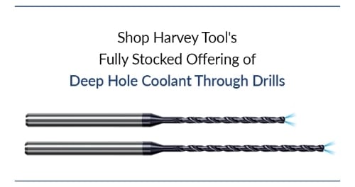
High Pressure: Similar to flood coolant, but delivered in greater than 1,000 psi. This is a great option for chip removal and evacuation, as it blasts the chips away from the part. While this method will effectively cool a part immediately, the pressure can be high enough to break miniature diameter tooling. This method is used often in deep pocket or drilling operations, and can be delivered via coolant through tooling, or coolant grooves built into the tool itself. Harvey Tool offers Coolant Through Drills, while Titan USA proudly offers Coolant-Fed ThreadMills
Minimum Quantity Lubricant (MQL): Every machine shop focuses on how to gain a competitive advantage – to spend less, make more, and boost shop efficiency. That’s why many shops are opting for MQL, along with its obvious environmental benefits. Using only the necessary amount of coolant will dramatically reduce costs and wasted material. This type of lubricant is applied as an aerosol, or an extremely fine mist, to provide just enough coolant to perform a given operation effectively.
To see all of these coolant styles in action, check out the video below from our partners at CimQuest.
In Conclusion
CNC coolant is all-too-often overlooked as a major component of a machining operation. The type of coolant or lubricant, and the pressure at which it’s applied, is vital to both machining success and optimum shop efficiency. Coolant can be applied as compressed air, mist, in a flooding property, or as high pressure. Certain machines also are MQL able, meaning they can effectively restrict the amount of coolant being applied to the very amount necessary to avoid being wasteful.
https://www.harveyperformance.com/wp-content/uploads/2017/12/Feature-Image-Coolant-for-CNC-Machining-IMG.jpg5251400Harvey Performance Companyhttp://www.harveyperformance.com/wp-content/uploads/2018/08/Logo_HarveyPerformanceCompany-4.pngHarvey Performance Company2017-12-05 15:09:342022-04-20 16:52:22What You Need to Know About Coolant for CNC Machining
Chipbreaker End Mills feature unique notch profiles, creating a serrated cutting edge. These dividers break otherwise long, stringy chips into small, easily-managed swarf that can be cleanly evacuated from the part. But why is a chipbreaker necessary for some jobs, and not others? How does the geometry of this unique tool impact its proper running parameters? In this post, we’ll answer these questions and others to discover the very real benefits of this unique cutting geometry.
How Chipbreaker Tooling Works
As a tool rotates and its cutting edge impacts a workpiece, material is sheared off from a part, creating chips. When that cutting process is interrupted, as is the case with breaks in the cutting portion of the tool, chips become smaller in length and are thus easier to evacuate. Because the chipbreakers are offset flute-to-flute, a proper, flat surface finish is achieved as each flute cleans up any excess material left behind from previously passed flutes.
Benefits of Chipbreaker Tooling
Machining Efficiency
When chips are removed from the part, they begin to pile in the machine. For extensive operations, where a great deal of material is hogged out, chip accumulation can very rapidly get in the way of the spindle or part. With larger chips, accumulation occurs much faster, leaving machinists to stop their machine regularly to remove the waste. As any machinist knows, a stopped machine equates to lost money.
Prolonged Tool Life
Inefficient chip evacuation can lead to chip recutting, or when the the tool impacts and cuts chips left behind during the machining process. This adds stresses on the tool and accelerates rate of wear on the cutting edge. Chipbreaker tooling creates small chips that are easily evacuated from a part, thus minimizing the risk of recutting.
Accelerated Running Parameters
A Harvey Performance Company Application Engineer recently observed the power of a chipbreaker tool firsthand while visiting a customer’s shop in Minnesota. The customer was roughing a great amount of 4340 Steel. Running at the parameters below, the tool was able to run uninterrupted for two hours!
Chipbreaker geometry, or grooves within the cutting face of the tool, break down chips into small, manageable pieces during the machining process. This geometry can boost shop efficiency by minimizing machine downtime to clear large chips from the machining center, improve tool life by minimizing cutting forces exerted on the tool during machining, and allow for more accelerated running parameters.
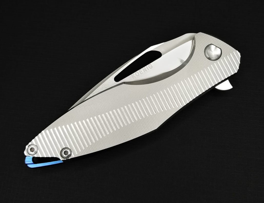
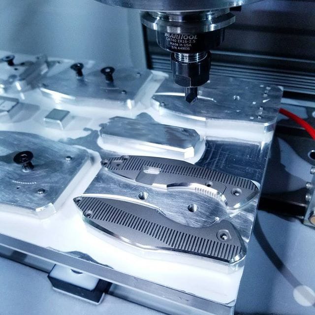
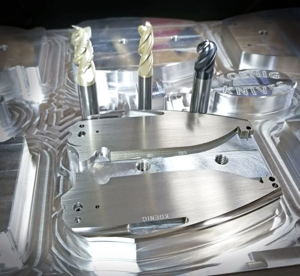
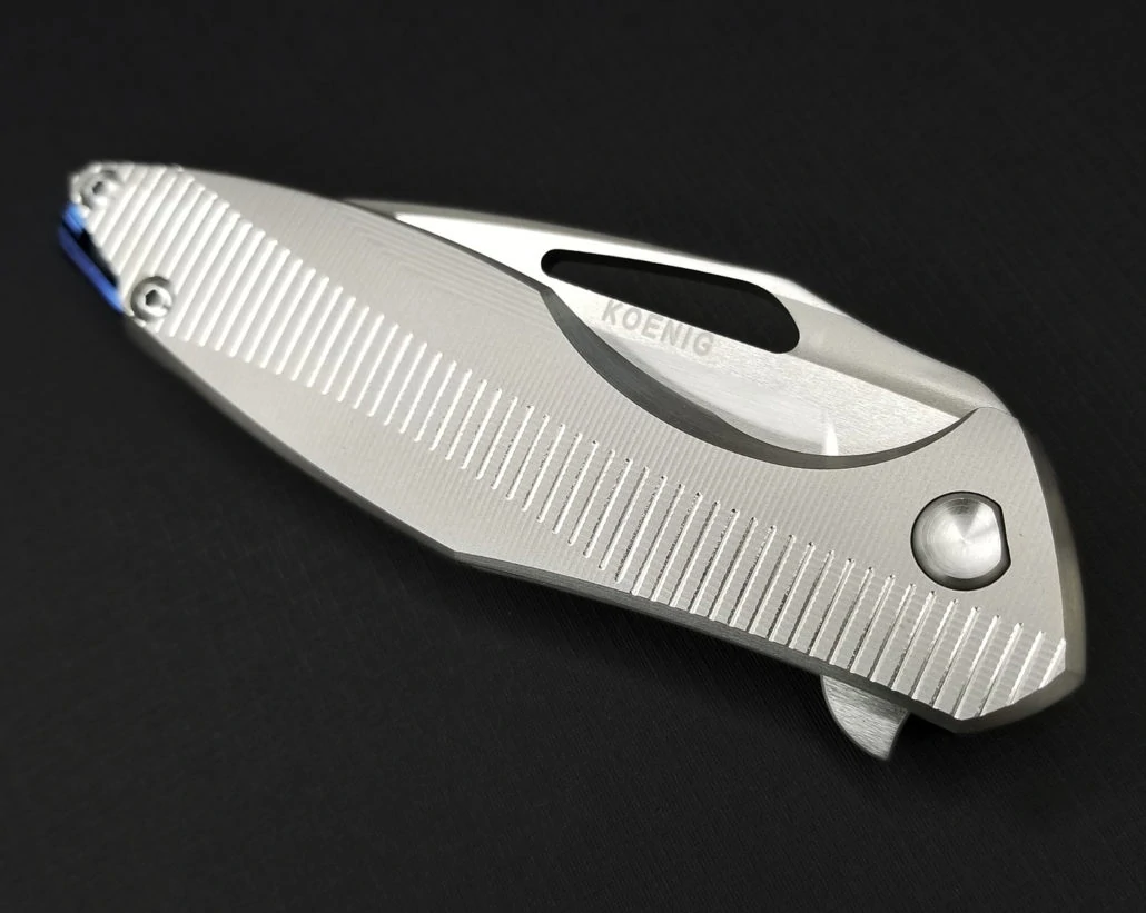
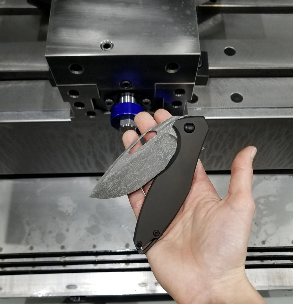
Koenig Knives is a fast-growing, Idaho-based knife manufacturer, recognized by many as one of the premier knife-making companies in the market today. Bill Koenig started the company back in 2013, using his off-days in between his long shifts working the oil fields in North Dakota to build the business. After 3 years of exploring the craft, building a presence in the market, and saving money, Koenig was able to lease a work space, buy his first Haas machine, and start manufacturing his knives right here in America. The Koenig Knives team has now expanded to include four more employees: Krista, the Director of Operations, Cameron, the Lead Machinist, Doug in Assembly, and Todd, who works on finishing. Koenig Knives is quickly becoming known for their focus on quality, innovation, and consistency, backing all of their knives with a lifetime warranty.
We talked with both Bill and Cameron for this latest Featured Customer profile, exploring the world of CNC knifemaking, how they use High Efficiency Milling (HEM) to improve their machining efficiency, and the effect that the machining community on social media has had on their business.
Photo Courtesy of: Koenig Knives
Tell us about your business and how you got started.
Bill: Koenig Knives was started in 2013. I have always been passionate about knives, starting when I was in the Boy Scouts as a young boy. This passion turned to obsession and I went from a collector/enthusiast to a knife manufacturer in December of 2013 when we released our first batch of knives.
Originally we used an off-site manufacturer, who we worked closely with from 2013 until mid-2016. We continued to grow rapidly, and that is when I made the decision to start handling all manufacturing ourselves. We took delivery of our first machine, a Haas VF2SS, at the end of 2016. The rest is history.
What made you get into machining?
Cameron: I started as a CNC operator at an assault rifle manufacturer. After seeing raw material being machined into a beautiful, functioning gun, I decided to make machining my career and I have never looked back.
What sort of machines do you use in your shop?
Cameron: We currently have two Haas VF2SS machines and an Okamoto.
Which materials do you work with in your shop?
Cameron: We work with wide range of materials, including Grade 5 Titanium, Timascus, Damascus, Carbon Fiber, Micarta, Tool Steel , 6061 Aluminum , CTS-XHP, CTS-204P, and 416 Stainless Steel.
Photo Courtesy of: Koenig Knives
What sets Koenig Knives apart from the competition?
Bill: We are often asked what category we would place ourselves in, whether it be production, custom etc. I always hesitate when answering because I can’t think of a way to categorize Koenig Knives besides “high end production with custom offerings.” We have a high end production line, but we also offer the ability to order your own customized version of one of our knives. This is something that is not too common in the industry. Quality, customer service and innovation are our main goals as a company, and we feel we have done a great job hitting on all three.
What is the most challenging part of the knife-making machining process?
Cameron: I think what makes the machining process unique with our product is the fact that we use some of the most cutting edge steel alloys for our blades. It becomes more challenging because these steel alloys are constantly advancing. Finding the perfect harmony of machining parameters for some of the relatively newer steels can be a challenge at times.
Why is high quality tool performance important to you?
Cameron: When part finishes are extremely crucial and there’s a high quantity of parts needed, having high quality tooling like Helical is essential. Helical tools help us maintain a much higher machining efficiency because of the outstanding tool life, while also achieving more aggressive run times. In addition, we are able to consistently keep high tolerances, resulting in a better final product.
Photo Courtesy of: Koenig Knives
What is your favorite process to work on as a machinist?
Cameron: I love everything about this career, except cleaning the coolant tank. I could do without that…
Koenig Knives has a great Instagram following. Tell us more about how the machinist social media community has helped grow your business.
Cameron: The machinist social media community has helped us connect with various knife makers all over the world. We learn from each other by sharing techniques and helpful tips, and we inspire each other by sharing our creations online. The machinist community on Instagram has been great – we would recommend any business, even the smallest job shops, to take a look at starting their own accounts.
Why is manufacturing your products in America important to you?
Bill: Buying American has always been very important to me for many reasons. The sense of supporting fellow American workers was instilled in me at a young age. When I started Koenig Knives, I wanted to make sure everything from the screws to the boxes was made in the US.
Photo Courtesy of: Koenig Knives
Tell us about your favorite project that Helical helped to create.
Cameron: Machining the Arius blades (pictured above) has been my favorite on-going project. Once we switched to all Helical tools, it drastically improved our run times and blade finish, and created an incredible final product.
Have you used High Efficiency Milling techniques in your shop?
Cameron: Absolutely! We couldn’t do without HEM!
What advice do you have for other machinists who want to try High Efficiency Milling?
Cameron: Machining Advisor Prois an absolute game changer when it comes to HEM, as well as for general machining solutions. The technical milling strategies and information that Helical makes available give machinists everything they need to be successful. When a machinist has a full understanding of what is taking place and what is needed to efficiently and correctly cut material, the sky is the limit.
If you could give one piece of advice to a new machinist ready to take the #PlungeIntoMachining, what would it be?
Cameron: With machining technology advancing at the amazing rate that it is, there is no better time to become a machinist. It is a trade that is constantly improving, and offers so many opportunities for young people.
Photo Courtesy of: Koenig Knives
Would you like to be considered for a future “Featured Customer” blog? Click here to submit your information.
NOTE: This article covers speeds and feed rates for milling tools, as opposed to turning tools.
Before using a cutting tool, it is necessary to understand tool cutting speeds and feed rates, more often referred to as “speeds and feeds.” Speeds and feeds are the cutting variables used in every milling operation and vary for each tool based on cutter diameter, operation, material, etc.
Understanding the right speeds and feeds for your tool and operation before you start machining is critical. These are to be used to set baselines for a particular tool, ensuring proper performance without compromising part finish and tool life.
NOTE: This article covers speeds and feed rates for milling tools, as opposed to turning tools.
Understanding SFM Calculations
It is first necessary to define each of these factors. Cutting speed, also referred to as surface speed, is the difference in speed between the tool and the workpiece, expressed in units of distance over time known as SFM (surface feet per minute).
For set-ups with stationary workpieces, SFM is the speed at which a tool moves across the part in the cut. The speed difference must be calculated in set ups where the part and tool are both moving in multi-axis machining set-ups.
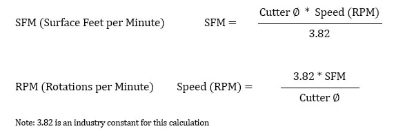
Surface Foot is based on the various properties of the given material. Speed, referred to as Rotations Per Minute (RPM) is based off of the SFM and the cutting tool’s diameter. As SFM is tied to the properties of a material, it does not change based upon the operation being performed and remains constant despite changes in chip load calculation.
How Do You Calculate Surface Feet per Minute (SFM)?
The SFM calculation utilizes the industry standard of 3.82. Here, the cutter diameter of the chosen tool is multiplied by the speed or RPM. This figure is then divided by 3.82 to generate the SFM or Surface Feet per Minute.
Feed Rate and Chip Load Calculations
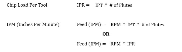
While speeds and feeds are common terms used in the programming of the cutter, the ideal running parameters are also influenced by a myriad of other variables. As speeds and feeds must be well-matched to be effective, the speed of the cutter is used in the calculation of the cutter’s feed rate, measured in Inches Per Minute (IPM).
The other part of the equation is the chip load, or material being removed per revolution. It is important to note that chip load per tooth and chip load per tool are different:
Chip load per tooth is the appropriate amount of material that one cutting edge of the tool should remove in a single revolution. This is measured in Inches Per Tooth (IPT).
Chip load per tool is the appropriate amount of material removed by all cutting edges on a tool in a single revolution. This is measured in Inches Per Revolution (IPR).
A chip load that is too large can pack up chips in the cutter, causing poor chip evacuation and eventual breakage. A chip load that is too small can cause rubbing, chatter, tool deflection, and a poor overall cutting action. Finding the correct balance will not only allow for the most efficient cut possible, but also ensures the most efficiency in regard to tool wear. When calculating chip load per tool or IPR, the per tooth chip load is aptly multiplied by the number of flutes on the tool itself.
Material Removal Rate
Material Removal Rate (MRR), while not part of the cutting tool’s program, is a helpful way to calculate a tool’s efficiency. MRR takes into account two very important running parameters: Axial Depth of Cut (ADOC), or the distance a tool engages a workpiece along its centerline, and Radial Depth of Cut (RDOC), or the distance a tool is stepping over into a workpiece.
The MRR calculation (seen below) relies on the calculated feed rate. The feed rate (IPM) is multiplied by the radial and axial depths of cut to produce the rate of removal.
The tool’s depth of cuts and the rate at which it is cutting can be used to calculate how many cubic inches per minute (in3/min) are being removed from a workpiece. This equation is extremely useful for comparing cutting tools and examining how cycle times can be improved. Decreased cycle times leads to higher productivity within a shop, which is what all machinists aim for during production.
Adjusting depths of cut can decrease time in cut and overall production time, freeing up machines for additional manufacturing. An example of depth of cut adjustment is seen in High Efficiency Milling, where RDOC is decreased and ADOC is increased. In this method, MRR is increased while also reducing tool wear, leading to higher productivity and more parts per tool.
Speeds and Feeds In Practice
While many of the cutting parameters are set by the tool and workpiece material, the depths of cut taken also affect the feed rate of the tool. The depths of cuts are dictated by the operation being performed – this is often broken down into slotting, roughing, and finishing. Though there are many other more specific types of operations.
These unique operations utilize much different depths of cut, with industry standardized terms as description. Slotting can be described as utilizing 180° of the diameter of the tool engaged in the cut.
Roughing on the other hand will typically disperse both ADOC and RDOC relatively evenly. Finally, finishing operations will use substantially more axial depths of cut in relation to radial, leaving the best finish possible on the workpiece.
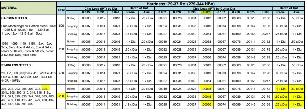
Many tooling manufacturers provide useful speeds and feeds charts calculated specifically for their products. For example, Harvey Tool provides the following chart for a 1/8” diameter end mill, tool #50308.
A customer can find the SFM for the material on the left, in this case 304 stainless steel (highlighted in yellow). The chip load (per tooth) can be found by intersecting the tool diameter on the top (blue heading) with the material and operations (based on axial and radial depth of cut), highlighted in the image below.
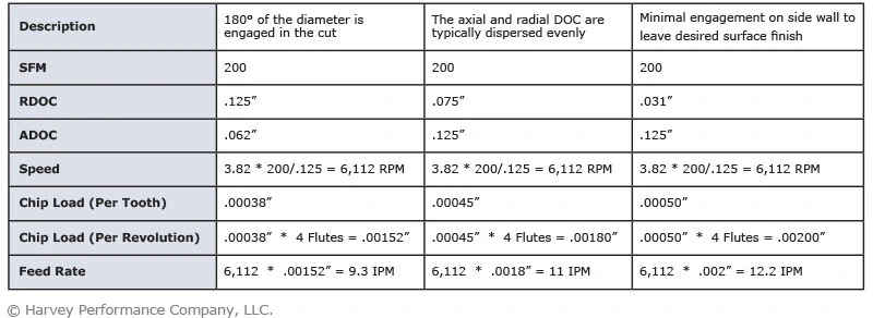
The following table calculates the speeds and feeds for this tool (#50308) and material (304 Stainless) for each operation, based on the chart above:
Each operation recommends a unique chip load per the depths of cut depending on the operation, thus resulting in different feed rates for the desired application. Since the SFM is based on the material, it will always remain constant for each of the three defined operations.
Milling speeds between materials vary drastically. For example, the milling speed for stainless will differ than that of much softer aluminum. Therefore, it is always important to factor in materials when examining speeds and feeds chart and performing calculations.
Spindle Speed Cap
As shown above, the cutter speed (RPM) is defined by the SFM (based on material) and the cutter diameter. With miniature tooling and/or certain materials the speed calculation sometimes yields an unrealistic spindle speed.
For example, a .047” cutter in 6061 aluminum (SFM 1,000) would return a speed of ~81,000 RPM. Since this speed is only attainable with high speed air spindles, the full SFM of 1,000 may not be achievable. In a case like this, it is recommended that the tool is run at the machine’s max speed (that the machinist is comfortable with) and that the appropriate chip load for the diameter is maintained. This produces optimal parameters based on the machine’s top speed.
All machines are unique and provide different max speed, therefore these calculations will vary based on machine capabilities within your shop.
Effective Cutter Diameter
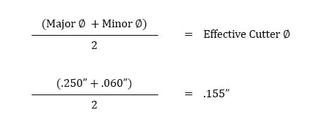
On angled tools the cutter diameter changes along the LOC. For example, Helical tool #07001, a flat-ended chamfer cutter with helical flutes, has a tip diameter of .060” and a major/shank diameter of .250”. In a scenario where it was being used to create a 60° edge break, the actual cutting action would happen somewhere between the tip and major/shank diameters. To compensate, the equation below can be used to find the average diameter along the chamfer.
Using this calculation, the effective cutter diameter is .155”, which would be used for all Speeds and Feeds calculations.
Non-linear Path
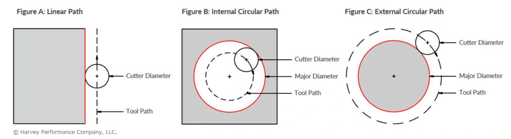
Feed rates assume a linear motion. However, there are cases in which the path takes an arc, such as in a pocket corner or a circular interpolation. Just as increasing the DOC increases the angle of engagement on a tool, so does taking a nonlinear path. For an internal corner, more of the tool is engaged and, for an external corner, less is engaged. The feed rate must be appropriately compensated for the added or lessened engagement on the tool to provide the most effective and desired IPM for the chosen application.
In the below graphic, Figure A is showcasing a linear path on a part, with a standard engagement. Figure’s B and C demonstrate the increase and decrease of engagement in non-linear, circular toolpaths. Utilizing identical feed rates between the three paths would generate three wildly different IPMs despite similar setups.
This adjustment is even more important for circular interpolation. Take, for example, a threading application involving a cutter making a circular motion about a pre-drilled hole or boss. For internal adjustment, the feed rate must be lowered to account for the additional engagement. For external adjustment, the feed rate must be increased due to less tool engagement.
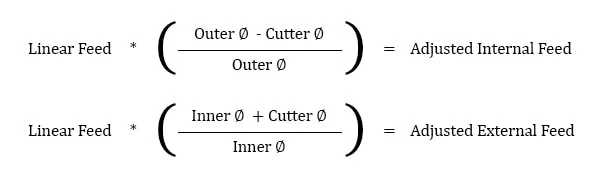
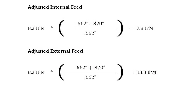
An adjustment in internal feed subtracts the differences in cutter diameters from the differences in outer diameters before dividing by the outer dia. difference. On the other hand, adjusting for external feed adds the differences between cutter diameters to the differences in inner diameters before dividing by the inner dia. difference.
Take this example, in which a Harvey Tool threadmill #70094, with a .370” cutter diameter, is machining a 9/16-18 internal thread in 17-4 stainless steel. The calculated speed is 2,064 RPM and the linear feed is 8.3 IPM. The thread diameter of a 9/16 thread is .562”, which is used for the inner and outer diameter in both adjustments. After plugging these values into the equations below, the adjusted internal feed becomes 2.8 IMP, while the external feed becomes 13.8 IPM.
SFM in Conclusion
These calculations are useful guidelines for running a cutting tool optimally in various applications and materials. However, the tool manufacturer’s recommended parameters are the best place to start for initial numbers and to set a baseline for the best tool performance.
After that, it is up to the machinist’s eyes, ears, and experience to help determine the best running parameters, which will vary by set-up, tool, machine, and chosen material. No operation is exactly the same, and nothing occurs in a vacuum. Experience and continued learning will always aid machinists in ensuring the most efficient performance possible in the cut.
The following links have the most up to date information on running parameters for Harvey Tool, Helical, Titan USA, and CoreHog CNC products.
https://www.harveyperformance.com/wp-content/uploads/2017/10/Feature-Image-Speeds-Feeds-IMG.jpg5251400Harvey Performance Companyhttp://www.harveyperformance.com/wp-content/uploads/2018/08/Logo_HarveyPerformanceCompany-4.pngHarvey Performance Company2017-10-02 17:00:172025-02-14 10:48:58Speeds and Feeds 101
One of the most important considerations when choosing an end mill is determining which flute count is best for the job at hand. Both material and application play an important role in this critical part of the tool selection process. Understanding the effects of flute count on other tool properties, and how a tool will behave in different situations is an essential consideration in the tool selection process. As end mills have become more and more advanced, certain standards have been created for flute counts in certain materials. While there is obvious overlap due to a myriad of factors, proper flute count is critical for machining success and ensuring you are making the most of your end mill and it’s associated MRR.
Machining Advisor Pro (MAP) Takes Flute Count Into Consideration When Helping You Dial In Running Parameters.
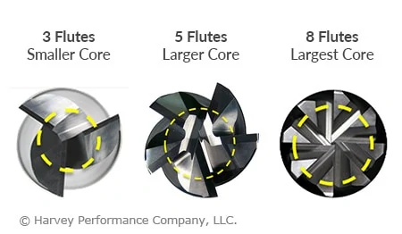
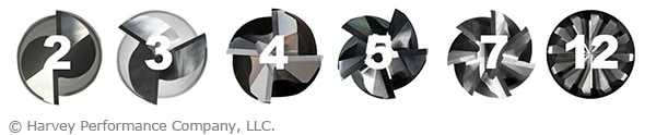
Generally, tools with more flutes have a larger core and smaller flute valleys than tools with fewer flutes. More flutes with a larger core can provide both benefits and restrictions depending on the application. Simply put, a larger core is directly proportional to tool strength; the larger the core, the stronger a tool will be. In turn, a larger core also reduces the flute depth of a tool, restricting the amount of space for chips to exist. This can cause issues with chip packing in applications requiring heavy material removal. However, these considerations only lead us part way when making a decision on which tool to use, and when.
Material Considerations
Traditionally, end mills came in either a 2 flute or 4 flute option. The widely accepted rule of thumb was to use 2 flutes for machining aluminum and non-ferrous materials, and 4 flutes for machining steel and harder alloys. As aluminum and non-ferrous alloys are typically much softer than steels, a tool’s strength is less of a concern, a tool can be fed faster, and larger material removal rates (MRR) is facilitated by the large flute valleys of 2 flute tools.
Consequently, ferrous materials are typically much harder, and require the strength of a larger core. Feed rates are slower, resulting in smaller chips, and allowing for the smaller flute valleys of a larger core tool. This also allows for more flutes to fit on the tool, which in turn increases productivity.
Recently, with more advanced machines and toolpaths, higher flute count tools have become the norm in manufacturing. Non-ferrous tooling has become largely centered on 3 flute tools. This has created a slight advantage over 2 flute tools by increasing productivity while still affording proper chip evacuation. The softness of non-ferrous materials affords a much deeper flute valley. As previously discussed, this allows the tool to be fed much faster than in ferrous materials. Adding an additional flute increases the productivity of the tool, while still affording machinists faster feed rates.
Ferrous tooling has taken a step further and progressed not only to 5 and 6 flutes, but up to 7 flutes and more in some cases. With a wider range of hardness, sometimes at the very top of the Rockwell hardness scale, many more flutes have allowed longer tool life, less tool wear, stronger tools, and less deflection. All of this results in more specialized tools for more specific materials. Material specific tooling combines proper flute counts with coatings that aid in lubricity and heat generation to ensure the most effective end mill possible in the material being machined. The end result is higher MRR and increased productivity across the entire range of ferrous materials that machinists will work with in their shops.
Running Parameters
Just as material considerations will have an impact on the tool you choose, operation type and depth of cut requirements may also have a big impact on the ideal number of flutes for your application. In roughing applications, lower flute counts may be desirable to evacuate large amounts of chips faster with larger flute valleys. That said, there is a balance to find, as modern toolpaths such as High Efficiency Milling (HEM) can achieve extreme MRR with a very small step over, and a higher number of flutes. In a more traditional sense, higher flute counts are great for finishing operations where very small amounts of material are being removed, and greater finish can be achieved with more flutes, not worrying as much about chip evacuation as that phase has already been accomplished during roughing.
Flute count plays a big role in speeds and feeds calculation as well. One common rule of thumb is “more flutes, more feed,” but this can be a very detrimental misconception. Although true in some cases, this is not an infinitely scalable principle. As stated previously, increasing the number of flutes on a tool limits the size that the flute valleys can be. While adding a 5th flute to a 4 flute tool theoretically gives you 25% more material removal per revolution with an appropriately increased feed rate, feeding the tool that much faster may overload the tool. The 25% increase in material removal is more likely closer to 10-15%, given the tool is exactly the same in all other specifications. Higher flute count tools may require speeds and feeds to be backed off so much in some cases, that a lower flute count may be even more efficient. Finding the right balance is key in modern milling practices. Consulting a tooling manufacturer’s speeds and feeds will be the perfect starting point, and then machinists can make changes as they see fit to properly accomplish the job at hand.
In all, the importance of flute count identification is critical to continued success at the spindle. Different materials have different strength requirements as well as variability in how much material can be appropriately removed per tooth.
Composites are a group of materials made up of at least two unique constituents that, when combined, produce mechanical and physical properties favorable for a wide array of applications. These materials usually contain a binding ingredient, known as a matrix, filled with particles or fibers called reinforcements. Composites have become increasingly popular in the Aerospace, Automotive, and Sporting Goods industries because they can combine the strength of metal, the light weight of plastic, and the rigidity of ceramics.
Unfortunately, composite materials present some unique challenges to machinists. Many composites are very abrasive and can severely reduce tool life, while others can melt and burn if heat generation is not properly controlled. Even if these potential problems are avoided, the wrong tool can leave the part with other quality issues, including delamination.
While composites such as G10 and FR4 are considered “fibrous”, composites can also be “layered,” such as laminated sheets of PEEK and aluminum. Layered composites are vulnerable to delamination, when the layers of the material are separated by a tool’s cutting forces. This yields less structurally sound parts, defeating the purpose of the combined material properties in the first place. In many cases, a single delaminated hole can result in a scrapped part.
Using Compression Cutter End Mills in Composite Materials
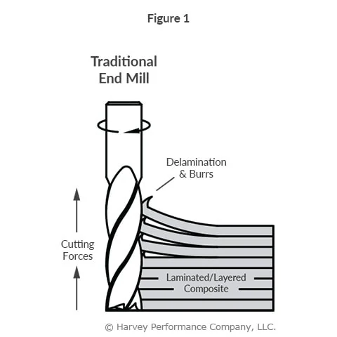
Composite materials are generally machined with standard metal cutting end mills, which generate exclusively up or down cutting forces, depending on if they have right or left hand flute geometry. These uni-directional forces cause delamination (Figure 1).
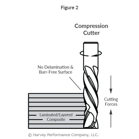
Conversely, compression cutters are designed with both up and down-cut flutes. The top portion of the length of cut, closest to the shank, has a left hand spiral, forcing chips down. The bottom portion of the length of cut, closest to the end, has a right hand spiral, forcing chips up. When cutting, the opposing flute directions generate counteracting up-cut and down-cut forces. The opposing cutting forces stabilize the material removal, which compresses the composite layers, combatting delamination on the top and bottom of a workpiece (Figure 2).
Since compression cutters do not pull up or press down on a workpiece, they leave an excellent finish on layered composites and lightweight materials like plywood. It is important to note, however, that compression cutters are suited specifically to profiling, as the benefits of the up and down-cut geometry are not utilized in slotting or plunging operations.
Something as simple as choosing a tool suited to a specific composite material can have significant effects on the quality of the final part. Consider utilizing tools optimized for different composites and operations or learn how to select the right drill for composite holemaking.