
3 Steps to Shutting up Tool Chatter
What is Chatter in Machining?
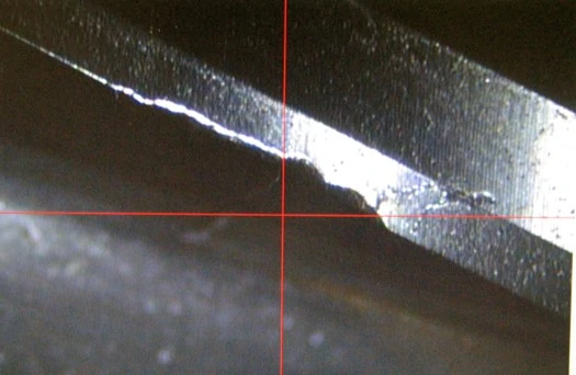
Cutting tools undergo a great deal of force during the machining process, which cause vibrations – also known as chatter or harmonics. Avoiding these vibrations entirely is not possible, though minimizing them is pivotal for machining success. Vibrations become damaging when proper machining steps are not followed. This leads to strong, part-ruining chatter. In these situations, parts have what is known as “chatter marks,” or clear vibration marks along the surface of a part. Tools can experience an increased rate of wear due to excess vibration.
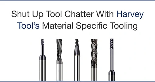
Shut Up Tool Chatter With Harvey Tool’s Material Specific Tooling
How to Reduce Chatter in Machining
Select the Right Tool for Your Job
It seems elementary, but selecting the best tool for your application can be confusing. With so many different geometric styles for tooling – overall length, length of cut, reach, number of flutes – it can sometimes be difficult to narrow down one specific tool for your job. Oftentimes, machinists opt for general purpose tooling that can perform a variety of operations, overlooking the option that’s optimized for one material and job.
Use Material Specific Tooling
Opting for Material Specific Tooling is helpful, as each material has different needs. For example, steels are machined differently than aluminum materials. Everything from the chip size, to chip evacuation, is different. Variable Helix or Variable Pitch designs help to minimize chatter by reducing harmonics, which are caused by the cutting edge having repeated contact with the workpiece. In order to reduce harmonics, the time intervals between flute contact with the workpiece are varied.
Consider Tool Length
Overall length is another important factor to consider when deciding on a tool for your job. The more overhang, or length the tool hangs from the spindle, the less secure the spindle-to-tool connection is, and the more vibration. Ensuring that your tool is only as long as needed for your operation is important to minimizing chatter and harmonics. If machining deep within a part, opt for reached tooling or an extended reach tool holder to help solidify the connection.
Ensure a Secure Connection
Tool Holder & Shank Relationship
When it comes to secure tool holding approaches, both the tool shank and the collet are important. A loose tool, unsurprisingly, has more ability to move, or vibrate, during machining. With this in mind, Helical offers Shank Configurations to help the connection including the ToughGRIP Shank, which replaces a smooth, mirror-like surface with a rougher, coarser one for increased friction. Helical is also a licensee of the HAIMER Safe-Lock™, added grooves on the shank of a tool that work opposite of the spindle rotation, securely fastening the tool in place.

Choosing Collet Types
Machinists must also know the different types of collets available to them to identify if a better solution might be necessary. For example, Hydraulic Tool Holders or Shrink Fit Tool Holders promote a stronger connection than a Mechanical Spindle Tightening method.
For more information, see Key Tool Holding Considerations
Selecting a Chatter Minimizing Strategy
How a tool is run can mean the difference between stellar job results and a ruined part. This includes both the parameters a tool is run at, as well as the direction by which it rotates – either a Conventional Milling or a Climb Milling technique. The key distinction between these two methods lies in the relationship between the cutter’s rotation and the direction of the feed.
Conventional Milling
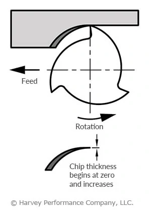
In conventional milling, the chip width starts from zero and increases gradually, causing the process of heat generation onto the workpiece rather than the chips. Heat generation causes deformities and tool failure such as work hardening, creating more headaches for a machinist. For this reason, conventional milling is generally only recommended for tools with high toughness or for breaking into case hardened materials.
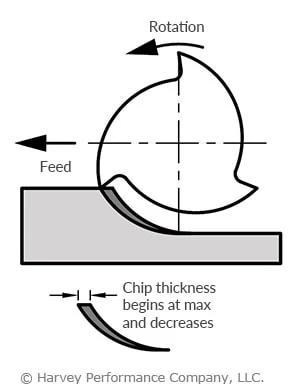
Climb Milling
Most modern machine shops will use a climb milling technique, or when the chip width starts at its maximum and decreases during the cut. Climb Milling will offer a more consistent cut than traditional methods, and puts less stress on the tool. Think of it like weight lifting – doing the heavy lifting will be easiest at the beginning of your workout. Similarly, a cut in which the thickest chip is removed first helps the tool maintain its strength. Because the chip cutting process is more swift, vibrations are minimized.
For more information, see Climb Milling Vs. Conventional Milling
In Conclusion
Vibrations are unavoidable during the machining process, but minimizing them can mean the difference between successful machining and scrapped parts. Following three simple rules can help to keep your chatter and harmonics under control, including: Selecting the right tool, ensuring a secure machine-tool connection, and using it in a climb milling strategy. Both Harvey Tool and Helical Solutions have tools that can help, including shank modifications and Variable Helix or Variable Pitch end mills.


Your conventional and climb cutting illustrations appear to be viewed from the “bottom” looking up at the spindle, which is confusing. It would be better understood to view this from the operator’s perspective, which is looking down at the workpiece and showing the cutter rotation from that view.
THIS CAN BE VIEWED TOP OR BOTTOM. IT IS CORRECT BOTH WAYS YOU LOOK AT IT…
i agree with Leon D.
if you looking top down, then its a left hand cutter
I agree with Leon, I am always perplexed as to why cutting tool manufacturers depict climb and conventional milling in this fashion.
We certainly see where you’re coming from with the images. Showing them from a machinist’s POV would likely convey a clearer message. We’ll shoot to make these updated images for future posts!
What if you are using left handed tools? Seems like a very minor thing
Thanks Jeff-it has bothered me for a long time as well. From my POV, typically you are looking down on the spindle which has a CW rotation, and I can ‘flip’ it in my mind, but it is WAY easier to visualize by what I ‘normally’ see, from above with a CW rotation.
Nice article. Thanks
You also need to check for toolholder expansion caused by the retention knob. Regardless of the choice of tool, if the holder and the spindle don’t make full contact at the gage line, you’ll be fighting a losing battle.
I find the comments on the view from the bottom interesting. The picture shows the intended result, chip formation. I wonder if these guys have trouble visualizing blueprints in 3D space in their mind. I started on a drawing board in high school and now use SolidWorks. In short that made me able to visualize in 3D parts in my head from blueprints. Today’s schools skip right to 3D modeling which, I think we are creating engineering students that do not have all the skills they need. Its kind of like programming a CNC with out ever cutting a chip on a manual machine, you have no idea what you are doing except what cutting parameters came from a book. It makes it hard to trouble shoot any problem that may occur, and we all know that happens regularly.
100% agree with you on this. I started “hands on” making chips then moved into the 2D drafting then moved to the 3D cad world. The old school 2D guys have difficulty seeing the 3D and the new kids on the block have difficulty interpreting the 2D stuff.
agree with you guys. those crying about the standard pictured view of milling directions since the 1800s, have more troubles then just chatter.
I absolutely love your comment. I started on manual machines, and because I knew enough about how to do machining was able to teach myself to run a CNC first by hand writing code and later in a CAM program. After that I was ready to teach myself Autocad 2d and 3d, and then Autodesk Inventor.
Hey love the article, but in my opinion your missing a crucial #4 in reducing chatter and that is leaving consistent stock on the walls and any contours To ensure proper cutter engagement.
Thank you both for the comments! We certainly agree that there are several ways to mitigate chatter that aren’t mentioned in this article, and both of your suggestions are valid!
Article doesn’t mention depth of cut or rpm change. A small depth of cut will get rid of chatter. Occasionally changing the rpm will get rid of the chatter. Another thing is a roughing mill.
I like what you said about making sure that you’re using the right tool to cut down on noise when using machinery. My boss has been telling me about some things that he wants to get built soon, and he wants to make sure that the shop doesn’t get too loud while this happens. I’ll share this information with him so that he can be sure to pick the right machines for the job.
Why is Harvey blocking my posts? Nothing controversial about what I said. Keep doing this and see if I ever buy your cutters again.
Hi Jimbo – we are not blocking comments. All comments go into a review hold so that we can weed out the spam comments. As you can imagine, we do get quite a few.
We certainly appreciate your comments and conversation on this post and others and have approved all of your previous comments as well!
HI! Could you do an article on resolving chatter for lathes and stick tools?
Thanks,
Frank
Hey Frank, thank you for the suggestion! We can try to work on that article.
I like that this post mentioned that it is important for us to know the right tools to use when undertaking any project. The other day my sister mentioned that her husband is planning to build his own garage. I will advise him to use the proper tools before taking on such a task.
That is some funny stuff. This article is definitely made for beginner programmers. On the long LBS cutters, I suggest lowering surface footage and maintaining a heavy chip load. A lot of guys tend to reduce the feed too much. This isn’t helping and is increasing run time significantly.
The illustration is fine, I would encourage operators to take enough time to fully understand the concept of the illustration rather than dismissing it as invalid from their stand point. The focus is on what the cutter is doing and the nomenclature describing the operation. yet, conventional passes have a valid use in machining processes.
One that I found is when machining the edges of plasma cut material, especially when it was quenched for handling purposes.
Perhaps left hand tooling was used…..lol. The pictures are not confusing in any way,shape, or form to me.