Your Guide to Thin Wall Milling

Milling part features with thin wall characteristics, while also maintaining dimensional accuracy and straightness, can be difficult at best. Although multiple factors contribute, some key components are discussed below and can help to increase your thin wall milling accuracy.

Use Proper Tooling

Necked Tooling

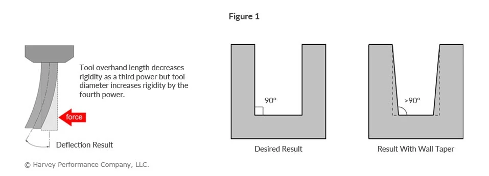
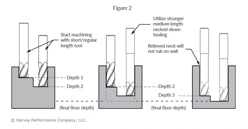
Long length tooling with a long length of cut can spell trouble in thin wall milling situations due to deflection, chatter and breakage. It is essential to keep your tool as strong as possible while maintaining the ability to reach to the desired depth. Necked-down tooling provides added tool strength while also helping you to reach greater than 3x Diameter depths.

image comparing end mills with and without a reduced neck

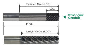
The total extension of an end mill, referred to as length below shank (LBS), represents the dimension that characterizes the necked length of the tool in use. This measurement is taken from the beginning of the necked section to the bottom of the cutting end of the tool. The neck relief serves the purpose of creating room for chip removal and preventing the shank from friction in deep-pocket milling scenarios.

Depth of Cut Selection

Axial Depth of Cut (ADOC)

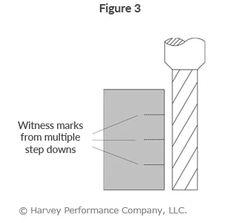
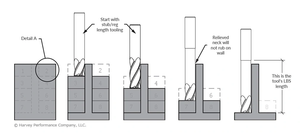
To support the walls during thin wall machining, keep a wide-cross section behind it. We recommend utilizing a “stepped down” approach, which divides the total wall height to manageable depths while working each side of the wall. The Axial Depth of Cut (ADOC) dimension will vary depending on the material (and its hardness) being cut.

Chart of proper ADOC in thin wall milling

Radial Depth of Cut (RDOC)

A progressive Radial Depth Of Cut (RDOC) strategy is also important as the thin wall height is increasing. Reducing tool pressure while support stock is disappearing is equally important to keep the thin wall stable.

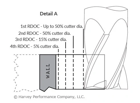
  • Detail A represents a 5-step progressive radial approach. The number of passes will depend upon your particular application, material hardness and final wall dimensions.
  • This approach helps to keep the pressure off the wall as you make your way towards it. Additionally, it is recommended to alternate sides when using this RDOC strategy.
  • The final RDOC passes should be very light to keep wall vibration to a minimum while maximizing your part finish.

RDOC steps in thin wall milling

Additional Thin Wall Milling Accuracy Tips:
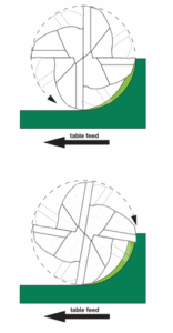
Climb Milling

Climb milling, gaining popularity among machinists seeking efficiency and extended tool life, minimizes heat generation and friction. Chips are ejected behind the cutter, reducing the likelihood of chip recutting. The chip initiates at its widest point and diminishes, leading to the transfer of generated heat into the chip rather than the tool or workpiece. This results in longer tool lifespan, enabling more parts per tool and lessened costs. Additionally, it contributes to a superior part finish by optimizing chip formation at the cutting edge.

drawing demonstrating the difference between conventional and climb milling with the direction of an end mill

Wall Stabilization

Manual vibration dampening and wall stabilization can be achieved by using thermoplastic compounds, or wax, which can be thermally removed.

HEM Toolpaths

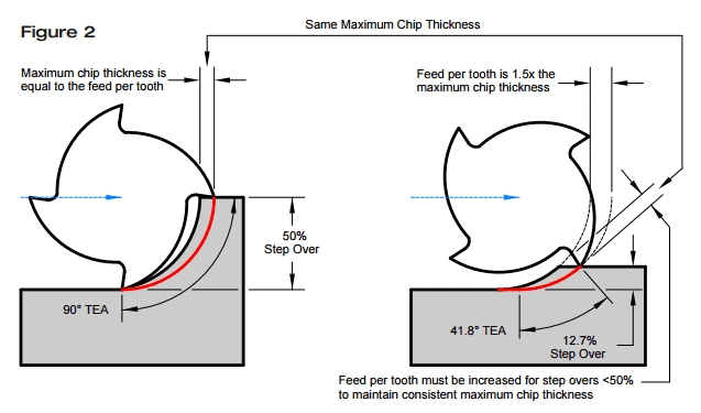
The use of HEM toolpaths can optimize tool performance. It is an advanced machining approach which involves combining a low RDOC (Radial Depth of Cut) with a high ADOC (Axial Depth of Cut), along with elevated feed rates. This combination aims to enhance material removal rates and reduce tool wear.

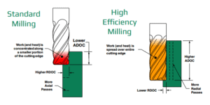
High Efficiency Milling (HEM) varies from conventional milling, where a higher RDOC and lower ADOC are usually recommended. Conventional milling tends to generate concentrated heat in a specific area of the cutting tool, expediting tool wear. Additionally, while conventional milling requires more axial passes, HEM toolpaths involve more radial passes.

How to Tackle Deep Cavity Milling the Right Way

Deep cavity milling is a common yet demanding milling operation. In this style, the tool has a large amount of overhang – or how far a cutting tool is sticking out from its tool holder. The most common challenges of deep cavity milling include tool deflection, chip evacuation, and tool reach.

Three Harvey tool extended reach tool holders in 3, 5, and 6 inch lengths

Avoid Tool Deflection

Excess overhang is the leading cause of tool deflection, due to a lack of rigidity. Besides immediate tool breakage and potential part scrapping, excessive overhang can compromise dimensional accuracy and prevent a desirable finish.

Tool deflection causes wall taper to occur (Figure 1), resulting in unintended dimensions and, most likely, an unusable part. By using the largest possible diameter, necked tooling, and progressively stepping down with lighter Axial Depths Of Cut (ADOC), wall taper is greatly reduced (Figure 2).

Infographic showing result of tool deflection and excess overhang on a part's finish
Infographic showing progressive step drilling procedures and depths of cut with varied length of tools

Achieve Optimal Finish

Although increasing your step-downs and decreasing your ADOC are ideal for roughing in deep cavities, this process oftentimes leaves witness marks at each step down. In order to achieve a quality finish, Long Reach, Long Flute Finishing End Mills (coupled with a light Radial Depth of Cut) are required (Figure 3).

Inforgraphic showing Deep Cavity Milling and witness marks from multiple step downs

Mill to the Required Depth

Avoiding tool deflection and achieving an acceptable finish are challenges that need to be acknowledged, but what if you can’t even reach your required depth? Inability to reach the required depth can be a result of the wrong tool holder or simply a problem of not having access to long enough tooling.

Fortunately, your tool holder’s effective reach can be easily increased with Harvey Tool’s Extended Reach Tool Holder, which allows you to reach up to 6 inches deeper.

Confidently Machine Deeper With Harvey Tool’s Extended Reach Tool Holders

Evacuate Chips Effectively

Many machining operations are challenged by chip evacuation, but none more so than Deep Cavity Milling. With a deep cavity, chips face more obstruction, making it more difficult to evacuate them. This frequently results in greater tool wear from chip cutting and halted production from clogged flute valleys.

High pressure coolant, especially through the spindle, aids in the chip evacuation process. However, air coolant is a better option if heat and lubricity are not concerns, since coolant-chip mixtures can form a “slurry” at the bottom of deep cavities (Figure 4). When machining hardened alloys, where smaller, powder-like chips are created, slurry’s are a commonality
that must be avoided.

Deep Cavity Milling image showing result of failed chip evacuation when milling

How to Combat Chip Thinning

The following is just one of several blog posts relevant to High Efficiency Milling. To achieve a full understanding of this popular machining method, view any of the additional HEM posts below!

Introduction to High Efficiency Milling I High Speed Machining vs. HEM I Diving into Depth of Cut I How to Avoid 4 Major Types of Tool Wear I Intro to Trochoidal Milling


Defining Chip Thinning

Chip Thinning is a phenomenon that occurs with varying Radial Depths Of Cut (RDOC), and relates to chip thickness and feed per tooth. While these two values are often mistaken as the same, they are separate variables that have a direct impact on each other.

cnc machining setup covered in chips

Radial Depth of Cut

Radial Depth of Cut denotes the distance that a tool advances into a workpiece, also known as Stepover, Cut Width, or XY.

Feed Per Tooth

Feed per tooth translates directly to your tool feed rate, and is commonly referred to as Inches Per Tooth (IPT) or chip load.

Chip Thickness

Chip thickness is often overlooked. It refers to the actual thickness of each chip cut by a tool, measured at its largest cross-section. Users should be careful not to confuse chip thickness and feed per tooth, as these are each directly related to the ideal cutting conditions.

Download the Free, 50+ Page High Efficiency Milling Guidebook Today

How Chip Thinning Occurs

When using a 50% step over (left side of Figure 1), the chip thickness and feed per tooth are equal to each other. Each tooth will engage the workpiece at a right angle, allowing for the most effective cutting action, and avoiding rubbing as much as possible. Once the RDOC falls below 50% of the cutter diameter (right side of Figure 1), the maximum chip thickness decreases, in turn changing the ideal cutting conditions of the application. This can lead to poor part finish, inefficient cycle times, and premature tool wear. Properly adjusting the running parameters can greatly help reduce these issues.

comparison of radial chip thinning and feed per tooth

The aim is to achieve a constant chip thickness by adjusting the feed rate when cutting at different RDOC. This can be done with the following equation using the Tool Diameter (D), RDOC, Chip Thickness (CT), and Feed Rate (IPT). For chip thickness, use the recommended value of IPT at 50% step over. Finding an adjusted feed rate is as simple as plugging in the desired values and solving for IPT. This keeps the chip thickness constant at different depths of cut. The adjustment is illustrated in Figure 2.

Inches Per Tooth (Chip Thinning Adjustment)

IPT chip thinning formula
radial chip thinning adjustment profiles

Lasting Benefits

In summary, the purpose of these chip thinning adjustments is to get the most out of your tool. Keeping the chip thickness constant ensures that a tool is doing as much work as it can within any given cut. Other benefits include: reduced rubbing, increased material removal rates, and improved tool life.

High efficiency milling guidebook download