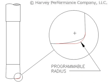
Corner Comparison: Corner Chamfer vs. Corner Radius
Using Finite Element Analysis (FEA) simulations by Third Wave Systems’ AdvantEdge CAE product, we tested different end mill corner geometries to compare their effects on both the tool and the workpiece. We studied and compared four 4 flute tools with either a 0.010” or 0.030” radius or chamfer. All tools were tested in 304 stainless steel at 1865 RPM, 244 SFM, and 0.0045 IPT for one revolution.
Both Corner Radius and Corner Chamfer tools offer advantages over Square End Mills by improving tool strength and reducing wear, though their benefits vary. One drawback of corner radius end mills is chip thinning along the radius, which can generate excess heat due to changes in chip thickness. This can lead to premature tool wear, poor surface finish, and potential work hardening. On the other hand, Corner Chamfers have the disadvantage of sharp corners where the chamfer meets the outer diameter (OD) and the end of the tool, causing local stress concentrations.
Force Analysis
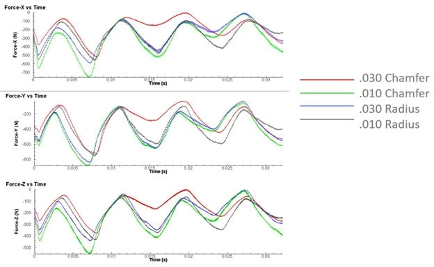
The graphs above demonstrate the force exerted on the tool during cutting and how the corner size impacts the required force. As each flute engages, the forces peak in each direction. The 0.010” Chamfer generates the greatest force, while the 0.030” Chamfer requires the least. The forces with the radiused tools are very similar and fall between those of the two chamfered tools.
Temperature Analysis
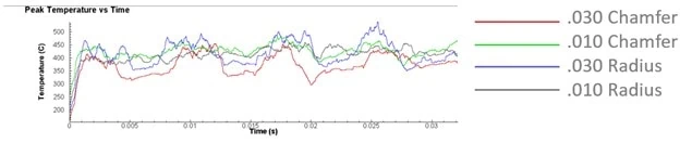
The peak tool temperature graph shows the impact of chip thinning on corner radius tools and the overall corner size. The 0.030” Radius generated the most heat, while the 0.030” Chamfer generated the least. The temperature differences between the 0.010” Chamfer and 0.010” Radius was minimal, with the 0.010” Radius generated slightly less heat.
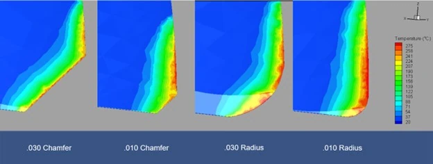
Chip and Workpiece Temperature
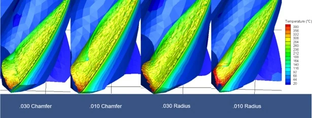
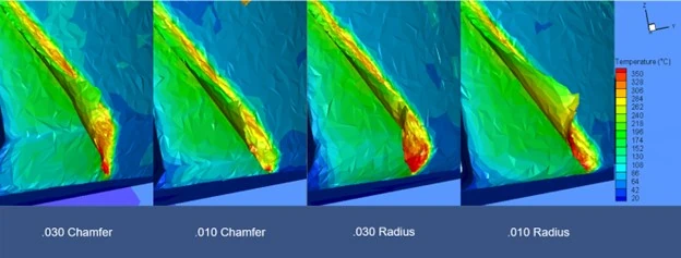
Understanding the temperature of the chip and workpiece is crucial for assessing tool performance. The contours above illustrate that the most heat is generated along the 0.030” Radius, followed by the 0.010” Radius. Corner Chamfer tools performed better, maintaining a lower overall temperature due to the absence of chip thinning.
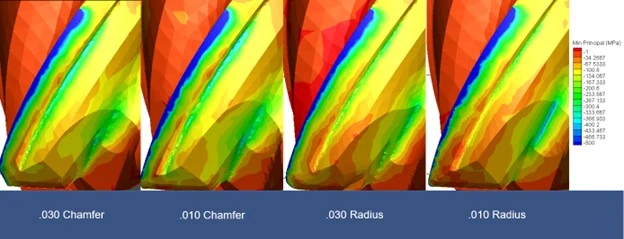
Stress Analysis
The minimum principal stress on the backside of the flute indicates areas prone to tool failure. While there were slight differences between the chamfers and radii, the most notable finding was the reduction in stress with increased corner break size.
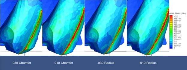
Similarly, the Mises stress analysis shows where stress is concentrated within the tool, potentially leading to failure. Again, the most significant observation was the reduction in stress with larger corner breaks.
Corner Chamfer vs. Corner Radius: Wrapped Up
Considering all factors, the 0.030” Corner Chamfer proved to be the best overall tool for 304 stainless steel. This is partly due to 304’s tendency to work harden, making excess heat generation particularly detrimental. When working with heat-sensitive materials, Corner Chamfer tools are preferable, especially during roughing, as they generate less heat due to the absence of chip thinning. Although there are minor stress concentrations at the sharp corners of Corner Chamfer tools, these are outweighed by the benefits of reduced heat generation. Larger radii exacerbate chip thinning’s impact on heat generation. While both tool styles offer advantages over square end mills, Corner Chamfer tools are more beneficial in high-heat applications where work hardening and tool wear are concerns.
Harvey Tool offers a range of Corner Chamfer Tools, with sizes ranging from 0.047” to 0.500” and various chamfer sizes to suit different applications.