Mastering CNC Drilling: Exploring Geometries and Key Factors
Selecting the proper CNC drill for a specific application is essential to ensuring a successful job, but achieving a perfectly machined hole can be challenging. There are many machining woes that can occur when drilling into a material, which can greatly affect hole quality, and regardless of the material being machined, there is often zero margin for error to ensure all components meet specifications.
To ensure you are selecting and using the correct drill, you need not only a deep understanding of drill geometries, but also the factors that influence the performance of the drill and quality of the hole. In this comprehensive guide, we’ll dive into drill geometries, while also exploring the performance factors that determine CNC drilling results. Furthermore, we’ll connect these aspects to the strategic decisions that drive the tool selection process, so you can gain a competitive edge at the spindle.
Performance Factors Influencing CNC Drill Success
Part Material
Different materials require different drill geometries and cutting speeds to maintain hole quality and prevent excessive wear. With different types of materials, whether it be a softer non-ferrous material like Aluminum or a harder, ferrous material like Stainless Steels, you’ll face different challenges as you manufacture your part. To ensure that you’re getting the best performance and tool life possible regardless of your material, the following features & geometries are considered.
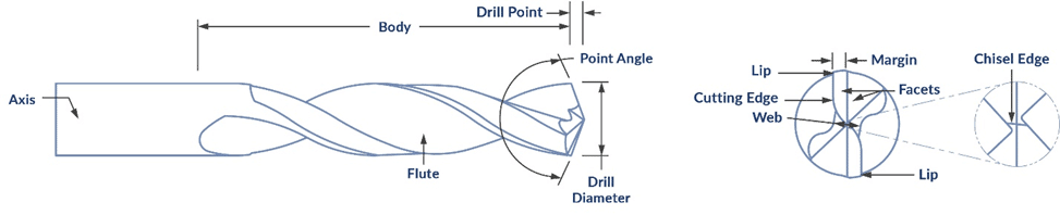
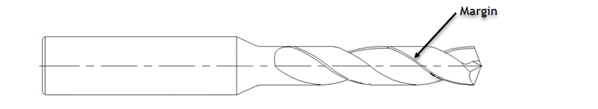
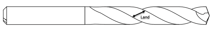
CNC Drill Geometries
It is important to understand the different geometries of a drill to understand how they affect an application and which you should be looking for when selecting your next tool. For an in depth dive into drill geometries, read 10 CNC Drill Geometries Every Machinist Must Know.
CNC Drill Geometries and Drill Walking
CNC drill walking occurs when a CNC drill lacks sufficient engagement with the material, causing it to deviate from its intended tool path, leading to inaccuracies in hole placement and dimensions. This can occur due to various factors, including improper drill geometry. Understanding how different drill geometries influence drill walking is crucial to ensure you’re achieving precision and consistency in every hole.
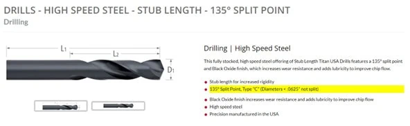
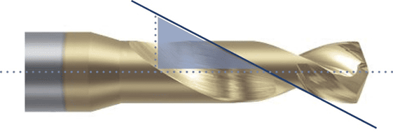
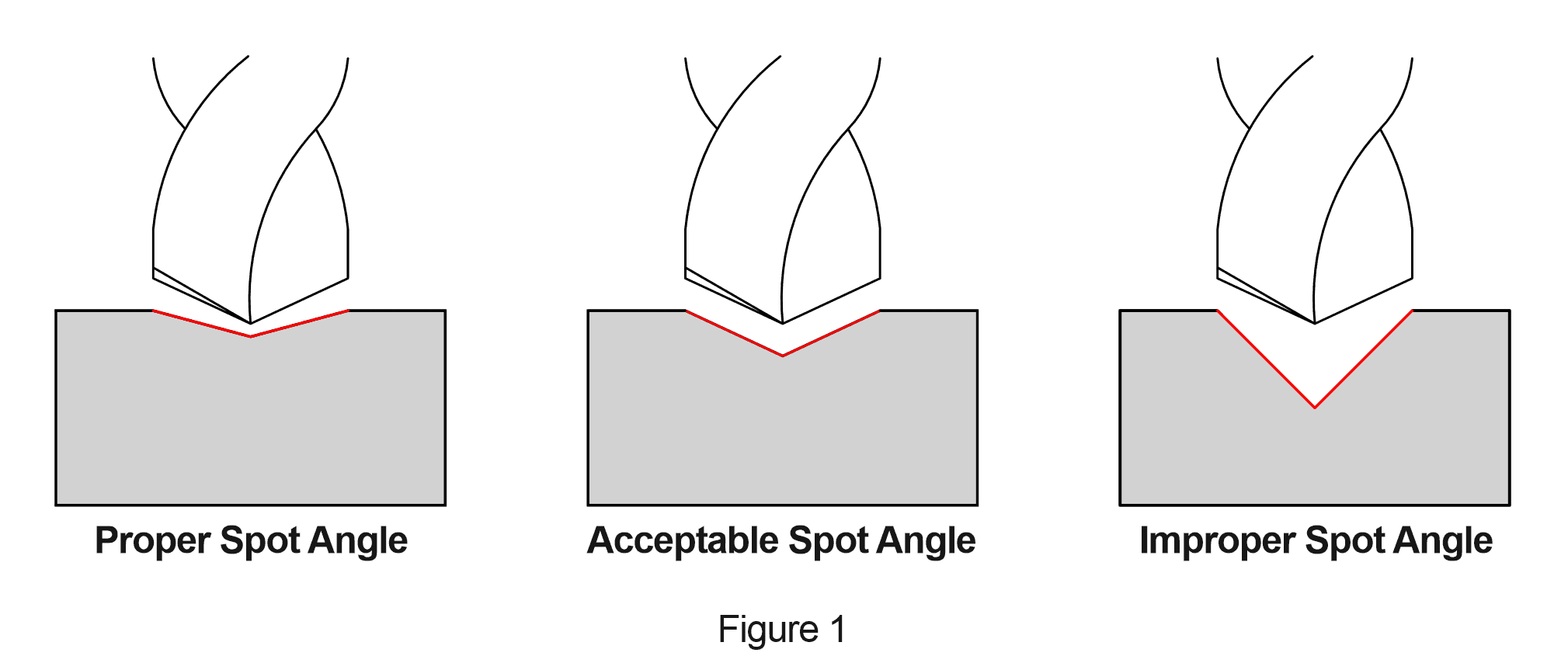
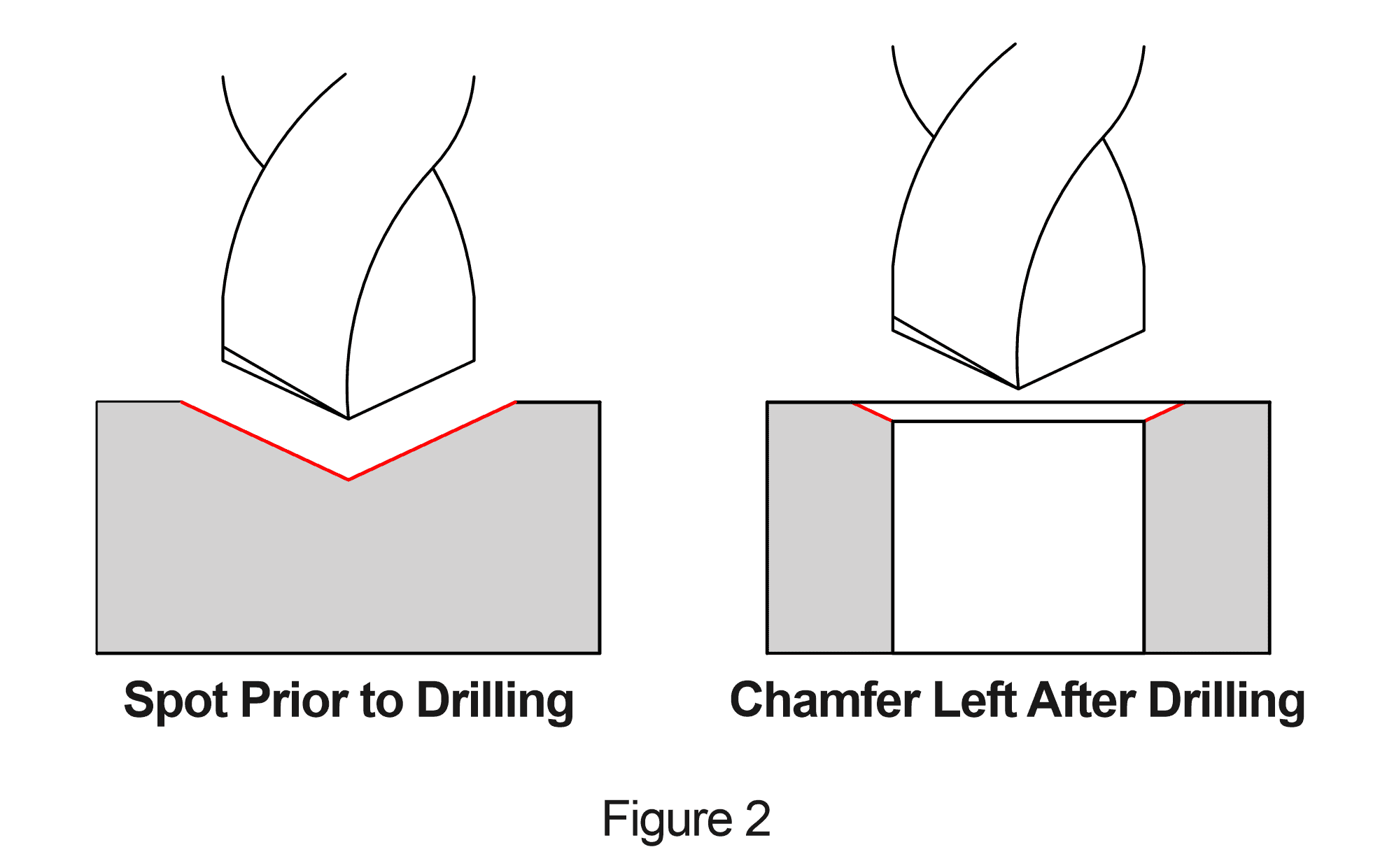
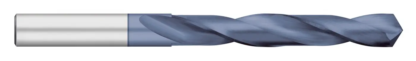
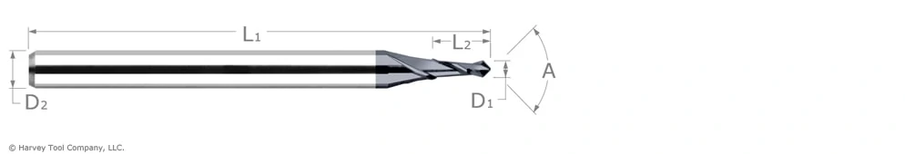
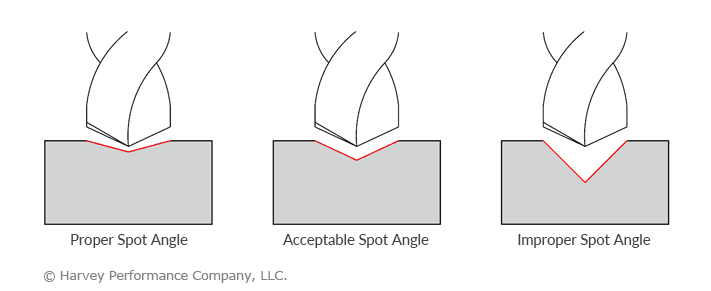
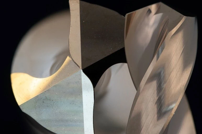
Point Angles
The point angle dictates cutting forces and chip evacuation. Choosing the right angle, such as 118° or 135°, based on material hardness, ensures efficient drilling and prevents walking. The shallower the point angle, the better the distribution of cutting forces on the material. Higher angles walk less, as the point grabs into the material easier.
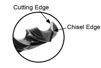
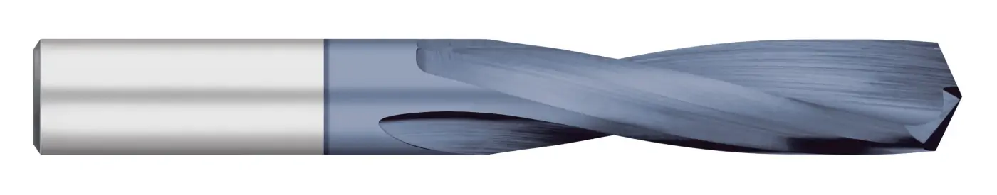
Web Thickness
Web thickness is the distance between cutting edges or flutes at the face of the drill. This is where stability is generated in a tool. Webs that are too thin can increase the likelihood of breakages, while webs that are too thick will generate unnecessary cutting forces. Finding the proper blend of stability and cutting force is a common struggle for machinists.
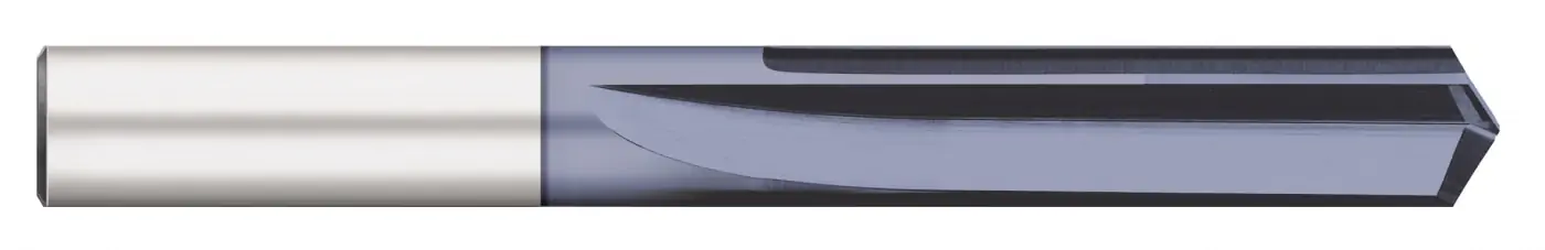
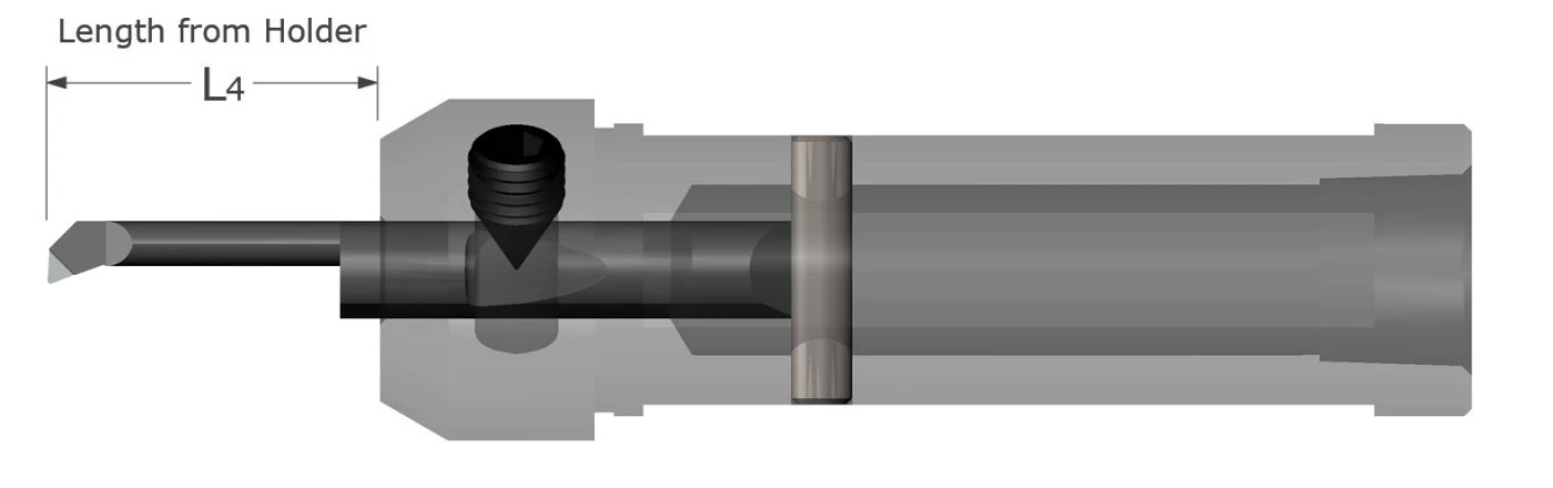
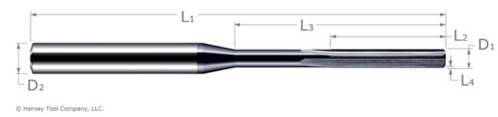
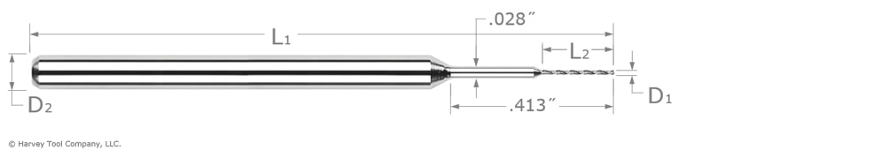
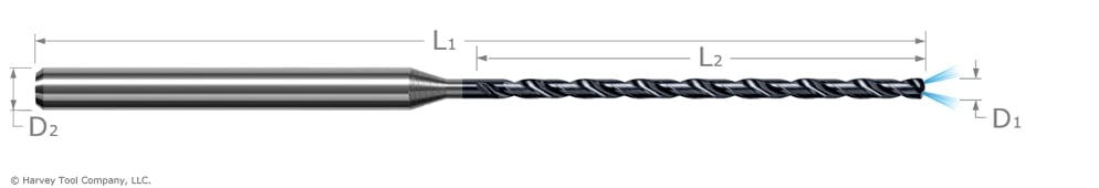
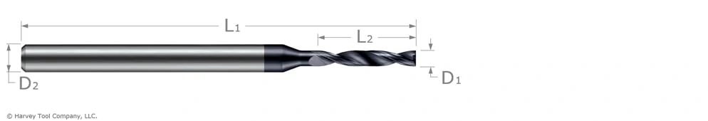
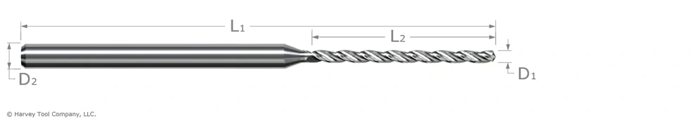
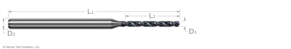
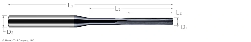
CNC Drill Length Considerations
Flute and overall length impact stability and chip evacuation. Matching these lengths to drilling depth prevents deflection and enhances hole quality. While it may be easiest to purchase a long drill that will work in a variety of scenarios, it is not the best choice to ensure precision. Machinists should best match their required depth to the effective depth of a drill. This ensures that the tool will be as rigid as possible, generating the straightest holes.
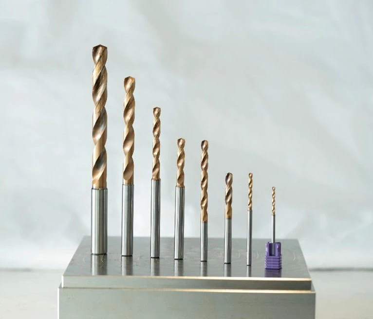
As tool length increases, rigidity decreases. Therefore, a properly matched drill will be as rigid as the situation allows. This affords the machinist with the best possible outcome for their unique drilling application.
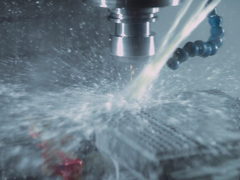
Coolant-Through Drilling
Proper cooling and lubrication extends tool life and ensures excellent hole quality. If your machine is equipped with the option to run through spindle coolant tooling, it can be extremely beneficial to your application. Unlike an end mill, where chips often have the ability to evacuate outward from the tool, the chips in a drilling operating are held captive inside the feature as it’s being drilled, and are only able to evacuate up through the fluting. Through spindle coolant not only cools and lubricates a drill at the point of material removal, but also forcibly evacuates the chips up and out of the hole you’re producing. This can increase your tool’s life and reduce or remove the need for peck cycles all together, which means faster cycle times and higher production rates for your product.
On the other hand, coolant can be fed externally, and sprayed onto the tooling. While this aids in cooling and adding lubricity to the process, it is less efficient than utilizing a coolant-through drill. In deep hole drilling applications, external coolant is often ineffective for chip evacuation efforts, and is not the ideal choice for the best results.
Speeds & Feeds
Optimizing cutting speeds & feeds is essential for efficient and accurate drilling. There is not a “one size fits all approach” for speeds & feeds, as all tools and materials require a slightly different approach. Finding the right balance for each material prevents tool wear and ensures effective chip evacuation. Valor Holemaking offers comprehensive starting parameters in the form of Speeds & Feeds Charts and each tool is also supported by Machining Advisor Pro, which allows machinist to custom generate speeds & feeds based off the exact tool path, material, and machine setup.
Rigidity and Stability
A sturdy machining setup reduces vibrations during drilling, improving hole quality. The same can be said about the drill within. A rigid tool is a stable tool, especially as the depth requirements increase. Stability is especially important for drilling heavy-duty materials. This can be impacted by several factors, most importantly the quality of the tool and its design, as well as its chip management capabilities. High precision and high-performance solid carbide drills are designed for the utmost rigidity to ensure repeatability time after time and part after part.
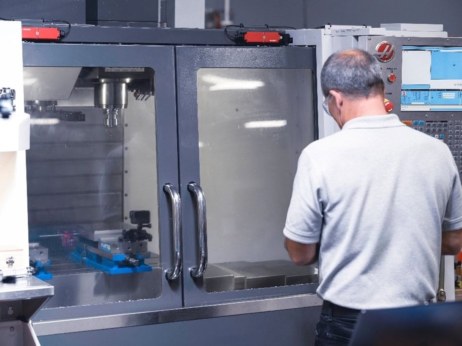
Software and Programming
CNC programming software simplifies creating and editing drilling programs. Compatibility with common CAD/CAM software streamlines integration. Much like machine quality, proper programming is an important step in ensuring precision in CNC drilling applications. CAD/CAM integration ensures the correct dimensions are input to the software to best ensure the tool correctly fits the required parameters.
Exploring Geometries & Key Factors: Wrapped Up
There are many different drill geometries and factors that can directly impact a drill’s performance and hole quality. Understanding these features can greatly assist in your tool selection process, allowing you to improve productivity and hole quality, so you can gain a competitive edge at the spindle.