Multi-Axis Finishers: The Key to Amazing Surface Finish
A Key to Improving Surface Finish
In today’s Manufacturing Industry, part finish and machining efficiency are key to a successful machine shop. It’s no surprise, therefore, that the popularity Multi-Axis Finishers has never been greater. Helical Solutions is a leader in the manufacturing of Multi-Axis Finishers, and its customers utilize this impressive tool when faced with extremely high surface finish requirements, oftentimes swapping out a traditional Ball End Mill to dramatically improve finish while minimizing cycle times.


Multi-Axis Finisher Basic Principles
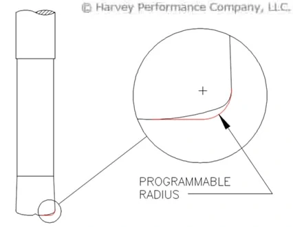
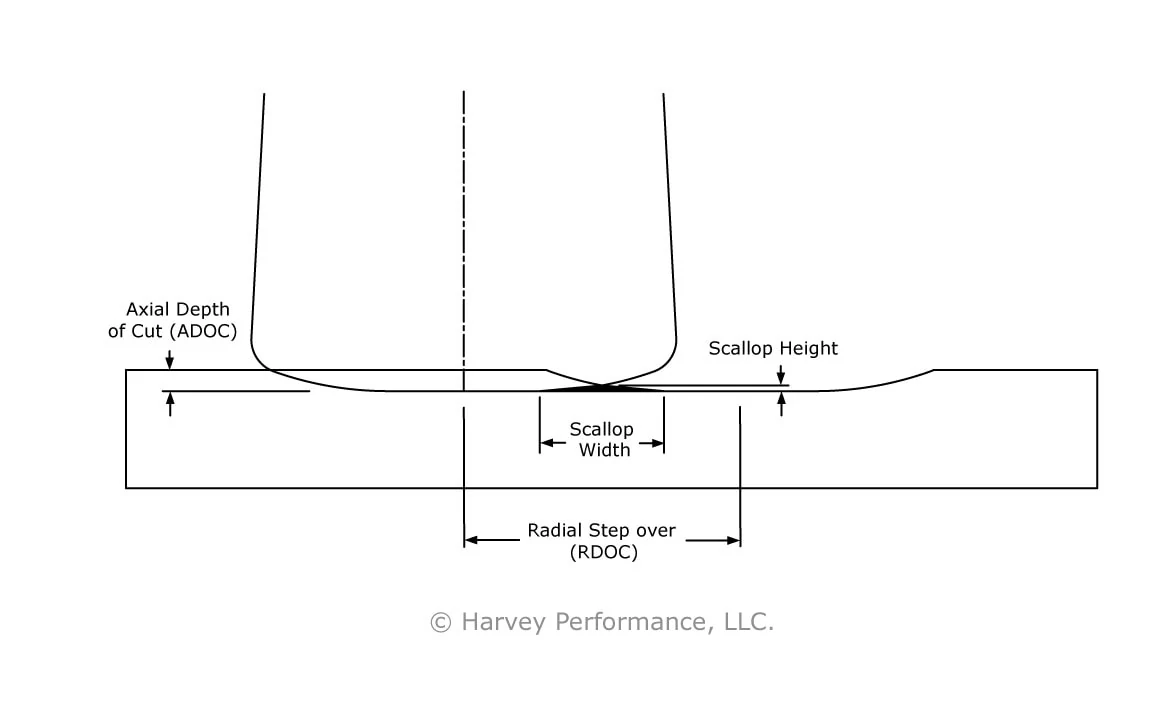
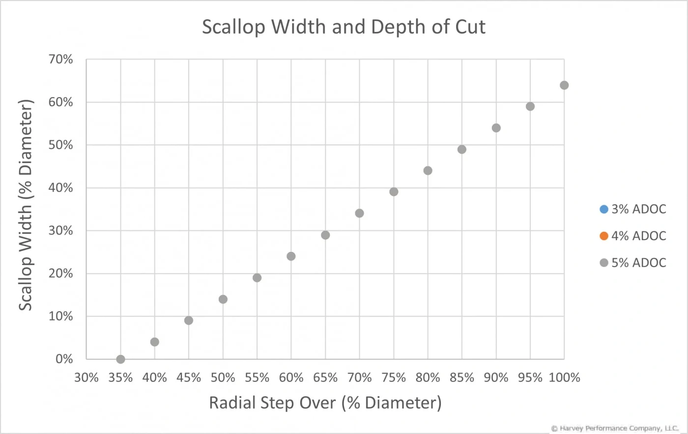
A Multi-Axis Finisher can be easily recognized by its large radius included in the profile of the tool. With a larger radius, a far greater stepover can be used pass-to-pass while keeping the same cusp height as a Ball End Mill. This decreases the cycle time by a known value called the Benefit Multiple.
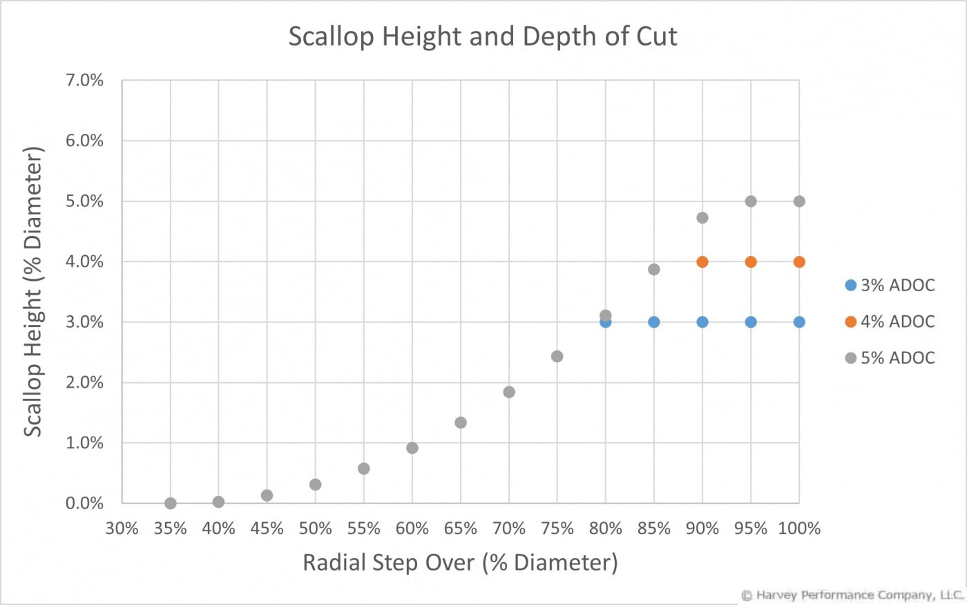
A Multi-Axis Finisher with a Benefit Multiple of 8 will reduce the cycle time to 1/8 of the cycle time for a Ball End Mill of the same shank diameter – an 87.5% time savings! If a Multi-Axis Finisher is used with the same pass-to-pass stepover as a Ball End Mill, the finish will be drastically improved due to exponentially smaller cusp heights. Most situations allow both reduced cycle time and improved surface finish to be achieved.
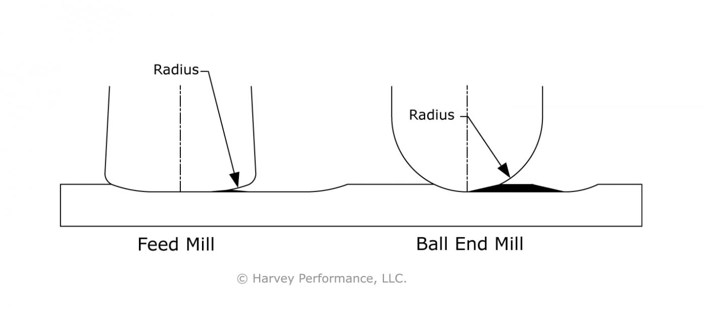
The images below show the comparison of a ball end mill to an Oval Shape Multi-Axis Finisher with a benefit multiple of 4.


Due to their large radii, Multi-Axis Finishers are best suited for wide open, flowing, and somewhat flat surfaces. Smaller spaces, especially tight corners, will generally not see as much benefit from these tools due to limited use of the major radius.
Multi-Axis Finisher Tool Selection
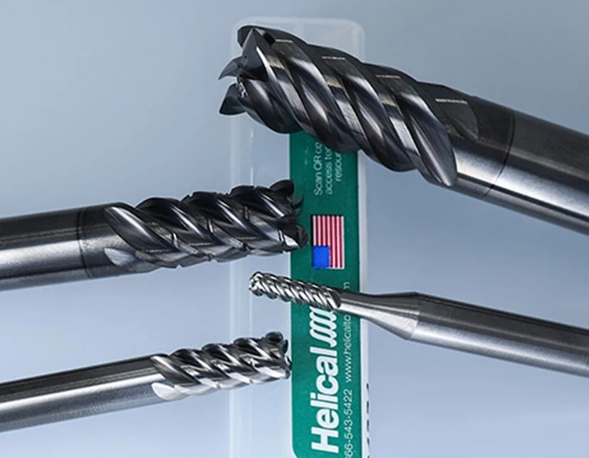
The Manufacturing Industry’s leader in Multi-Axis Finishers, Helical Solutions offers 3 distinct profiles, each fully stocked and available to ship the day of purchase.
Oval Form Multi-Axis Finishers
The oval form includes 2 tangential radii and offers the most versatility in smaller spaces where a slightly varied approach angle is required, such as impellers or fan blades.
Taper Form Multi-Axis Finishers
The taper form includes 3 tangential radii and a taper angle. It allows for the largest radius, and therefore greatest potential improvement of finish and reduction of cycle time. They are best used where a specific approach angle is needed and where maximum performance gain is desired.

Lens Form Multi-Axis Finishers
The lens form includes 2 tangential radii on the end of the tool and is used for work mostly on the face of a part. Tilt angles of approximately 5 degrees are recommended for these tools to avoid working on-center.

Programming Multi-Axis Finishers
Programming Multi-Axis Finishers requires some additional consideration compared to a typical end mill. Luckily, many modern CAM packages offer support for these unique profiles, including many of Helical’s CAM partners. Each software has their own name for these toolpaths, so reach out to your CAM or Helical sales rep to find how you can program yours!
For more information on Multi-Axis Finishers, and to learn if this advantageous tool is right for you, read our Multi-Axis Finishers Q&A.