This website www.harveyperformance.com/in-the-loupe/category/cnc-machining/milling-cnc-machining/ is currently offline. Cloudflare's Always Online™ shows a snapshot of this web page from the Internet Archive's Wayback Machine. To check for the live version, click Refresh.
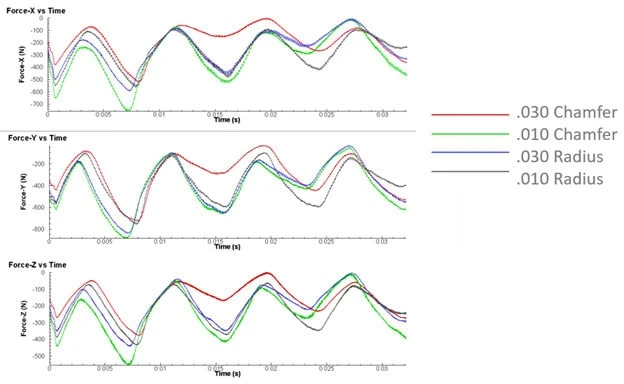
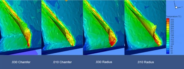
Using Finite Element Analysis (FEA) simulations by Third Wave Systems’ AdvantEdge CAE product, we tested different end mill corner geometries to compare their effects on both the tool and the workpiece. We studied and compared four 4 flute tools with either a 0.010” or 0.030” radius or chamfer. All tools were tested in 304 stainless steel at 1865 RPM, 244 SFM, and 0.0045 IPT for one revolution.
Both Corner Radius and Corner Chamfer tools offer advantages over Square End Mills by improving tool strength and reducing wear, though their benefits vary. One drawback of corner radius end mills is chip thinning along the radius, which can generate excess heat due to changes in chip thickness. This can lead to premature tool wear, poor surface finish, and potential work hardening. On the other hand, Corner Chamfers have the disadvantage of sharp corners where the chamfer meets the outer diameter (OD) and the end of the tool, causing local stress concentrations.
Force Analysis
The graphs above demonstrate the force exerted on the tool during cutting and how the corner size impacts the required force. As each flute engages, the forces peak in each direction. The 0.010” Chamfer generates the greatest force, while the 0.030” Chamfer requires the least. The forces with the radiused tools are very similar and fall between those of the two chamfered tools.
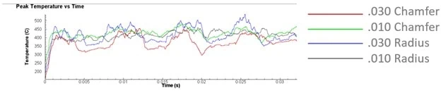
Temperature Analysis
The peak tool temperature graph shows the impact of chip thinning on corner radius tools and the overall corner size. The 0.030” Radius generated the most heat, while the 0.030” Chamfer generated the least. The temperature differences between the 0.010” Chamfer and 0.010” Radius was minimal, with the 0.010” Radius generated slightly less heat.
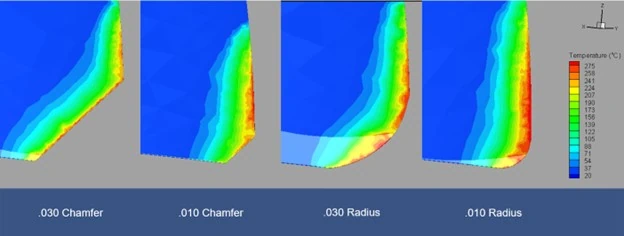
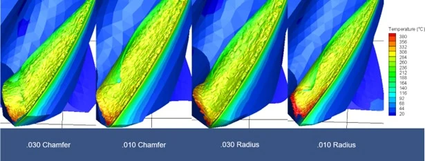
Chip and Workpiece Temperature
Understanding the temperature of the chip and workpiece is crucial for assessing tool performance. The contours above illustrate that the most heat is generated along the 0.030” Radius, followed by the 0.010” Radius. Corner Chamfer tools performed better, maintaining a lower overall temperature due to the absence of chip thinning.
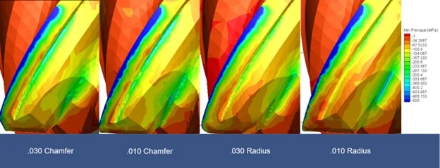
Stress Analysis
The minimum principal stress on the backside of the flute indicates areas prone to tool failure. While there were slight differences between the chamfers and radii, the most notable finding was the reduction in stress with increased corner break size.
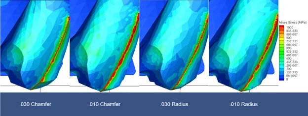
Similarly, the Mises stress analysis shows where stress is concentrated within the tool, potentially leading to failure. Again, the most significant observation was the reduction in stress with larger corner breaks.
Corner Chamfer vs. Corner Radius: Wrapped Up
Considering all factors, the 0.030” Corner Chamfer proved to be the best overall tool for 304 stainless steel. This is partly due to 304’s tendency to work harden, making excess heat generation particularly detrimental. When working with heat-sensitive materials, Corner Chamfer tools are preferable, especially during roughing, as they generate less heat due to the absence of chip thinning. Although there are minor stress concentrations at the sharp corners of Corner Chamfer tools, these are outweighed by the benefits of reduced heat generation. Larger radii exacerbate chip thinning’s impact on heat generation. While both tool styles offer advantages over square end mills, Corner Chamfer tools are more beneficial in high-heat applications where work hardening and tool wear are concerns.
Harvey Tool offers a range of Corner Chamfer Tools, with sizes ranging from 0.047” to 0.500” and various chamfer sizes to suit different applications.
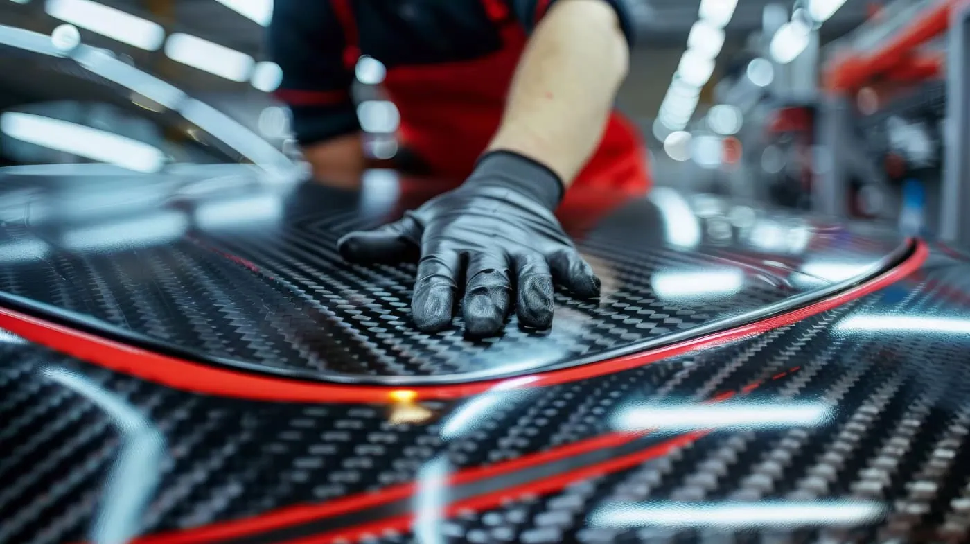
Carbon fiber is a woven cloth made of crystalline filaments of carbon cured with a polymer, which can be layered and shaped around a mold. It is an ideal material due to its impressive strength-to-weight ratio , meaning it’s very strong, but not heavy. Carbon fiber is five times lighter than steel with an equal elastic modulus, making it a better choice for many applications. Further, it is corrosion-resistant, non-flammable, and non-toxic, properties that make it an ideal material to use in aerospace, medical, construction, and military industries.
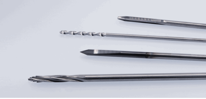
Machining Carbon Fiber
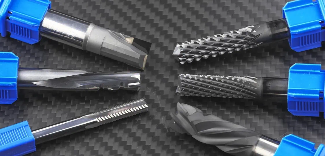
Machining Carbon Fiber can be challenging. The layered structure of the carbon fiber material can lead to delamination, uncut fibers, fiber tear-out, uneven tool wear, and poor surface finishes. Luckily, many cutting tool companies, like CoreHog, specially design tooling with different geometries that can help eliminate these manufacturing problems:
Straight Flute End Mills: Apply all the cutting forces radially, which helps prevent delamination.
Compression Cutters: Create opposite cutting forces, stabilizing material removal and preventing delamination, fiber pullout, and burrs along the surface.
Chipbreaker Cutters: Shear the fibers and shorten the chips, preventing fiber buildup around the cutter.
Diamond Cut End Mills: Utilize both left-hand and right-hand flutes to break up and shear through the fibers, ideal for roughing and profiling carbon fiber.
In the aerospace industry, carbon fiber is used in plane structures to replace alloys, creating lighter planes and thus, reducing fuel consumption. Recreational sports also utilize carbon fiber to decrease weight. It is often seen as a leading material in skis, bikes, and tennis rackets, as the lighter weight can help improve performance. In professional sports leagues like Formula 1 and NASCAR, carbon fiber has grown in prevalence in recent years. Another advantageous quality of carbon fiber is its suitability in X-ray machines, allowing imaging to pass through without interruption, making it useful in many medical devices and implants.
Recycling Carbon Fiber
Why is Recycling Carbon Fiber Difficult?
Carbon fiber sheets require a significant amount of energy to produce. These large sheets are then cut down to the part size needed, and the excess material is often discarded, increasing waste production. This material is not biodegradable and is typically sent to a landfill where it will remain permanently. Further complicating recycling, carbon fiber is built to hold its shape and strength and cannot be melted down and reshaped like many plastics. When recycled, its properties are heavily degraded, rendering it useless for applications that experience heavy forces or loads.
How is Carbon Fiber Recycled?
Solvolysis
Solvolysis uses a chemical solvent to break down the polymer encasing the carbon fiber cloth. The waste carbon fiber is shredded into smaller pieces, increasing the surface area. The solvent, chosen based on the polymers used in the carbon fiber, breaks down the polymer chains, separating the carbon fiber from the polymer. Techniques like centrifugation are used to separate the substances. The carbon fiber can be further purified to restore its properties and then combined with virgin fibers to create new fabric or used by itself. This process enables the recovery of carbon fiber without sacrificing material properties.
Pyrolysis
Pyrolytic utilizes heat to break down the polymer encasing the carbon fiber cloth. The waste carbon fiber is shredded into smaller pieces and then heated in a controlled environment with limited or no oxygen. At high temperatures, the polymer undergoes thermal decomposition, producing gases, vapors, and char. The gases and vapors can be used as an energy source or further processed, while the char, which is carbon fiber and any original additives, is purified to ensure mechanical properties are maintained. The resulting carbon fiber can be used alone or combined with virgin fibers. Pyrolysis is effective for high-quality fiber recovery and energy recovery from gas byproducts.
Carbon Fiber Considerations
As we innovate with new technology, it is important to consider its impact on our planet. Carbon fiber is an amazing material that can improve many aspects across industries; however, the waste generated is not going anywhere but a landfill. Many companies are investing in producing high-quality recycled carbon fiber. With a shift in focus to designing closed-loop systems for composite materials, the future looks bright.
https://www.harveyperformance.com/wp-content/uploads/2024/07/Feature-Image-Recyling-Carbon-Fiber-IMG.jpg5251400Sarah Wassonhttp://www.harveyperformance.com/wp-content/uploads/2018/08/Logo_HarveyPerformanceCompany-4.pngSarah Wasson2024-07-08 12:00:402024-07-12 12:46:58Recycling Carbon Fiber: Importance & Process
Precision cutting plays a pivotal role in the manufacturing of honeycomb core. CoreHog, a leading provider of composite cutting solutions, offers two distinct styles of Finishing Core Tools: Traditional Finishing Core Tools and Free Cutting Tools. In this post, we explore the advantages and limitations of both Traditional Finishing Core Tools and Free Cutting Core Tools, helping you determine the right choice for your unique manufacturing needs.
CoreHog’s Large Core Finishing Tool
Advantages of Traditional Finishing Core Tools:
CoreHog’s Finishing Core Tools are designed to handle substantial cutting tasks, efficiently. With three size ranges available, they excel at removing high volumes of material and boast excellent tool life, making them ideal for production applications.
However, these tools may pose limitations in specific applications. Traditional tools exert tool pressure, but depending on the tool geometry and part profile, the pressure may be too much for the part. This becomes more pronounced when cutting knife edge features such as chamfers and bevels, where the pressure exerted by the tool can cause the part to arch, dislodging it from the table, and ultimately causing it to deviate from specifications.
Introducing Free Cutting Core Finishing Tools:
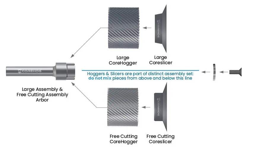
To address the limitations of traditional honeycomb core finishing tools when cutting knife edge features, CoreHog offers Free Cutting Finishing Core Tools. The innovative design reduces tool pressure seen in both the Coreslicer and CoreHogger. The Free Cutting Coreslicer features a more acute and sharper angle, reducing the upward pressure exerted on the part during cutting.
Differentiation of angle between the Large Coreslicer and the Free Cutting Coreslicer
Further, these tools feature a CoreHogger with a reduced diameter, allowing for greater offset between the CoreHogger and Coreslicer. This allows the Coreslicer to be more forward and free cutting, engaging with the material prior to the CoreHogger and reducing the resulting pressure typically exhibited by the CoreHogger.
Reduced diameter design of Free Cutting CoreHogger decreases tool pressure on the part.
When to Use Free Cutting Tools:
CoreHog’s Free Cutting Core Finishing Tools are particularly well-suited for applications involving chamfering, beveling, and cutting angled profiles in honeycomb core materials. By reducing pressure and preventing lifting on the part, these tools ensure precise cuts without compromising part quality.
Traditional vs. Free Cutting Core Finishing Tool: Summarized
In conclusion, choosing the right cutting tool is crucial for achieving precise results in composite manufacturing. While traditional finishing core tools excel in handling substantial tasks, they may pose challenges when cutting angled profiles in honeycomb core materials. CoreHog’s Free Cutting Core Finishing Tools offer a solution by minimizing pressure on the part, making them ideal for chamfering, beveling, and most other angled profiles. However, in finicky applications where the knife edge part is extremely shallow, a Valve Stem Cutter may still be necessary to achieve your desired cut. By understanding your specific cutting requirements, you can select the most suitable tool for your application, ensuring optimal results in your honeycomb manufacturing processes.
https://www.harveyperformance.com/wp-content/uploads/2024/05/Feature-Image-Free-Cutting-Core-Tools.jpg5251400Harvey Performance Companyhttp://www.harveyperformance.com/wp-content/uploads/2018/08/Logo_HarveyPerformanceCompany-4.pngHarvey Performance Company2024-05-16 14:41:282024-07-12 12:47:23Traditional vs. Free Cutting Finishing Core Tools: Which Is Right for Your Application?
Carbon Fiber Reinforced Polymers (CFRP) is a collection of carbon fibers that, when bound together via resin, creates a material with a wide range of application possibilities. It’s strong, durable, and resistant to corrosion, making it an advantageous material for use in several advanced industries, including the aerospace and automotive industries. Despite its unique abilities, however, machining CFRP is not without its set of challenges, all of which machinists must be cognizant of to achieve desired results. Once CFRP is properly understood and the right cutting tool is selected for the job, the next step is to properly set running parameters for your application.
Running Parameters
Comparison of Metal Machining vs Composite Machining
When machining CFRP, the suggested running parameters are to have a high RPM with low feed rates. Feed rates will need to be adjusted to account for heat minimization, while RPMs may need to be dialed back to prevent excessive fraying, tearing, or splitting of fibers when cutting.
In metal machining, the tool cuts away at material, forming chips. This is possible due to the formation of the metal having natural fracture and stress lines that can be wedged by the cutting tool to create a chip. Unlike metals, machining carbon fiber does not peel away material but rather fracture and break the fibers and resin.
Milling vs Drilling Carbon Fiber
Composite holemaking or drilling is found to be more challenging than milling carbon fiber. It generates more dust due to the drilling speed. Using specific tooling for composites will be crucial in effective drilling. When machining holes, the carbon fiber will relax, creating undersized holes which requires extensive adjustments that are best automated for efficiency.
For help mitigating the challenges of composite holemaking, read Overcoming Composite Holemaking Challenges and browse CoreHog’s offering of drills, specially engineered to mitigate all-too-common holemaking headaches. To achieve better finish and avoid delamination, it is recommended to utilize conventional milling over climb milling within composites contrary to what is recommended in metal machining.
Within the aerospace industry, drilling is the most common application in machining. Like milling, performing operations such as pecking may be preferred even with increased cycle time if it reduces any chances of error that result in scrapping of the part.
Running Parallel to Grain of Fibers
While every part is different, there is a method for reducing fraying, chipping, or delamination by cutting parallel to the fiber direction when possible. This can be like cutting along the grain of wood instead of cutting perpendicular or at an angle to the grain.
Coolant Applications
The use of coolant when machining CFRP can either benefit or negatively affect the part depending on the application. The preferred coolant of choice for machining carbon fiber is typically using water or a water-soluble coolant. This is due to composites having a porous surface that could allow contaminates to enter the part itself. By using water, it prevents any issues after machining where adhesives or paint may need to be applied to the part that otherwise would not have adhered properly with contaminates present.
High Scrapping Costs
Many composite parts are unique in shape and size with custom molded designs that create a large initial cost prior to the machining stage. After the part is molded near to its shape, machining is often used to finish the part or drill holes where needed to finalize the part.
Importance of Considering Machining Challenges to Avoid Scrapping
Having a set process that is consistent and reliable is important in helping to prevent scrapping. Eliminating human error with machines that can monitor the entire process while automating tool changes when tools are worn, avoids issues before they can happen. A key factor is ensuring the setup is correct, having the right tooling, tool path, and coolant option to perform the operation effectively and accurately. With some parts serving critical functions and with a high cost, there is no exception for poor finish or incorrect cuts emphasizing the importance of having a procedure that gets the job done the right way.
Composite Cutting Tool Life Management
Wear Rate & its Effects
Due to carbon fiber’s abrasion on the cutting tools, a rapid decrease in cutting quality will occur as soon as the tool begins to dull. Fibers will be grabbed instead of fractured, causing fraying and damage to the part. Therefore, tool life should be vigilantly monitored to replace the tool before reaching the point of dullness.
Developing a Process for Success
Unlike metal machining where tools may be utilized until they show signs of wear, this method would be unideal for CFRP as the highly expensive part could be ruined or damaged causing scrapping costs and time. It is good practice to take preventative measures by taking note of typical wear of your tools and using that information to set tool changes before it dulls. Noting tool changes and having high interval checks on cutting and dimension quality will aid in avoiding poor finish or scrapping. Some machines are equipped with tool life management systems which will greatly reduce the chances of having to scrap a part because of tool dullness.
Safety Practices When Machining CFRP
Being that chips are not formed when machining CFRP, and instead, the material is fractured, it creates dust that can spread throughout the air and other surfaces. Not only does this cause hazardous conditions for anyone nearby who may inhale the dust, but the dust is also conductive, which can ruin electronics. To avoid these issues, two different extraction methods can be used depending on the needs of the application.
Wet vs Dry Extraction
The two options for dust extraction are using coolant (wet) or vacuuming (dry). Choosing between the two is dependent on the application, but mostly dictated by the size of the application. Smaller scale machining can be contained through vacuuming, but larger applications would require coolant as vacuuming a large area may be challenging. If a lot of heat will be generated, then it is necessary to have a water-soluble coolant. This would also benefit the use of diamond tooling as they will wear faster at lower temperatures in comparison to carbide tooling. Another would be the dust collection would remain contained with the liquid preventing any airborne exposure.
Disposal Considerations
One benefit of vacuuming over coolant is the disposal process. After machining, the coolant/dust mix would require post-treatment to remove excess water before being transferred to a landfill. This would incur additional costs to the process which may cause some to lean towards vacuuming if heat is not an issue.
Conclusion
With CFRP’s wide range of uses and desirable mechanical properties for its applications, comes the effect of its challenges in machining and high cost of scrapping. Refining this process will be essential for the growing demand of carbon fiber machining in the near future. For more information on CFRP, specifically related to material properties and tool selection, read In the Loupe’s complementary post “Carbon Fiber Reinforced Polymers (CFRP): Material Properties & Tool Selection”.
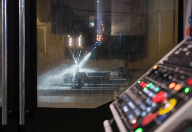
Machinists oftentimes confuse wood for being an “easy to machine material” during CNC Woodworking because of how much softer the material is than metal. In some sense this is true, as you can program wood cutting parameters in CNC Woodworking with much higher feed rates compared to that of most metals. On the other hand, however, wood has many unique properties that need to be accounted for in order to optimize the cutting process for maximum efficiency.
There are 3 main categories of wood for woodworking: hardwood, softwood and engineered wood.
Hardwood
The textbook definition of a hardwood tree is an angiosperm, more commonly referred to as a broadleaf tree. A few examples would be oak, birch, and maple trees. These types of trees are often used for making high quality furniture, decks, flooring, and construction components.
Softwood
A softwood is a coniferous tree, sometimes known as a gymnosperm. These are typically less dense than hardwoods and are therefore associated with being easier to machine. Do not let the name fool you: some soft woods are harder than some hardwoods. Harvey Tool’s Speeds and Feeds Charts for its offering of Material Specific End Mills for Wood are categorized by Janka hardness for this exact reason. Janka hardness is a modified hardness scale with a test specifically designed for classifying types of wood.
Softwood is used to make furniture, but can also be used for doors, window panes, and paper products. A couple of examples are pine and cedar trees. Table 1 lists 20 common woods with their Janka hardness.
Common Name:
Janka Imperial Hardness:
Balsa
90
Buckeye, Yellow
350
Willow, Black
360
Pine, Sugar
380
Cottonwood, Eastern
430
Chesnut, American
540
Pine, Red
560
Douglas-Fir, Interior North
600
Birch, Gray
760
Ash, Black
850
Cedar, Eastern Red
900
Cherry, American Black
950
Walnut, Black
1010
Beech, American
1300
Oak, White
1360
Maple, Sugar
1450
Apple
1730
Cherry, Brazilian
2350
Olive
2700
Rosewood, Indian
3170
Table 1: Janka Hardness of Common Woods
Engineered Woods
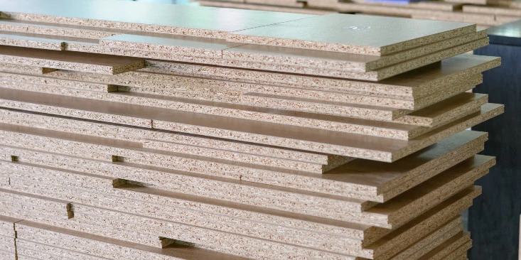
Engineered wood, or composite wood, is any type of wood fiber, particle, or strand material held together with an adhesive or binding agent. Although some of these materials are easier to machine than solid woods, the adhesive holding the material together can be extremely abrasive. This can cause premature tool wear and create difficulties when cnc woodworking. It’s important to note that some types of engineered woods are more difficult to machine than others, specifically those with a higher amount of binding material. These types should be programmed with less aggressive speeds and feeds. For example, medium density fiberboard (MDF) if more difficult to machine than plywood, but much easier to machine than phenolic.
Figure 1: Example of Medium Density Fiberboard
Properties of Wood
Grain Size
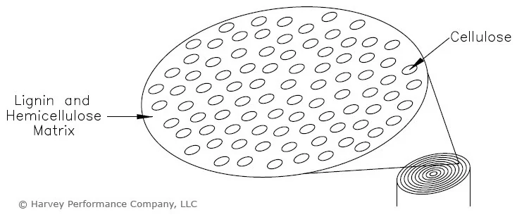
Technically speaking, wood can be considered a natural composite material as it consists of strong and flexible cellulose fibers held together by a stiffer glue-like matrix composed of lignin and hemicellulose. If you think in terms of construction, the cellulose fibers would be the steel rebar, and the concrete would be the lignin and hemicellulose. Wood with large cellulose fibers are considered to be coarse-grained (oak and ash). Woods that have smaller and fewer fibers are considered fine-grained (pine and maple). Softwoods tend to be fine-grained and are therefore stereotyped as being easier to machine since they do not have as many strong fibers to shear. It’s important to note that not all hardwood trees are coarse grained and not all softwood trees are fine-grained.
Figure 2: Simplified diagram of fibers that constitute natural wood. The cellulose fibers run vertically in this depiction.
Moisture Content (MC)
Moisture content (MC) is one of the most important variables to consider when machining wood. An extremely common problem with building anything with wood is its tendency to warp. Moisture variability in the air inevitably affects the moisture content within the wood. Any change in moisture content (whether an increase or a decrease) will disturb the shape of the workpiece. This is why one must take into account what type of moisture a product will be exposed to in its final resting place.
Equilibrium Moisture Content (EMC)
Equilibrium moisture content (EMC) occurs when wood has reached a balance point in its moisture content. Interior EMC values across the United States average at about 8%, with exterior values averaging around 12%. These values vary around the country due to the differences in temperature and humidity. For example, the southeastern United States have an average interior EMC of 11% while the southwest averages about 6% (excluding the coastal region). It’s important to consider what region and application the final product is going to encounter so that the wood with the correct moisture content can be selected before machining. Most species of flat-grain wood will change size 1% for every 4% change in MC. The direction of warping depends on the grain orientation.
Figure 4: Average regional indoor EMC
Generally, power requirements for an operation rise with increasing moisture content, mainly because of the surge in density. Density of wood increases with rising MC. The additional power may be necessary to push a heavier chip out of the cutting zone during CNC Woodworking. It’s worth noting that, like synthetic polymers, wood is a viscoelastic material that absorbs energy as it becomes wetter. The proportional limit of its mechanical properties intensifies as MC increases.
When machining some types of wood, cutting region temperature will surge with increasing MC, but in other species it will decline. Be safe and avoid rapid tool wear by decreasing SFM when machining a wood with a moisture content above 10%. Harvey Tool Speeds and Feeds Charts suggest a decrease of 30 per MC percentage point. As always, though, it depends on the type of wood being machined and the type of operation being performed.
Temperature change is not the only reason higher moisture content is associated with rapid tool wear. Moisture within wood isn’t just associated with water, but also with resins, sugars, oils, starches, alkaloids, and tannin present within the water. These substances react particularly well with high speed steel, and to a lesser degree with carbide.
Knots and Their Effect on CNC Woodworking
A knot is a portion of a branch or limb that has become incorporated in the trunk of a tree. The influence of knots on the mechanical properties of wood is due to the interruption of continuity and change in direction of wood fibers associated with it. These properties are lower in this portion of the wood because the fibers around the knot are distorted and lead to stress concentrations. “Checking” (cracking due to shrinking) often occurs around knots during drying. Hardness and strength perpendicular to the grain are exceptions to generally lower mechanical properties. Because of these last two exceptions, woodworking machining parameters should be reduced when encountering a knotted portion of the workpiece to avoid shock loading.
Whether your tool is a 1” diameter powerhouse rougher or a .032” precision end mill, slotting is one of the hardest operations on the tool. During slotting operations, a lot of force and pressure is placed on the entire cutting edge of the tool. This results in slower speeds and feeds and increased tool wear, making it one of the nastier processes even for the best cutting tools.
With miniature tooling (for the purposes of this blog, under 1/8” diameter) the game changes. The way we approach miniature tooling is completely different as it relates to slotting. In these instances, it is vitally important to select the correct tool for these operations. A few of the suggestions may surprise you if you are used to working with larger tooling, but rest assured, these are tried and tested recommendations which will dramatically increase your success rate in miniature slotting applications.
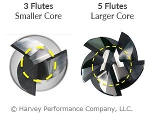
Use as Many Flutes as Possible
When running traditional slotting toolpaths, the biggest concern with the cutting tool is getting the best chip evacuation by using the proper flute count. Traditionally speaking, you want to use the fewest amount of flutes possible. In Aluminum/Non-Ferrous jobs, this is typically no more than 2/3 flutes, and in Steel/Ferrous applications, 4 flutes is recommended. The lower flute count leaves room for the chips to evacuate so you are not re-cutting chips and clogging the flutes on your tool in deep slots.
When slotting with miniature tools, the biggest concerns are with tool rigidity, deflection, and core strength. With micro-slotting we are not “slotting”, but rather we are “making a slot”. In traditional slotting, we may drive a ½” tool down 2xD into the part to make a full slot, and the tool can handle it! But this technique simply isn’t possible with a smaller tool.
For example, let’s take a .015” end mill. If we are making a slot that is .015” deep with that tool, we are likely going to take a .001” to .002” axial depth per pass. In this case, chips are no longer your problem since it is not a traditional slotting toolpath. Rigidity and core strength are now key, which means we need to add as many flutes as possible! Even in materials like Aluminum, 4 or 5 flutes will be a much better option at smaller diameters than traditional 2/3 flute tools. By choosing a tool with a higher flute count, some end users have seen their tool life increase upwards of 50 to 100 times over tools with lower flute counts and less rigidity and strength.
Use the Strongest Corner Possible When Slotting
Outside of making sure you have a strong core on your miniature tools while making a slot, you also need to take a hard look at your corner strength. Putting a corner radius on your tooling is a great step and does improve the corner strength of the tool considerably over a square profile tool. However, if we want the strongest tip geometry, using a ball nose end mill should also be considered.
A ball nose end mill will give you the strongest possible tip of the three most common profiles. The end geometry on the ball nose can almost work as a high feed end mill, allowing for faster feed rates on the light axial passes that are required for micro-slotting. The lead angle on the ball nose also allows for axial chip thinning, which will give you better tool life and allow you to decrease your cycle times.
A .078″ ball nose end mill was used for this miniature slotting operation
Finding the Right Tool for Miniature Slotting Operations
Precision and accuracy are paramount when it comes to miniature tooling, regardless of whether you are slotting, roughing, or even simply looking to make a hole in a part. With the guidelines above, it is also important to have a variety of tooling options available to cater to your specific slotting needs. Harvey Tool offers 5 flute end mills down to .015” in diameter, which are a great option for a stronger tool with a high flute count for slotting operations.
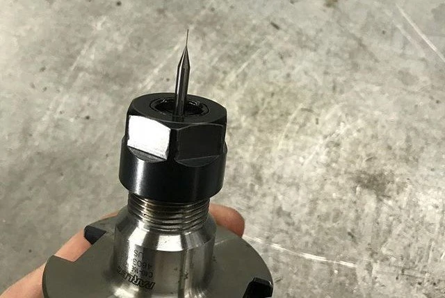
Harvey Tool offers many miniature end mill options, like the .010″ long reach end mill above.
If you are looking to upgrade your corner strength, Harvey Tool also offers a wide selection of miniature end mills in corner radius and ball nose profiles, with dozens of reach, length of cut, and flute count options. Speeds and feeds information for all of these tools is also available, making your programming of these difficult toolpaths just a little bit easier.
Achieving Slotting Success: Summary
To wrap things up, there are three major items to focus on when it comes to miniature slotting: flute count, corner strength, and the depth of your axial passes.
It is vital to ensure you are using a corner radius or ball nose tool and putting as many flutes as you can on your tool when possible. This keeps the tool rigid and avoids deflection while providing superior core strength.
For your axial passes, take light passes with multiple stepdowns. Working your tool almost as a high feed end mill will make for a successful slotting operation, even at the most minuscule diameters.
The machining industry generally considers micromachining and miniature end mills to be any end mill with a diameter under 1/8 of an inch. This is also often the point where tolerances must be held to a tighter window. Because the diameter of a tool is directly related to the strength of a tool, miniature end mills are considerably weaker than their larger counterparts, and therefore, lack of strength must be accounted for when micromachining. If you are using these tools in a repetitive application, then optimization of this process is key.
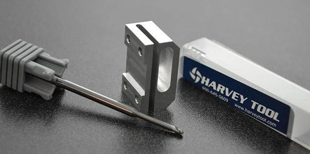
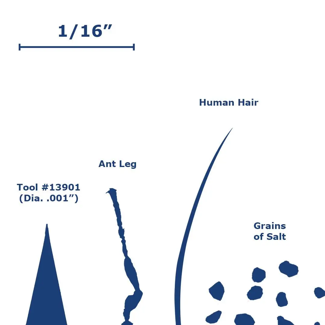
Size Comparison for Harvey Tool’s #13901 Square Miniature End Mill
Key Cutting Differences Between Conventional and Miniature End Mills
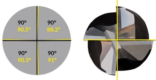
Runout
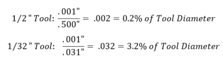
Runout during an operation has a much greater effect on miniature tools, as even a very small amount can have a large impact on the tool engagement and cutting forces. Runout causes the cutting forces to increase due to the uneven engagement of the flutes, prompting some flutes to wear faster than others in conventional tools, and breakage in miniature tools. Tool vibration also impacts the tool life, as the intermittent impacts can cause the tool to chip or, in the case of miniature tools, break. It is extremely important to check the runout of a setup before starting an operation. The example below demonstrates how much of a difference .001” of runout is between a .500” diameter tool and a .031” diameter tool.
The runout of an operation should not exceed 2% of the tool diameter. Excess runout will lead to a poor surface finish.
Chip Thickness
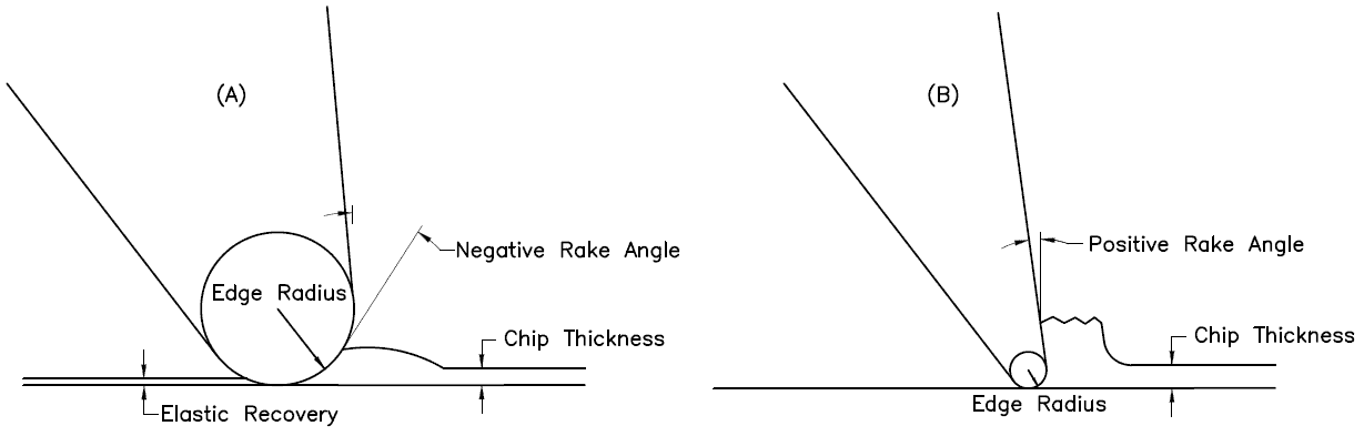
The ratio between the chip thickness and the edge radius (the edge prep) is much smaller for miniature tools. This phenomena is sometimes called “the size effect” and often leads to an error in the prediction of cutting forces. When the chip thickness-to-edge radius ratio is smaller, the cutter will be more or less ploughing the material rather than shearing it. This ploughing effect is essentially due to the negative rake angle created by the edge radius when cutting a chip with a small thickness.
If this thickness is less than a certain value (this value depends of the tool being used), the material will squeeze underneath the tool. Once the tool passes and there is no chip formation, part of the plowed material recovers elastically. This elastic recovery causes there to be higher cutting forces and friction due to the increased contact area between the tool and the workpiece. These two factors ultimately lead to a greater amount of tool wear and surface roughness.
Figure 1: (A) Miniature tool operation where the edge radius is greater than the chip thickness (B) Conventional operation where the edge radius is small than the chip thickness
Tool Deflection in Conventional vs. Micromachining Applications
Tool deflection has a much greater impact on the formation of chips and accuracy of the operation in micromachining operations, when compared to conventional operations. Cutting forces concentrated on the side of the tool cause it to bend in the direction opposite the feed. The magnitude of this deflection depends upon the rigidity of the tool and its distance extended from the spindle. Small diameter tools are inherently less stiff compared to larger diameter tools because they have much less material holding them in place during the operation. In theory, doubling the length sticking out of the holder will result in 8 times more deflection. Doubling the diameter of an end mill it will result in 16 times less deflection. If a miniature cutting tool breaks on the first pass, it is most likely due to the deflection force overcoming the strength of the carbide. Here are some ways you can minimize tool deflection.
Workpiece Homogeny
Workpiece homogeny becomes a questionable factor with decreasing tool diameter. This means that a material may not have uniform properties at an exceptionally small scale due to a number of factors, such as container surfaces, insoluble impurities, grain boundaries, and dislocations. This assumption is generally saved for tools that have a cutter diameter below .020”, as the cutting system needs to be extremely small in order for the homogeny of the microstructure of the material to be called into question.
Surface Finish
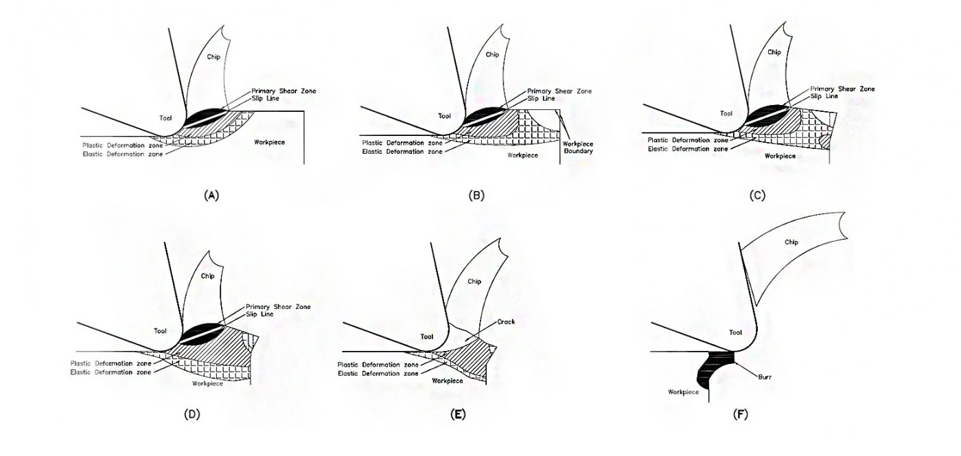
Micromachining may result in an increased amount of burrs and surface roughness when compared to conventional machining. In milling, burring increases as feed increases, and decreases as speed increases. During a machining operation, chips are created by the compression and shearing of the workpiece material along the primary shear zone. This shear zone can be seen in Figure 2 below. As stated before, the chip thickness-to-edge radius ratio is much higher in miniature applications. Therefore, plastic and elastic deformation zones are created during cutting and are located adjacent to the primary shear zone (Figure 2a). Consequently, when the cutting edge is close to the border of the workpiece, the elastic zone also reaches this border (Figure 2b). Plastic deformation spreads into this area as the cutting edge advances, and more plastic deformation forms at the border due to the connecting elastic deformation zones (Figure 2c). A permanent burr begins to form when the plastic deformation zones connect (Figure 2d) and are expanded once a chip cracks along the slip line (Figure 2e). When the chips finally break off from the edge of the workpiece, a burr is left behind (Figure 2f).
Figure 2: Burr formation mechanism using a miniature end mill
Tool Path Best Practices for Miniature End Mills
Because of the fragility of miniature tools, the tool path must be programmed in such a way as to avoid a sudden amount of cutting force, as well as permit the distribution of cutting forces along multiple axes. For these reasons, the following practices should be considered when writing a program for a miniature tool path:
Ramping Into a Part
Circular ramping is the best practice for moving down axially into a part, as it evenly distributes cutting forces along the x, y, and z planes. If you have to move into a part radially at a certain depth of cut, consider an arching tool path as this gradually loads cutting forces onto the tool instead of all at once.
Micromachining in Circular Paths
You should not use the same speeds and feed for a circular path as you would for a linear path. This is because of an effect called compounded angular velocity. Each tooth on a cutting tool has its own angular velocity when it is active in the spindle. When a circular tool path is used, another angular velocity component is added to the system and, therefore, the teeth on the outer portion of tool path are traveling at a substantially different speed than expected. The feed of the tool must be adjusted depending on whether it is an internal or external circular operation. To find out how to adjust your feed, check out this article on running in circles.
Do not approach a miniature slot the same way as you would a larger slot. With a miniature slot, you want as many flutes on the tool as possible, as this increases the rigidity of the tool through a larger core. This decreases the possibility of the tool breaking due to deflection. Because there is less room for chips to evacuate with a higher number of flutes, the axial engagement must be decreased. With larger diameter tools you may be stepping down 50% – 100% of the tool diameter. But when using miniature end mills with a higher flute count, only step down between 5% – 15%, depending on the size of the diameter and risk of deflection. The feed rate should be increased to compensate for the decreased axial engagement. The feed can be increased even high when using a ball nose end mill as chip thinning occurs at these light depths of cut and begins to act like a high feed mill.
Slowing Down Your Feed Around Corners
Corners of a part create an additional amount of cutting forces as more of the tool becomes engaged with the part. For this reason it is beneficial to slow down your feed when machining around corners to gradually introduce the tool to these forces.
This is somewhat of a tricky question to answer when it comes to micromachining. Climb milling should be utilized whenever a quality surface finish is called for on the part print. This type of tool path ultimately leads to more predictable/lower cutting forces and therefore higher quality surface finish. In climb milling, the cutter engages the maximum chip thickness at the beginning of the cut, giving it a tendency to push away from the workpiece. This can potentially cause chatter issues if the setup does not have enough rigidity. In conventional milling, as the cutter rotates back into the cut it pulls itself into the material and increases cutting forces. Conventional milling should be utilized for parts with long thin walls as well as delicate operations.
Combined Roughing and Finishing Operations
These operations should be considered when micromachining tall thin walled parts as in some cases there is not sufficient support for the part for a finishing pass.
Helpful Tips for Achieving Successful Micromachining Operations With Miniature End Mills
Try to minimize runout and deflection as much as possible when micromachining with miniature end mills. This can be achieved by using a shrink-fit or press-fit tool holder. Maximize the amount of shank contact with the collet while minimizing the amount of stick-out during an operation. Double check your print and make sure that you have the largest possible end mill because bigger tools mean less deflection.
Choose an appropriate depth of cut so that the chip thickness to edge radius ratio is not too small as this will cause a ploughing effect.
If possible, test the hardness of the workpiece before machining to confirm the mechanical properties of the material advertised by the vender. This gives the operator an idea of the quality of the material.
Use a coated tool if possible when working in ferrous materials due to the excess amount of heat that is generated when machining these types of metals. Tool coatings can increase tool life between 30%-200% and allows for higher speeds, which is key in micro-machining.
Consider using a support material to control the advent of burrs during a micromachining application. The support material is deposited on the workpiece surface to provide auxiliary support force as well as increase the stiffness of the original edge of the workpiece. During the operation, the support material burrs and is plastically deformed rather than the workpiece.
Use flood coolant to lower cutting forces and a greater surface finish.
Scrutinize the tool path that is to be applied as a few adjustments can go a long way in extending the life of a miniature tool.
Double-check tool geometry to make sure it is appropriate for the material you are machining. When available, use variable pitch and variable helix tools as this will reduce harmonics at the exceptionally high RPMs that miniature tools are typically run at.
Figure 3: Variable pitch tool (yellow) vs. a non-variable pitch tool (black)
https://www.harveyperformance.com/wp-content/uploads/2020/07/Feature-Image-Machining-with-Miniature-End-Mills-IMG-1.jpg5251400Robert Keeverhttp://www.harveyperformance.com/wp-content/uploads/2018/08/Logo_HarveyPerformanceCompany-4.pngRobert Keever2020-07-01 10:43:432024-02-08 15:36:10How to Optimize Results While Machining With Miniature End Mills
When the manufacturing team at Geospace Technologies was looking for better tool life and improved performance on a Titanium CNC milling job, they turned to Harvey Performance Company and local Application Engineer Mike Kanigowski to dial in some Helical Solutions End Mills. With Mike’s help, Geospace Technologies, led by Lead Mill Programmer Tranquilino Sosa, achieved massive success and extensive titanium machining cost savings, which led them to completely shift their tooling repertoire to Helical’s high-performance end mills in their shop.
Struggling With Tool Life
Prior to switching to Helical, Geospace Technologies was experiencing trouble with tool life on a job that required both roughing and finishing toolpaths on a Titanium (Ti-6AL-4V) part. For their roughing pass, Geospace was using a competitor’s 4 flute, 3/8” diameter end mill with a 30° helix angle and TiALN coating. In traditional roughing toolpaths, this tool was running at 1,750 RPM with a 10 IPM feed rate. The tool would take four step downs, three with an axial depth of cut of .200”, and a final pass at .100” for a total depth of .700”.
When finishing, the team used a 1/2” version of the same competitor tool, running at 900 RPM with an 8 IPM feed rate. This would take two passes, one at .400” deep and the last down to the bottom of the part at .700”.
With this strategy and tooling, the team was creating high-quality parts at a cycle time of 15 minutes and 22 seconds per part, but were only seeing the roughing tool last for 60 parts on average, and the finishing tool for around 120 parts. This was causing tool costs to be higher than they would like, and costing the team precious time with frequent tool changes.
Sosa had seen some of the success that other shops were having with Titanium milling using Helical Solutions end mills, and so they reached out to Kanigowski to see how Helical could help them lower their cost per part while achieving an even better finish.
Dialing in Tool Selection
When Mike got in touch with the team at Geospace, he knew there were some immediate benefits to changing the toolpaths used in this job. Using their ESPRIT software, the team was able to dial in a new program using high efficiency milling (HEM) toolpaths through ESPRIT’s “Profit Milling” technology.
With HEM toolpaths in place, Geospace was going to need new high performance tools to take full advantage of the programming adjustments. After much testing and evaluating several options from Helical’s extensive line of end mills for Titanium, Geospace settled on two solid tools.
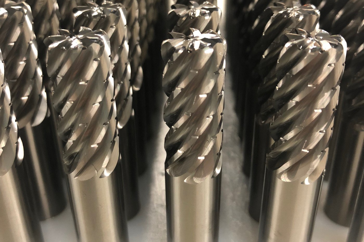
Helical offers many different options for Titanium milling in HEM toolpaths. During testing, the team at Geospace decided on Helical EDP 59424, a 3/8” diameter, 7 flute, corner radius end mill. This tool features variable pitch geometry and offset chipbreakers for optimal chip evacuation, reduced harmonics, and minimized tool pressure, as well as Helical’s Aplus coating for high temperature resistance, decreased wear, and improved tool life.
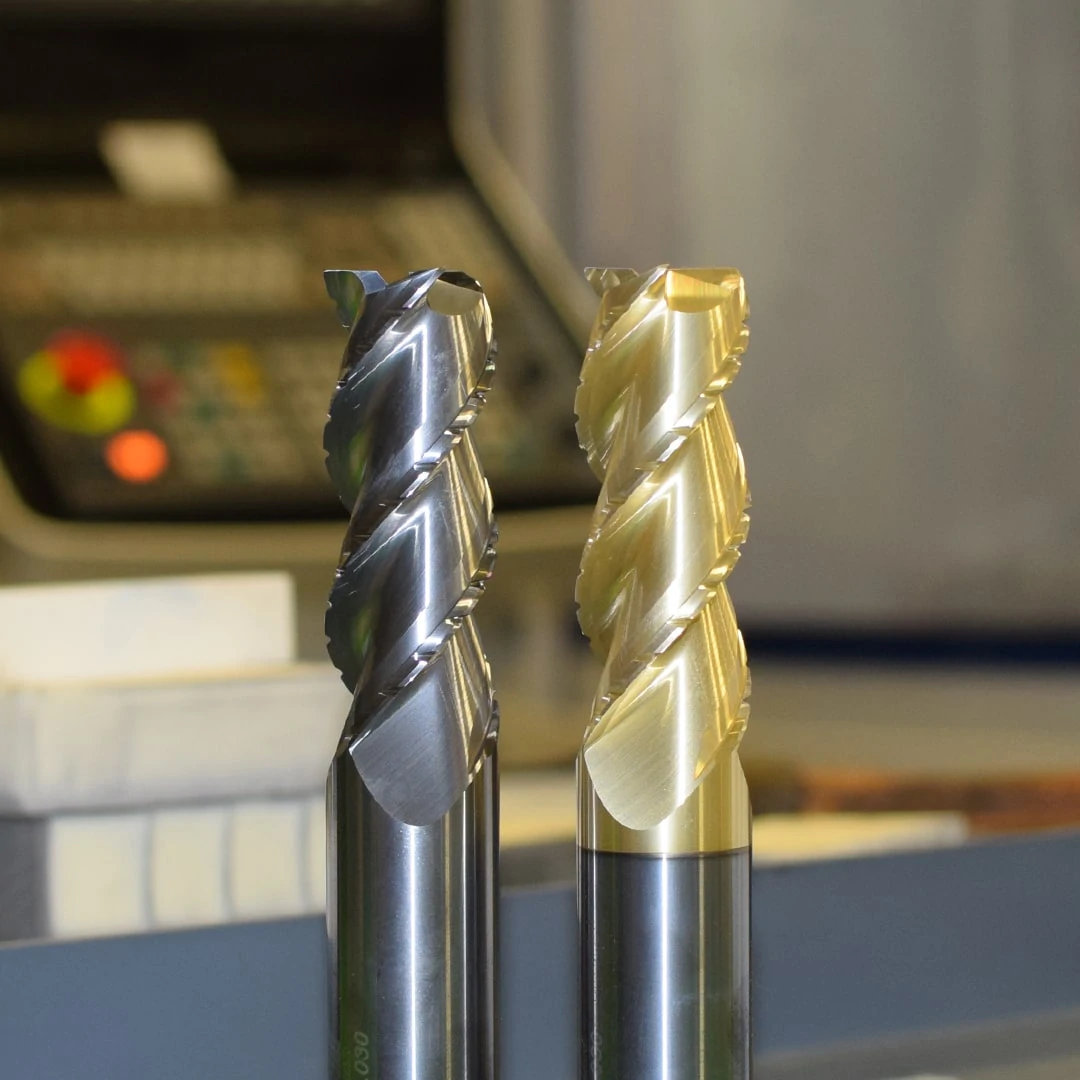
7 Flute Chipbeaker Tools Fresh Off the Grinder
When looking at the finishing toolpath, Geospace decided on Helical EDP 82566, a 3/8”, 6 flute, square end mill from Helical’s well known HEV-6 product line. This tool featured a variable pitch design to help mitigate chatter and leave a superior finish. While Helical also offers several tools for finishing toolpaths in Titanium, during testing this tool provided Geospace with the best finish for their specific part geometry.
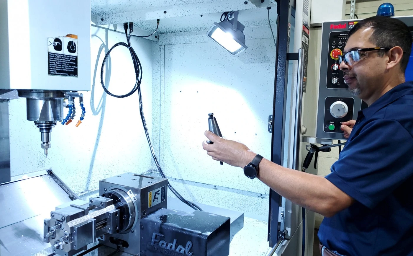
With the new tools in place, Sosa’s team reached out to Helical for help dialing in speeds and feeds. The Helical tech team was able to get them set up on Machining Advisor Pro, an advanced speeds and feeds calculator developed by the experts behind Helical Solutions tooling. With this “miracle worker” application in their arsenal, the team was able to easily dial in their new tools for their specific material grade, depth of cut, and machine setup.
The team saw immediate positive results and cost-savings on this job. They were able to increase their roughing toolpaths to 4,500 RPM and 157 IPM. The finishing path remained largely the same, but resulted in a much improved final part. In total, cycle time dropped from 15 minutes and 22 seconds per part to 12 minutes and 17 seconds per part, which was great, but the improvement in tool life was where Sosa was most impressed.
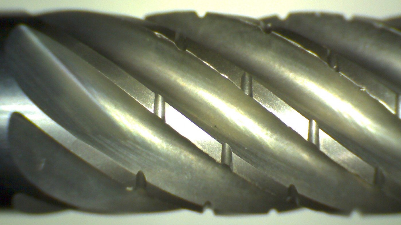
With the new Helical end mill in the shop, Geospace was able to run both tools for 580 parts with very minimal wear on the tool. This was a nearly 1000% improvement in tool life for their roughing passes and a 483% improvement in tool life for the finishing operation. In total, one roughing tool was able to last more than 42 hours in the cut before needing to be replaced.
Eliminating the need for a tool change every 60 parts was also a significant time-saver. Constant tool changes were causing serious machine downtime, which was eliminated with the longer tool life experienced with the Helical end mills. What seems like a minor inconvenience will truly add up to dozens of hours in saved time over the course of a few months for Sosa’s team.
A Closeup of the 7 Flute Chipbreaker After 42 Hours In The Cut
Geospace was thrilled with the results they saw on this Titanium job, as they had never experienced long tool life in Titanium with any other competitor brand. Sosa and his team are excited to continue using Helical Solutions product across all of their other jobs going forward and to continue working with Kanigowski and the Helical tech team on dialing in tool selection and speeds and feeds on future projects.
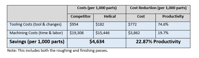
Please see below for a head-to-head breakdown of the Helical end mills’ performance in terms of total costs and productivity gained versus that of the competitor. These numbers are measured per 1,000 parts, taking into account tooling costs, tool change time, labor costs, running parameters, and cycle times.
When many people think about solid carbide tools with chip breakers, they are usually tooling up for a roughing application. While the chipbreaker tool is a great choice for such applications, it can be utilized in a number of other areas too. In this post, we’ll examine many other benefits of the chip breaker style of tooling.
High Efficiency Milling (HEM)
High Efficiency Milling (HEM) uses CAM software to program advanced toolpaths that reduce cutting forces. These tool paths employ smaller end mills with a higher number of flutes (for a stronger core) running at higher speeds and feeds. This strategy includes a light radial depth of cut (RDOC), high axial depth of cut (ADOC), and a controlled angle of engagement.
Helical’s chipbreaking tools include serrated indents along the edge of flute for the entire length of cut. Because HEM utilizes heavy axial depths of cuts, these tools are able to break long chips into smaller ones. In addition to improving chip control and reducing cutting resistance, chipbreaker tools also help in decreasing heat load within the chips. This delays tool wear along the cutting edge and improves cutting performance.
Check out this testimony from a Helical Solutions customer:
“We were able to get going with the 7 flute tools with the chipbreaker. I have to say the difference was INCREDIBLE! We can now rough the entire part with one tool. Also, the operator doesn’t have to open the door to clear chips hardly at all. We were able to rough and finish a 4.15 dia. bore 2 inches deep through the part without having to clear chips at all. Before we had to clear the chips out at least 15-20 times. Many thanks for your support.”
When slotting, a major concern is chip control. A large buildup of chips can cause the recutting of chips, which adds a lot of heat back into the tool. Chip buildup can also cause a heavy amount of chattering. Both of these conditions are detrimental to tool life. A chip breaking tool can help reduce chip build-up when slotting which will extend tool life. Remember when slotting that 4 flute tools should be utilized in steel. For aluminum and other non- ferrous materials, a 3 flute tool is best.
Trochoidal slotting is a form of slotting that uses HEM techniques to form a slot. Trochoidal milling implements a series of circular cuts to create a slot wider than the cutting tool’s cutting diameter. Using the logic listed in the earlier paragraphs of this article, a chipbreaker should be used when performing this operation.
Advantages of Trochoidal Slotting:
Decreased
cutting forces
Reduced
heat
Greater
machining accuracy
Improved
tool life
Faster
cycle times
One
tool for multiple slot sizes
Finishing
A little known fact about Helical’s chipbreaker style tool is that the chip breakers are offset flute to flute, which allows for a quality finish on the walls of the part. When utilizing light depths of cuts, high-quality finishes can be achieved.
https://www.harveyperformance.com/wp-content/uploads/2020/04/Feature-Image-Chipbreaker-Tooling-IMG.jpg6001599Ben Holmhttp://www.harveyperformance.com/wp-content/uploads/2018/08/Logo_HarveyPerformanceCompany-4.pngBen Holm2020-04-17 11:48:112021-11-19 08:35:51Chipbreaker Tooling: Not Just for Roughing
Many types of steel have a beneficial response to a method of heat treatment known as quenching. One of the most important criteria in the selection process of a workpiece material is hardenability. Hardenability describes how deep a metal can be hardened upon quenching from high temperature, and can also be referred to as the depth of hardening.
Steel At Microscopic Scale:
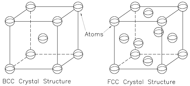
The first level of classification of steels at a microscopic level is their crystal structure, the way in which atoms are arranged in space. Body-Centered Cubic (BCC) and Face Centered Cubic (FCC) configurations are examples of metallic crystal structures. Examples of BCC and FCC crystal structures can be seen below in Figure 1. Keep in mind that the images in Figure 1 are meant to display atomic position and that the distance between the atoms is exaggerated.
Figure 1: Example of a BCC crystal structure (left) and FCC crystal structure (right)
The next level of classification is a phase. A phase is a uniform portion of a material
that has the same physical and chemical properties. Steel has 3 different
phases:
Austenite: Face-Centered cubic iron; also
iron and steel alloys that have the FCC crystal structure.
Ferrite: Body-centered cubic iron and
steel alloys that have a BCC crystal structure.
Cementite: Iron carbide (Fe3C)
The final level of classification discussed in this article
is the microstructure. The three phases seen above can be combined to form
different microstructures of steel. Examples of these microstructures and their
general mechanical properties are shown below:
Martensite: the hardest and strongest
microstructure, yet the most brittle
Pearlite: Hard, strong, and ductile but
not particularly tough
Bainite: has desirable strength-ductility
combination, harder than pearlite but not as hard as martensite
Hardening at Microscopic Scale:
The hardenability of steel is a function of the carbon
content of the material, other alloying elements, and the grain size of the
austenite. Austenite is a gamma phase iron and at high temperatures its atomic
structure undergoes a transition from a BCC configuration to an FCC configuration.
High hardenability refers to the ability of the alloy to produce a high martensite percentage throughout the body of the material upon quenching. Hardened steels are created by rapidly quenching the material from a high temperature. This involves a rapid transition from a state of 100% austenite to a high percentage of martensite. If the steel is more than 0.15% carbon, the martensite becomes a highly strained body-centered cubic form and is supersaturated with carbon. The carbon effectively shuts down most slip planes within the microstructure, creating a very hard and brittle material. If the quenching rate is not fast enough, carbon will diffuse out of the austenitic phase. The steel then becomes pearlite, bainite, or if kept hot long enough, ferrite. None of the microstructures just stated have the same strength as martensite after tempering and are generally seen as unfavorable for most applications.
The successful heat treatment of a steel depends on three factors:
The size and shape of the specimen
The composition of the steel
The method of quenching
1. The size and shape of the specimen
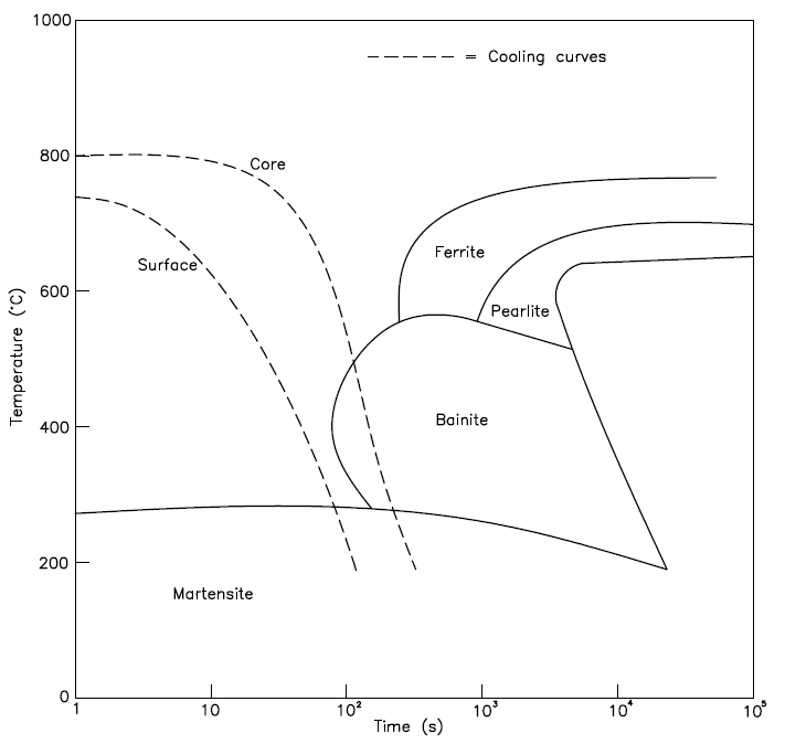
During the quenching process, heat must be transferred to the surface of the specimen before it can be dissipated into the quenching medium. Consequently, the rate at which the interior of the specimen cools is dependent on its surface area to volume ratio. The larger the ratio, the more rapid the specimen will cool and therefore the deeper the hardening effect. For example, a 3-inch cylindrical bar with a 1-inch diameter will have a higher hardenability than a 3-inch bar with a 1.5-inch diameter. Because of this effect, parts with more corners and edges are more amendable to hardening by quenching than regular and rounded shapes. Figure 2 is a sample time-temperature transformation (TTT) diagram of the cooling curves of an oil-quenched 95 mm bar. The surface will transform into 100% martensite while the core will contain some bainite and thus have a lower hardness.
Figure 2: Sample time temperature transformation (TTT) diagram also known as an isothermal transformation diagram
2. The composition of the steel
It’s important to remember that different alloys of steel
contain different elemental compositions. The ratio of these elements relative
to the amount of iron within the steel yield a wide variety of mechanical
properties. Increasing the carbon content makes steel harder and stronger but
less ductile. The predominant alloying element of stainless steels in chromium,
which gives the metal its strong resistance to corrosion. Since humans have
been tinkering with the composition of steel for over a millennium, the number
of combinations is endless.
Because there are so many combinations that yield so many
different mechanical properties, standardized tests are used to help categorize
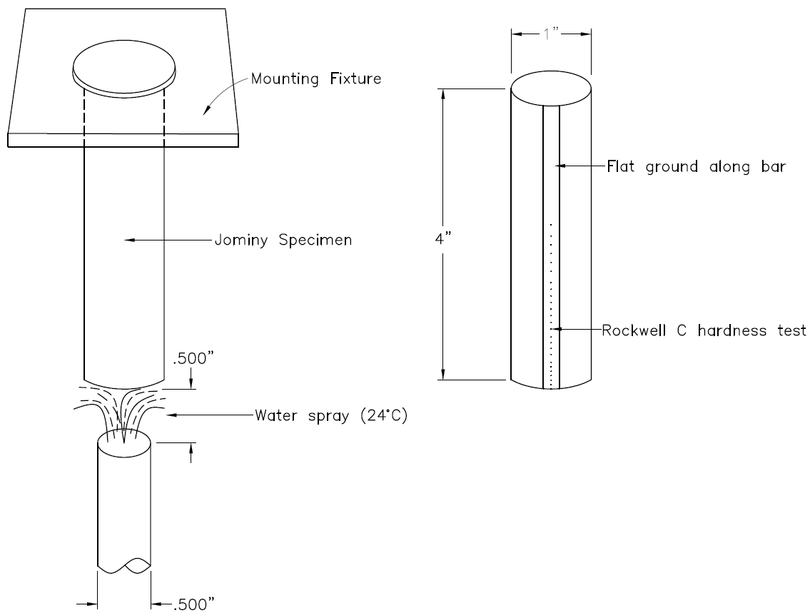
different types of steel. A common test for hardenability is the Jominy Test,
shown in Figure 3 below. During this test a standard block of material is
heated until it is 100% austenite. The block is then quickly moved to an
apparatus where it is water quenched. The surface, or the area in contact with
the water, is immediately cooled and the rate of cooling drops as a function of
distance from the surface. A flat is then ground onto the block along the length
of the sample. The hardness at various points is measured along this flat. This
data is then plotted in a hardenability chart with hardness as the y-axis and
distance as the x-axis.
Figure 3: Diagram of a Jominy end quench specimen mounted during quenching (left) and post hardness testing (right)
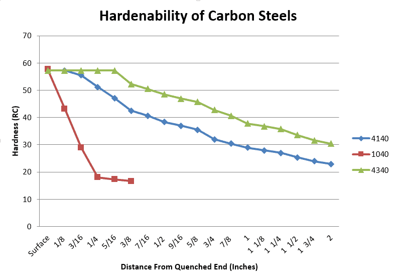
Hardenability curves are constructed from the results of Jominy Tests. Examples of a few steel alloy curves are shown in Figure 4. With a diminishing cooling rate (steeper drop in hardness over a short distance), more time is allowed for carbon diffusion and the formation of a greater proportion of softer pearlite. This means less martensite and a lower hardenability. A material that retains higher hardness values over relatively long distances is considered highly hardenable. Also, the greater the difference in hardness between the two ends, the lower the hardenability. It is typical of hardenability curves that as the distance from the quenched end increases, the cooling rate decreases. 1040 steel initially has the same hardness as both 4140 and 4340 but cools extremely quickly over the length of the sample. 4140 and 4340 steel cool at a more gradual rate and therefore have a higher hardenability. 4340 has a less extreme rate of coolness relative to 4140 and thus has the highest hardenability of the trio.
Figure 4: Hardenability charts for 4140, 1040 and 4340 steels
Hardenability curves are dependent on carbon content. A greater percentage of carbon present in steel will increase its hardness. It should be noted that all three alloys in Figure 4 contain the same amount of carbon (0.40% C). Carbon is not the only alloying element that can have an effect on hardenability. The disparity in hardenability behavior between these three steels can be explained in terms of their alloying elements. Table 1 below shows a comparison of the alloying content in each of the steels. 1040 is a plain carbon steel and therefore has the lowest hardenability as there are no other elements besides iron to block the carbon atoms from escaping the matrix. The nickel added to 4340 allows for a slightly greater amount of martensite to form compared to 4140, giving it the highest hardenability of these three alloys. Most metallic alloying elements slow down the formation of pearlite, ferrite and bainite, therefore they increase a steel’s hardenability.
Table
1: Shows the alloying contents of 4340, 4140, and 1040
steel
Type of Steel:
Nickel (wt %):
Molybdenum (wt %):
Chromium (wt %):
4340
1.85%
0.25%
0.80%
4140
0.00%
0.20%
1.00%
1040
0.00%
0.00%
0.00%
There can be a variation in hardenability within one
material group. During the industrial production of steel, there are always
slight unavoidable variations in the elemental composition and average grain
size from one batch to another. Most of the time a material’s hardenability is
represented by maximum and minimum curves set as limits.
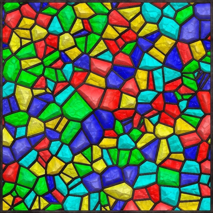
Hardenability also increases with increasing austenitic grain size. A grain is an individual crystal in a polycrystalline metal. Think of a stained glass window (like the one seen below), the colored glass would be the grains while the soldering material holding it altogether would be the grain boundaries. Austenite, ferrite, and cementite are all different types of grains that make up the different microstructures of steel. It is at the grain boundaries that the pearlite and bainite will form. This is detrimental to the hardening process as martensite is the desired microstructure, the other types get in the way of its growth. Martensite forms from the rapid cooling of austenite grains and its transformation process is still not well understood. With increasing grain size, there are more austenite grains and fewer grain boundaries. Therefore, there are fewer opportunities for microstructures like pearlite and bainite to form and more opportunities for martensite to form.
Figure 5: The colorful glass pieces represent grains of austenite which transforms into the desirable martensite upon quenching. The black portions in between the color portions represent grain boundaries. Sites where pearlite or bainite will form upon quenching.
3. The method of quenching
As previously stated, the type of quench affects the cooling
rate. Using oil, water, aqueous polymer quenchants, or air will yield a
different hardness through the interior of the workpiece. This also shifts the
hardenability curves. Water produces the most severe quench followed by oil and
then air. Aqueous polymer quenchants provide quenching rates between those of
water and oil and can be tailored to specific applications by changing the
polymer concentration and temperature. The degree of agitation also affects the
rate of heat removal. The faster the quenching medium moves across the
specimen, the greater the quenching effectiveness. Oil quenches are generally
used when a water quench may be too severe for a type of steel as it may crack
or warp upon treatment.
Figure 6: Metalworker quenching casts in an oil bath
Machining Hardened Steels
The type of cutter that should be chosen for processing tools chosen for machining a workpiece after hardening depends on a few different variables. Not counting the geometric requirements specific to the application, two of the most important variables are the material hardness and its hardenability. Some relatively high-stress applications require a minimum of 80% martensite to be produced throughout the interior of the workpiece. Usually, moderately stressed parts only require about 50% martensite throughout the workpiece. When machining a quenched metal with very low hardenability a standard coated solid carbide tool may work without a problem. This is because the hardest portion of the workpiece is limited to its surface. When machining a steel with a high hardenability it is recommended that you use a cutter with specialized geometry that is for that specific application. High hardenability will result in a workpiece that is hard throughout its entire volume. Harvey Tool has a number of different cutters for hardened steel throughout the catalog, including drills, end mills, keyseat cutters, and engravers.
Hardenability is a measure of the depth to which a ferrous alloy may be hardened by the formation of martensite throughout its entire volume, surface to core. It is an important material property you must consider when choosing a steel as well as cutting tools for a particular application. The hardening of any steel depends on the size and shape of the part, the molecular composition of the steel, and the type of quenching method used.
https://www.harveyperformance.com/wp-content/uploads/2020/04/Hardened-Steel.jpg6001599Robert Keeverhttp://www.harveyperformance.com/wp-content/uploads/2018/08/Logo_HarveyPerformanceCompany-4.pngRobert Keever2020-04-10 14:52:212024-02-12 11:23:36Hardenability of Steel
We use cookies to ensure that we give you the best experience on our website. If you continue to use this site we will assume that you are happy with it.Ok