This website www.harveyperformance.com/in-the-loupe/category/tool-selection/specialty-tools/ is currently offline. Cloudflare's Always Online™ shows a snapshot of this web page from the Internet Archive's Wayback Machine. To check for the live version, click Refresh.
Making a manual tool change on any CNC machine is never a
timely or rewarding process. Typically, a tool change in a standard holder can
take up to 5 minutes. Add that up a few times, and suddenly you have added
significant minutes to your production time.
As CNC machine tool and cutting tool technology has advanced, there are more multi-functional tools available to help you avoid tool changes. However, sometimes it just isn’t feasible, and multiple tool changes are needed. Luckily, Micro 100 has developed a revolutionary new method to speed up tool changes significantly.
What is the Micro-Quik Tooling System?
Developed in Micro 100’s world-class grinding facility in Meridian, Idaho, the Micro 100 Micro-Quik tooling systemis held to the same standards and tight tolerances as all of the Micro 100 carbide tooling.
The quick change tooling system allows for highly repeatable tool changes that save countless hours without sacrificing performance. This system combines a unique tool holder with a unique tool design to deliver highly repeatable and accurate results.
Each quick change tool holder features a locating/locking set screw to secure the tool and a locating pin which helps align the tool for repeatability. Removing a tool is as simple as loosening the set screw and inserting its replacement.
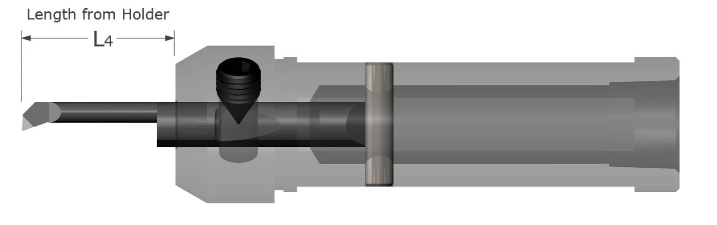
During tool changes, the precision ground bevel on the rear of the tool aligns with a locating pin inside the tool holder. The distance from this locational point to the tip of the tool is highly controlled under tight tolerances, meaning that the Micro-Quik tooling system ensures a very high degree of tool length and centerline repeatability. The “L4” dimension on all of our quick change tools, as seen in the image above, remains consistent across the entire product line. Check out the video below for a demonstration of the Micro 100 Micro-Quik system in action!
Quick Change Tooling Benefits
The most obvious benefit to using Micro 100’s Micro-Quik Quick Change Tooling System is the time savings that come with easier tool changes. By using the quick change holders in combination with quick change tooling, it is easy to reduce tool changes from 5 minutes to under 30 seconds, resulting in a 90% decrease in time spent swapping out tools. This is a significant benefit to the system, but there are benefits once the tool is in the machine as well.
As mentioned above, the distance from the locational point on each tool shank to the tip of the tool is highly controlled, meaning that regardless of which type of tool you insert into the holder, your stick out will remain the same. This allows you to have confidence in the tooling and does not require additional touch offs, which is another major time saver.
By removing additional touch-offs and tool changes from your workflow, you also reduce the chances for human or machine error. Improper touch-offs or tool change errors can cause costly machine crashes and result in serious repairs and downtime. With the Micro 100 Micro-Quik Quick Change Tooling System, initial setups become much easier, allowing you to hit the cycle start button with total confidence for each run.
By making a few simple changes to your tool holding configurations and adopting the Micro-Quik system, your shop can save thousands in time saved, with less machine downtime and increased part production. To learn more about the Micro 100 Micro-Quik cutting tools and tool holders, please visit Micro 100.
https://www.harveyperformance.com/wp-content/uploads/2020/04/Feature-Image-Quick-Change-Tooling-IMG.jpg5251400Harvey Performance Companyhttp://www.harveyperformance.com/wp-content/uploads/2018/08/Logo_HarveyPerformanceCompany-4.pngHarvey Performance Company2020-04-10 08:00:002023-10-05 08:58:22Save Time With Quick Change Tooling
A chamfer cutter, or a chamfer mill, can be found at any machine shop, assembly floor, or hobbyist’s garage. These cutters are simple tools that are used for chamfering or beveling any part in a wide variety of materials. There are many reasons to chamfer a part, ranging from fluid flow and safety, to part aesthetics.
Due to the diversity of needs, tooling manufacturers offer many different angles and sizes of chamfer cutters, and as well as different types of chamfer cutter tip geometries. Harvey Tool, for instance, offers 21 different angles per side, ranging from 15° to 80°, flute counts of 2 to 6, and shank diameters starting at 1/8” up to 1 inch.
After finding a tool with the exact angle they’re looking for, a customer may have to choose a certain chamfer cutter tip that would best suit their operation. Common types of chamfer cutter tips include pointed, flat end, and end cutting. The following three types of chamfer cutter tip styles, offered by Harvey Tool, each serve a unique purpose.
Pointed and Flat End Chamfer Cutters
Three Types of Harvey Tool Chamfer Cutters
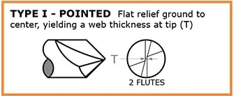
Type I: Pointed
This style of chamfer cutter is the only Harvey Tool option that comes to a sharp point. The pointed tip allows the cutter to perform in smaller grooves, slots, and holes, relative to the other two types. This style also allows for easier programming and touch-offs, since the point can be easily located. It’s due to its tip that this version of the cutter has the longest length of cut (with the tool coming to a finished point), compared to the flat end of the other types of chamfer cutters. With only a 2 flute option, this is the most straightforward version of a chamfer cutter offered by Harvey Tool.
Type II: Flat End, Non-End Cutting
Type II chamfer cutters are very similar to the type I style, but feature an end that’s ground down to a flat, non-cutting tip. This flat “tip” removes the pointed part of the chamfer, which is the weakest part of the tool. Due to this change in tool geometry, this tool is given an additional measurement for how much longer the tool would be if it came to a point. This measurement is known as “distance to theoretical sharp corner,” which helps with the programming of the tool. The advantage of the flat end of the cutter now allows for multiple flutes to exist on the tapered profile of the chamfer cutter. With more flutes, this chamfer has improved tool life and finish. The flat, non-end cutting tip flat does limit its use in narrow slots, but another advantage is a lower profile angle with better angular velocity at the tip.
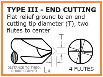
Type III: Flat End, End Cutting
Type III chamfer cutters are an improved and more advanced version of the type II style. The type III boasts a flat end tip with 2 flutes meeting at the center, creating a center cutting-capable version of the type II cutter. The center cutting geometry of this cutter makes it possible to cut with its flat tip. This cutting allows the chamfer cutter to lightly cut into the top of a part to the bottom of it, rather than leave material behind when cutting a chamfer. There are many situations where blending of a tapered wall and floor is needed, and this is where these chamfer cutters shine. The tip diameter is also held to a tight tolerance, which significantly helps with programing it.
In conclusion, there could be many suitable cutters for a single job, and there are many questions you must ask prior to picking your ideal tool. Choosing the right angle comes down to making sure that the angle on the chamfer cutter matches the angle on the part. One needs to be cautious of how the angles are called out, as well. Is the angle an “included angle” or “angle per side?” Is the angle called off of the vertical or horizontal? Next, the larger the shank diameter, the stronger the chamfer and the longer the length of cut, but now, interference with walls or fixtures need to be considered. Flute count comes down to material and finish. Softer materials tend to want less flutes for better chip evacuation, while more flutes will help with finish. After addressing each of these considerations, the correct style of chamfer for your job should be abundantly clear.
https://www.harveyperformance.com/wp-content/uploads/2017/08/Feature-Image-Uses-of-Chamfer-Mill-IMG.jpg5251400Harvey Performance Companyhttp://www.harveyperformance.com/wp-content/uploads/2018/08/Logo_HarveyPerformanceCompany-4.pngHarvey Performance Company2019-11-22 08:20:372024-02-12 13:58:50Selecting the Right Chamfer Cutter Tip Geometry
Dovetail Cutters are cutting tools that create a trapezoidal-type shape, or a dovetail groove, in a part. Due to the form of these tools, special considerations need to be made in order to achieve long tool life and superior results. This is particularly true when machining O-ring grooves, as this operation requires the tool to drop into the part to begin cutting. Using an appropriate tool entry method, specifically understanding when drop hole allowance is (and is not) needed, is important to keep common dovetail mishaps from occurring.
What is a Drop-Hole?
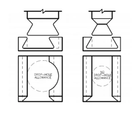
When designing parts featuring O-ring grooves, the consideration of drop-hole allowance is a pivotal first step. A drop-hole is an off-center hole milled during the roughing/slotting operation. This feature allows for a significantly larger, more rigid tool to be used. This is because the cutter no longer has to fit into the slot, but into a hole with a diameter larger than its cutter diameter.
Why consider adding a Drop-Hole?
When compared to tools without drop-hole allowance, tools with drop-hole allowance have a much larger neck diameter-to-cutter diameter ratio. This makes the drop-hole tools far stronger, permitting the tool to take heavy radial depths of cut and fewer step-overs. Using a drop-hole will allow the use of the stronger tool, which will increase production rate and improve tool life.
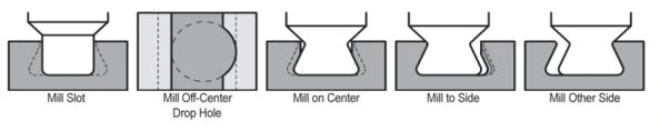
Machining Operation with Drop-Hole Allowance
A maximum of 4 radial passes per side are needed.
When Not to Drop Hole
Drop-holes are sometimes not permitted in a design due to the added stress concentration point it leaves. Common examples for where a drop-hole would not be allowed include:
In high pressure applications
In seals requiring a high reliability
Where dangerous or hazardous fluids are being used
The issue with drop-hole allowance is that the additional clearance used for tool entry can create a weak spot in the seal, which can then become compromised under certain conditions. Ultimately, drop-hole allowance requires approval from the customer to ensure the application allows for it.
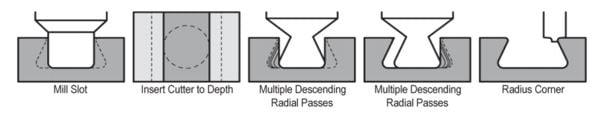
Machining Operation Without Drop-Hole Allowance
A maximum of 20 radial passes per side are needed.
Drop-Hole Placement
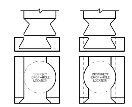
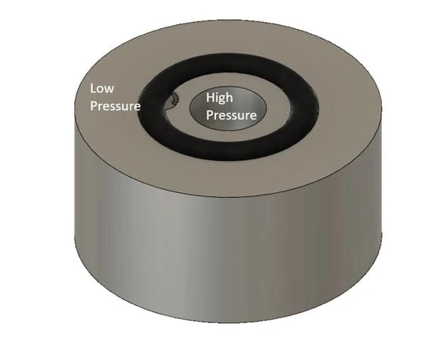
When adding a drop-hole to your part, it is important to ensure that the feature is placed correctly to maximize seal integrity. Per the below figure, the drop-hole should be placed off center of the groove, ensuring that only one side of the groove is affected.
It is also necessary to ensure that drop-hole features are put on the correct side of the groove. Since O-rings are used as a seal between pressures, it is important to have the drop-hole bordering the high pressure zone. As pressure moves from high to low, the O-ring will be forced into the fully supported side, allowing for a proper seal (See image below).
https://www.harveyperformance.com/wp-content/uploads/2019/05/Feature-Image-Drop-Hole-Allowance-IMG-1.jpg5251400Harvey Performance Companyhttp://www.harveyperformance.com/wp-content/uploads/2018/08/Logo_HarveyPerformanceCompany-4.pngHarvey Performance Company2019-05-06 09:48:552023-10-24 10:53:22When to and Not to Use Drop Hole Allowance
While similar on the surface, Half-round Engraving Cutters and Marking Cutters are actually very different. Both tools are unique in the geometries they possess, the benefits they offer, and the specific purposes they’re used for. Below are the key differences that all machinists must know, as the engraving on a part is often a critical step in the machining process.
Engravers & Marking Cutters Serve Different Purposes
All Marking Cutters are Engraving Cutters, but not all Engraving Cutters are Marking Cutters. This is because Marking Cutters are a “type” of engraving tool. By virtue of their sturdier geometry, these tools are suited for applications requiring repetition such as the engraving of serial numbers onto parts. Harvey Tool has been able to customize specific tool geometries for ferrous and non-ferrous applications, offering Marking Cutters for material specific purposes.
Engraving Cutters, on the other hand, are meant for finer detailed applications that require intricate designs such as engraving a wedding band or a complex brand design.
These Tools Have Unique Geometry Features
Historically, Engraving Cutters have been made as a half round style tool. This tool allows for a true point, which is better for fine detail, but can easily break if not run correctly. Because of this, these tools have performed well in softer materials such as aluminum and wood, especially for jobs that require an artistic engraving with fine detail.
Marking cutters are not as widely seen throughout the industry, however. These tools hold up in harder-to-machine materials exceedingly well. Marking Cutters are a form of Engraving Cutter that contain 2 flutes and a web at the tip, meaning that the tool has a stronger tip and is less susceptible to breakage.
While these tools do not contain a true point (due to their web), they do feature shear flutes for better cutting action and the ability to evacuate chips easier when compared to a half-round engraver.
Harvey Tool Product Offering
Harvey Tool offers a wide variety of both Engraving Cutters and Marking Cutters. Choose from a selection of pointed, double-ended, tip radius, and tipped-off Engraving Cutter styles in 15 included angles ranging from 10° to 120°.
Marking Cutters are fully stocked in tip radius or tipped-off options, and are designed specifically for either ferrous or non-ferrous materials. They are are offered in included angles from 20° to 120°.
While Engraving Cutters are offered uncoated or in AlTiN, AlTiN Nano, or Amorphous Diamond coatings, Marking Cutters are fully stocked in uncoated, AlTiN, or TiB2 coated styles.
While both Engraving Cutters and Marking Cutters can accomplish similar tasks, each tool has its own advantages and purpose. Selecting the correct tool is based largely on preference and applicability to the job at hand. Factors that could impact your selection would be final Depth of Cut, Width of Cut, the angle needing to be achieved, and the desired detail of the engraving.
A Corner Rounding End Mill is typically used to add a specific radius to a workpiece, or in a finishing operation to remove a sharp edge or burr. Prior to selecting your tool, mull the following considerations over. Choosing the right tool will result in a strong tool with a long usable life, and the desired dimensional qualities on your part. Choosing wrong could result in part inaccuracies and a subpar experience.
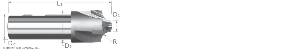
Selecting the Right Pilot Diameter for Your Corner Rounding End Mill
The pilot diameter (D1 in the image above) determines the tool’s limitations. When pilot diameters are larger, the tool is able to be run at lower speeds. But with smaller pilot diameters, the tool can be run faster because of its larger effective cutter radius. The effective cutter diameter is determined by the following equations depending on the radius to pilot ratio:
For a Radius/Pilot Ratio < 2.5, Effective Cutter Diameter = Pilot Diameter + Radius For a Radius/Pilot Ratio ≥ 2.5, Effective Cutter Diameter = Pilot Diameter + .7x Radius
Larger pilot diameters also have more strength than smaller pilot diameters due to the added material behind the radius. A smaller pilot may be necessary for clearance when working in narrow slots or holes. Smaller pilots also allow for tighter turns when machining an inside corner.
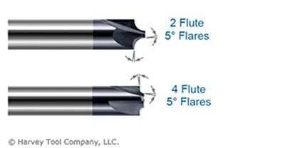
Flared or Unflared Corner Rounder
Putting a full radius on a part has the potential to leave a step or an over-cut on a workpiece. This can happen if the tool isn’t completely dialed in or if there is minor runout or vibration. A slight 5° flare on the pilot and shoulder blends the radius smoothly on the workpiece and avoids leaving an over-cut.
A flared Corner Rounding End Mill leaves an incomplete radius but allows for more forgiveness. Additionally, this tool leaves a clean surface finish and does not require a second finishing operation to clean leftover marks. An unflared corner radius leaves a complete radius on the workpiece, but requires more set-up time to make sure there is no step.
Front or Back
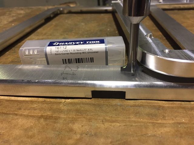
Choosing between a Corner Rounding End Mill and a Back Corner tool boils down to the location on the part you’re machining. A Back Corner Rounding End Mill should be utilized to put a radius on an area of the part facing the opposite direction as the spindle. While the material could be rotated, and a front Corner Rounding End Mill used, this adds to unnecessary time spent and increased cycle times. When using a Back Corner Rounding End Mill, ensure that you have proper clearance for the head diameter, and that the right reach length is used. If there is not enough clearance, the workpiece will need to be adjusted.
Flute Count
These tools are often offered in 2, 3, and 4 flute styles. 2 flute styles are normally used for aluminum and non-ferrous materials, although 3 flutes is quickly becoming a more popular choice for these materials, as they are softer than steels so a larger chip can be taken without an impact on tool life. 4 flutes should be chosen when machining steels to extend tool life by spreading out the wear over multiple teeth. 4 flute versions can also be run at higher feeds compared to 2 or 3 flute tools.
Corner Rounding End Mill Selection Summarized
The best corner rounding end mill varies from job-to-job. Generally speaking, opting for a tool with the largest pilot diameter possible is your best bet, as it has the most strength and requires less power due to its larger effective cutter diameter. A flared Corner Rounder is preferred for blending purposes if the workpiece is allowed to have an incomplete radius as this allows more forgiveness and can save on set up time. If not, however, an unflared Corner Rounder should be utilized. As is often the case, choosing between number of flutes boils down to user preference, largely. Softer materials usually require fewer flutes. As material gets harder, the number of flutes on your tool should increase.
Deburring is a process in which sharp edges and burrs are removed from a part to create a more aesthetically pleasing final product. After milling, parts are typically taken off the machine and sent off to the Deburring Department. Here, the burrs and sharp points are removed, traditionally by hand. However, an operation that takes an hour by hand can be reduced to mere minutes by deburring parts right in the machine with high precision CNC deburring tools, making hand deburring a thing of the past.
High Precision Tools
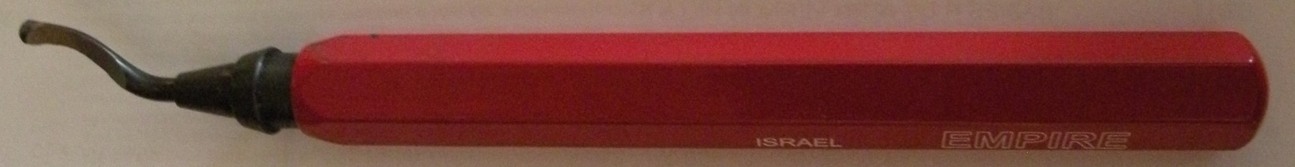
Hand deburring tools often have a sharp hook-shaped blade on the end, which is used to scrape/slice off the burrs as it passes along the edge of the part. These tools are fairly simple and easy to use, but much less efficient and precise than CNC deburring tools.
CNC deburring tools are also held to much tighter tolerances than traditional hand-deburring tools. Traditional cylindrical deburring tools typically have a diameter-tolerance window of +/- .008 versus a CNC deburring end mill which has a diameter tolerance of +/-.0005. The tighter tolerance design eliminates the location issues found in traditional deburring tools with loose tolerances, allowing them to be programmed like a traditional end mill.
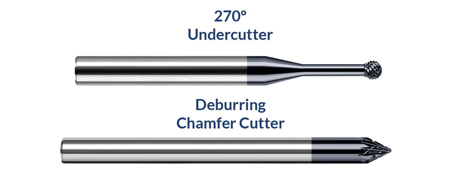
While hand deburring tools often have just a single blade, CNC deburring tools feature double cut patterns and a high number of flutes. The double cut pattern contains both right hand and left hand teeth, which results in an improved finish. These tools leave completed parts looking far superior to their hand-deburred counterparts, with more consistent and controlled edge breaks. Additionally, there is a large variety of CNC deburring tools available today which can take full advantage of multi-axis machines and the most complex tool paths. For example, Harvey Tool’s 270° Undercutting End Mill is a great choice for multi-axis and more complex deburring options. Further, Deburring Chamfer Cutters are multi-use tools that can perform both chamfering and deburring accurately with no need for a tool change.
Reduce Production Costs and Increase Profits
Having an entire department dedicated to deburring can be costly, and many smaller businesses may have pulled employees off other jobs to help with deburring, which hampers production. Taking employees off the deburring station and asking them to run more parts or man another department can help keep labor costs low while still increasing production rates.
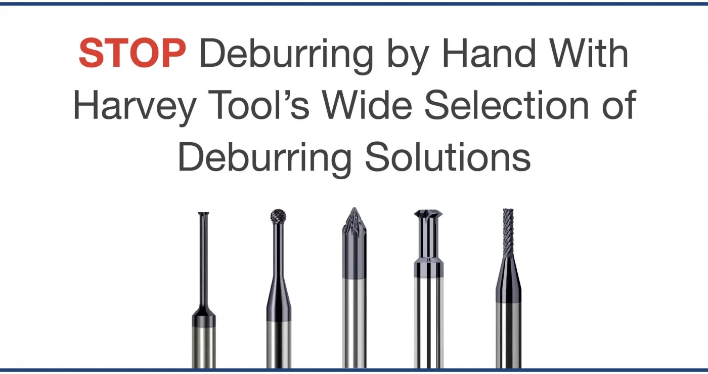
Stop Deburring By Hand and Increase Your Profits
By deburring right in the CNC machine, parts can be completed in one machining operation. The double-cut pattern found on many deburring tools also allows for increased speeds and feeds. This helps to reduce cycle times even further, saving hours of work and increasing production efficiency. Deburring in the machine is a highly repeatable process that reduces overall cycle times and allows for more efficient finishing of a part. In addition, CNC machines are going to be more accurate than manual operations, leading to fewer scrapped parts due to human error and inconsistencies.
Simply put, the precision and accuracy of the CNC machine, along with the cost and time savings associated with keeping the part in the machine from start to finish, makes deburring in the CNC machine one of the easiest way to increase your shop’s efficiency.
https://www.harveyperformance.com/wp-content/uploads/2018/03/Feature-Image-Stop-Deburring-by-Hand-IMG-1.jpg5251400Harvey Performance Companyhttp://www.harveyperformance.com/wp-content/uploads/2018/08/Logo_HarveyPerformanceCompany-4.pngHarvey Performance Company2018-03-13 16:26:182024-02-12 14:37:41Why You Should Stop Deburring by Hand
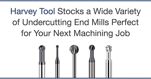
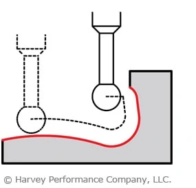
Undercutting end mills, also known as lollipop cutters or spherical ball end mills, are a common choice for machining undercuts. An undercut is a common part feature characterized by one part of a workpiece “hanging” over another. Undercuts are typically difficult, or even impossible, to machine with a standard tool, especially on 3-axis machines. In many cases, a specialty tool is needed to tackle this feature. Although they are frequently associated with a singular use, undercutters are actually very versatile tools that are worth keeping on hand for a variety of operations.
Undercutting
Unsurprisingly, these tools are very well suited to undercutting operations. Creating an undercut on a part can be tricky and time consuming, especially when forced to rotate the workpiece. Fortunately, this can be greatly simplified with an undercutter.
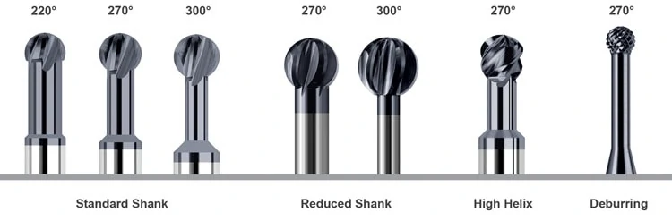
Exactly what tool to use depends on the geometry of the feature and the part. These tools are available with a range of wrap angles like 220°, 270°, and 300°. Greater wrap angles are the result of a thinner neck and create a more spherical cutting end. This style offers more clearance at the cost of rigidity. Likewise, undercutting end mills with lower wrap angles sacrifice clearance for greater rigidity.
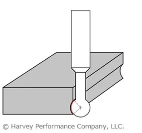
Deburring & Edgebreaking
Since undercuts have a wrap angle that is greater than 180°, they are very well-suited to deburring or edgebreaking anywhere on your workpiece, including the underside. Deburring your parts by hand can be inefficient for your shop – using an undercutting end mill instead will save you time and money. Edgebreaking operations are often a critical final step to create a part that looks and feels like a finished product and that is safe to handle.
All undercutting end mills can be used to deburr and edgebreak, which makes them a useful tool to have on hand in any shop. Some manufacturers also offer specialized deburring tools that are designed with a right and left hand flute orientation, giving them “teeth” that make them particularly useful for deburring complex shapes. Using a deburring tool in a 5-axis machine often makes it possible to deburr or edgebreak an entire workpiece in one shot.
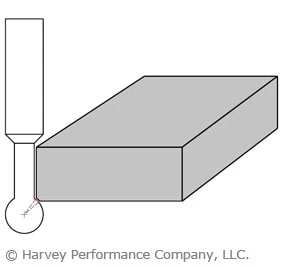
Slotting
Most machinists might not think of undercutting end mills for slotting, but they are fully capable of this operation. An equivalent slot can be machined with a regular ball end mill, but doing so might not be feasible due to clearance issues – an undercutter has a reduced neck, unlike a standard ball end mill. Additionally, using an undercutter to slot can save time switching to an equivalent ball end mill.
Since only 180° of the cutting end can be used to slot, undercutting end mills with lower wrap angles and thicker necks are best suited to slotting. However, high helix undercutting tools may be ideal if improved finish and increased chip removal are important to the operation.
Contouring & Profiling
With their wrap angle and increased clearance, undercutting end mills are very useful for both simple and complicated contouring and profiling operations. Their versatility means that it is sometimes possible to accomplish the entire operation with a single tool, rather than several, especially when 5-axis milling.
Reduced shank tools offer the most versatility in complex contouring and profiling operations. The ability to chuck these tools at any depth means that they are capable of maximum clearance.
Choosing An Undercutting End Mill
While most undercutting end mills are conceptually similar, there are a few key differences that must be considered when picking the right tool for your job. Harvey Tool offers the following styles as stock standard tools.
https://www.harveyperformance.com/wp-content/uploads/2017/08/Feature-Image-Undercutting-IMG.jpg5251400Harvey Performance Companyhttp://www.harveyperformance.com/wp-content/uploads/2018/08/Logo_HarveyPerformanceCompany-4.pngHarvey Performance Company2017-08-16 16:00:002024-02-12 14:46:18Undercutting End Mills: Well-Rounded Tools That Offer Maximum Versatility
While they are specialty tools, dovetail style cutters have a broad range of applications. Dovetails are typically used to cut O-ring grooves in fluid and pressure devices, industrial slides and detailed undercutting work. Dovetail cutters have a trapezoidal shape—like the shape of a dove’s tail. General purpose dovetails are used to undercut or deburr features in a workpiece. O-ring dovetail cutters are held to specific standards to cut a groove that is wider at the bottom than the top. This trapezoidal groove shape is designed to hold the O-ring and keep it from being displaced.
The dovetail cutter’s design makes it fragile, finicky, and highly susceptible to failure. In calculating job specifications, machinists frequently treat dovetail cutters as larger than they really are because of their design, leading to unnecessary tool breakage. They mistake the tool’s larger end diameter as the critical dimension when in fact the smaller neck diameter is more important in making machining calculations.
As the tools are downsized for micro-applications, their unique shape requires special considerations. When machinists understand the true size of the tool, however, they can minimize breakage and optimize cycle time.
Miniature Matters – Micro Dovetailing
As the trend towards miniaturization continues, more dovetailing applications arise along with the need for applying the proper technique when dovetailing microscale parts and features. However, there are several common misunderstandings about the proper use of dovetails, which can lead to increased tool breakage and less-than-optimal cycle times.
There are seven common mistakes made when dovetailing and several strategies for avoiding them:
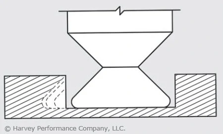
1. Not Taking Advantage of Drop Holes
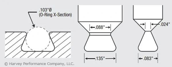
Many O-ring applications allow for a drop hole to insert the cutter into the groove. Take advantage of a drop hole if the part design allows it, as it will permit usage of the largest, most rigid tool possible, minimizing the chance of breakage (Figure 1).
Figure 1. These pictured tools are designed to mill a groove for a Parker Hannifin O-ring groove No. AS568A-102 (left). These O-rings have cross sections of 0.103″. There is a large variation in the tools’ neck diameters. The tool at right, with a neck diameter of 0.024″, is for applications without a drop hole, while the other tool, with a neck diameter of 0.088″, is for drop-hole applications. The drop-hole allowance allows application of the more rigid tool.
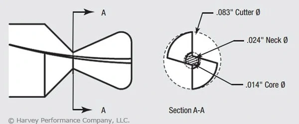
2. Misunderstanding a Dovetail’s True Neck Diameter.
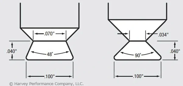
The dovetail’s profile includes a small neck diameter behind a larger end-cutting diameter. In addition, the flute runs through the neck, further reducing the tool’s core diameter. (In the example shown in Figure 2, this factor produces a core diameter of just 0.014″.) The net result is that an otherwise larger tool becomes more of a microtool. The torque generated by the larger diameter is, in effect, multiplied as it moves to the narrower neck diameter. You must remember that excess stress may be placed on the tool, leading to breakage. Furthermore, as the included angle of a dovetail increases, the neck diameter and core diameter are further reduced. O-ring dovetail cutters have an included angle of 48°. Another common included angle for general purpose dovetails is 90°. Figure 3 illustrates how two 0.100″-dia. dovetail tools have different neck diameters of 0.070″ vs. 0.034″ and different included angles of 48° vs. 90°.
Figure 2. The dovetail tool pictured is the nondrop-hole example from Figure 1. The cross section illustrates the relationship between the end diameter of the tool (0.083″) and the significantly smaller core diameter (0.014″). Understanding this relationship and the effect of torque on a small core diameter is critical to developing appropriate dovetailing operating parameters.Figure 3: These dovetail tools have the same end diameter but different neck diameters (0.070″ vs. 0.034″) and different included angles (48° vs. 90°).
3. Calculating Speeds and Feeds from the Wrong Diameter.
Machinists frequently use the wrong tool diameter to calculate feed rates for dovetail cutters, increasing breakage. In micromachining applications where the margin for error is significantly reduced, calculating the feed on the wrong diameter can cause instantaneous tool failure. Due to the angular slope of a dovetail cutter’s profile, the tool has a variable diameter. While the larger end diameter is used for speed calculations, the smaller neck diameter should be used for feed calculations. This yields a smaller chip load per tooth. For example, a 0.083″-dia. tool cutting aluminum might have a chip load of approximately 0.00065 IPT, while a 0.024″-dia. mill cutting the same material might have a 0.0002-ipt chip load. This means the smaller tool has a chip load three times smaller than the larger tool, which requires a significantly different feed calculation.
4. Errors in Considering Depth of Cut.
In micromachining applications, machinists must choose a depth of cut (DOC) that does not exceed the limits of the fragile tool. Typically, a square end mill roughs a slot and the dovetail cutter then removes the remaining triangular-shaped portion. As the dovetail is stepped over with each subsequent radial cut, the cutter’s engagement increases with each pass. A standard end mill allows for multiple passes by varying the axial DOC. However, a dovetail cutter has a fixed axial DOC, which allows changes to be made only to the radial DOC. Therefore, the size of each successive step-over must decrease to maintain a more consistent tool load and avoid tool breakage (Figure 4).
Figure 4: In microdovetailing operations, increased contact requires diminishing stepover to maintain constant tool load.
5. Failing to Climb Mill.
Although conventional milling has the benefit of gradually loading the tool, in low-chip load applications (as dictated by a dovetail cutter’s small neck diameter) the tool has a tendency to rub or push the workpiece as it enters the cut, creating chatter, deflection and premature cutting edge failure. The dovetail has a long cutting surface and tooth pressure becomes increasingly critical with each pass. Due to the low chip loads encountered in micromachining, this approach is even more critical to avoid rubbing. Although climb milling loads the tool faster than conventional milling, it allows the tool to cut more freely, providing less deflection, finer finish and longer cutting-edge life. As a result, climb milling is recommended when dovetailing.
6. Improper Chip Flushing.
Because dovetail cuts are typically made in a semi-enclosed profile, it is critical to flush chips from the cavity. In micro-dovetailing applications, chip packing and recutting due to poorly evacuated chips from a semi-enclosed profile will dull the cutter and lead to premature tool failure. In addition to cooling and lubricating, a high-pressure coolant effectively evacuates chips. However, excessive coolant pressure placed directly on the tool can cause tool vibration and deflection and even break a microtool before it touches the workpiece. Take care to provide adequate pressure to remove chips without putting undue pressure on the tool itself. Specific coolant pressure settings will depend upon the size of the groove, the tool size and the workpiece material. Also, a coolant nozzle on either side of the cutter cleans out the groove ahead of and behind the cutter. An air blast or vacuum hose could also effectively remove chips.
7. Giving the Job Away.
As discussed in item number 3, lower chip loads result in significantly lower material-removal rates, which ultimately increase cycle time. In the previous example, the chip load was three times smaller, which would increase cycle time by the same amount. Cycle time must be factored into your quote to ensure a profitable margin on the job. In addition to the important micro-dovetailing considerations discussed here, don’t forget to apply the basics critical to all tools. These include keeping runout low, using tools with application-specific coatings and ensuring setups are rigid. All of these considerations become more important in micro-applications because as tools get smaller, they become increasingly fragile, decreasing the margin of error. Understanding a dovetail cutter’s profile and calculating job specifications accordingly is critical to a successful operation. Doing so will help you reach your ultimate goal: bidding the job properly and optimizing cycle time without unnecessary breakage.
This article was written by Peter P. Jenkins of Harvey Tool Company, and it originally appeared in MicroManufacturing Magazine.
We use cookies to ensure that we give you the best experience on our website. If you continue to use this site we will assume that you are happy with it.Ok