This website www.harveyperformance.com/in-the-loupe/tag/corner-radius/ is currently offline. Cloudflare's Always Online™ shows a snapshot of this web page from the Internet Archive's Wayback Machine. To check for the live version, click Refresh.
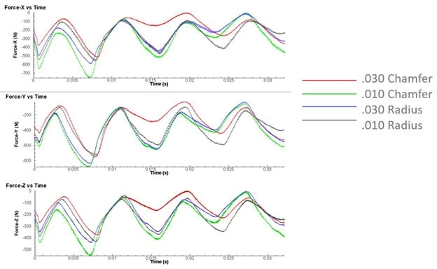
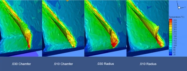
Using Finite Element Analysis (FEA) simulations by Third Wave Systems’ AdvantEdge CAE product, we tested different end mill corner geometries to compare their effects on both the tool and the workpiece. We studied and compared four 4 flute tools with either a 0.010” or 0.030” radius or chamfer. All tools were tested in 304 stainless steel at 1865 RPM, 244 SFM, and 0.0045 IPT for one revolution.
Both Corner Radius and Corner Chamfer tools offer advantages over Square End Mills by improving tool strength and reducing wear, though their benefits vary. One drawback of corner radius end mills is chip thinning along the radius, which can generate excess heat due to changes in chip thickness. This can lead to premature tool wear, poor surface finish, and potential work hardening. On the other hand, Corner Chamfers have the disadvantage of sharp corners where the chamfer meets the outer diameter (OD) and the end of the tool, causing local stress concentrations.
Force Analysis
The graphs above demonstrate the force exerted on the tool during cutting and how the corner size impacts the required force. As each flute engages, the forces peak in each direction. The 0.010” Chamfer generates the greatest force, while the 0.030” Chamfer requires the least. The forces with the radiused tools are very similar and fall between those of the two chamfered tools.
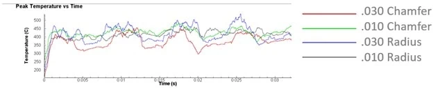
Temperature Analysis
The peak tool temperature graph shows the impact of chip thinning on corner radius tools and the overall corner size. The 0.030” Radius generated the most heat, while the 0.030” Chamfer generated the least. The temperature differences between the 0.010” Chamfer and 0.010” Radius was minimal, with the 0.010” Radius generated slightly less heat.
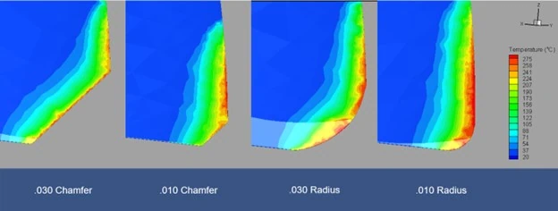
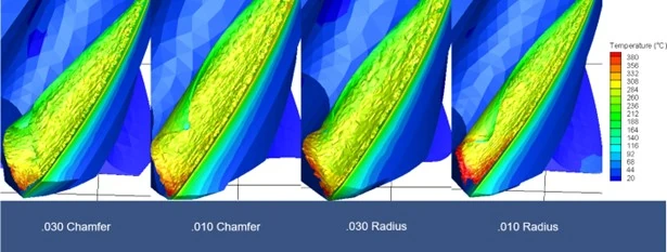
Chip and Workpiece Temperature
Understanding the temperature of the chip and workpiece is crucial for assessing tool performance. The contours above illustrate that the most heat is generated along the 0.030” Radius, followed by the 0.010” Radius. Corner Chamfer tools performed better, maintaining a lower overall temperature due to the absence of chip thinning.
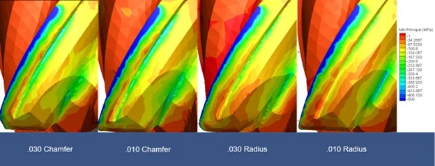
Stress Analysis
The minimum principal stress on the backside of the flute indicates areas prone to tool failure. While there were slight differences between the chamfers and radii, the most notable finding was the reduction in stress with increased corner break size.
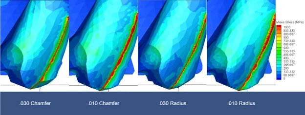
Similarly, the Mises stress analysis shows where stress is concentrated within the tool, potentially leading to failure. Again, the most significant observation was the reduction in stress with larger corner breaks.
Corner Chamfer vs. Corner Radius: Wrapped Up
Considering all factors, the 0.030” Corner Chamfer proved to be the best overall tool for 304 stainless steel. This is partly due to 304’s tendency to work harden, making excess heat generation particularly detrimental. When working with heat-sensitive materials, Corner Chamfer tools are preferable, especially during roughing, as they generate less heat due to the absence of chip thinning. Although there are minor stress concentrations at the sharp corners of Corner Chamfer tools, these are outweighed by the benefits of reduced heat generation. Larger radii exacerbate chip thinning’s impact on heat generation. While both tool styles offer advantages over square end mills, Corner Chamfer tools are more beneficial in high-heat applications where work hardening and tool wear are concerns.
Harvey Tool offers a range of Corner Chamfer Tools, with sizes ranging from 0.047” to 0.500” and various chamfer sizes to suit different applications.
A chamfer cutter, or a chamfer mill, can be found at any machine shop, assembly floor, or hobbyist’s garage. These cutters are simple tools that are used for chamfering or beveling any part in a wide variety of materials. There are many reasons to chamfer a part, ranging from fluid flow and safety, to part aesthetics.
Due to the diversity of needs, tooling manufacturers offer many different angles and sizes of chamfer cutters, and as well as different types of chamfer cutter tip geometries. Harvey Tool, for instance, offers 21 different angles per side, ranging from 15° to 80°, flute counts of 2 to 6, and shank diameters starting at 1/8” up to 1 inch.
After finding a tool with the exact angle they’re looking for, a customer may have to choose a certain chamfer cutter tip that would best suit their operation. Common types of chamfer cutter tips include pointed, flat end, and end cutting. The following three types of chamfer cutter tip styles, offered by Harvey Tool, each serve a unique purpose.
Pointed and Flat End Chamfer Cutters
Three Types of Harvey Tool Chamfer Cutters
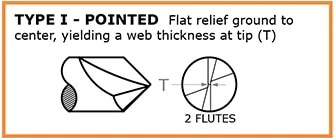
Type I: Pointed
This style of chamfer cutter is the only Harvey Tool option that comes to a sharp point. The pointed tip allows the cutter to perform in smaller grooves, slots, and holes, relative to the other two types. This style also allows for easier programming and touch-offs, since the point can be easily located. It’s due to its tip that this version of the cutter has the longest length of cut (with the tool coming to a finished point), compared to the flat end of the other types of chamfer cutters. With only a 2 flute option, this is the most straightforward version of a chamfer cutter offered by Harvey Tool.
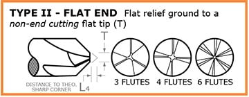
Type II: Flat End, Non-End Cutting
Type II chamfer cutters are very similar to the type I style, but feature an end that’s ground down to a flat, non-cutting tip. This flat “tip” removes the pointed part of the chamfer, which is the weakest part of the tool. Due to this change in tool geometry, this tool is given an additional measurement for how much longer the tool would be if it came to a point. This measurement is known as “distance to theoretical sharp corner,” which helps with the programming of the tool. The advantage of the flat end of the cutter now allows for multiple flutes to exist on the tapered profile of the chamfer cutter. With more flutes, this chamfer has improved tool life and finish. The flat, non-end cutting tip flat does limit its use in narrow slots, but another advantage is a lower profile angle with better angular velocity at the tip.
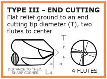
Type III: Flat End, End Cutting
Type III chamfer cutters are an improved and more advanced version of the type II style. The type III boasts a flat end tip with 2 flutes meeting at the center, creating a center cutting-capable version of the type II cutter. The center cutting geometry of this cutter makes it possible to cut with its flat tip. This cutting allows the chamfer cutter to lightly cut into the top of a part to the bottom of it, rather than leave material behind when cutting a chamfer. There are many situations where blending of a tapered wall and floor is needed, and this is where these chamfer cutters shine. The tip diameter is also held to a tight tolerance, which significantly helps with programing it.
In conclusion, there could be many suitable cutters for a single job, and there are many questions you must ask prior to picking your ideal tool. Choosing the right angle comes down to making sure that the angle on the chamfer cutter matches the angle on the part. One needs to be cautious of how the angles are called out, as well. Is the angle an “included angle” or “angle per side?” Is the angle called off of the vertical or horizontal? Next, the larger the shank diameter, the stronger the chamfer and the longer the length of cut, but now, interference with walls or fixtures need to be considered. Flute count comes down to material and finish. Softer materials tend to want less flutes for better chip evacuation, while more flutes will help with finish. After addressing each of these considerations, the correct style of chamfer for your job should be abundantly clear.
https://www.harveyperformance.com/wp-content/uploads/2017/08/Feature-Image-Uses-of-Chamfer-Mill-IMG.jpg5251400Harvey Performance Companyhttp://www.harveyperformance.com/wp-content/uploads/2018/08/Logo_HarveyPerformanceCompany-4.pngHarvey Performance Company2019-11-22 08:20:372024-02-12 13:58:50Selecting the Right Chamfer Cutter Tip Geometry
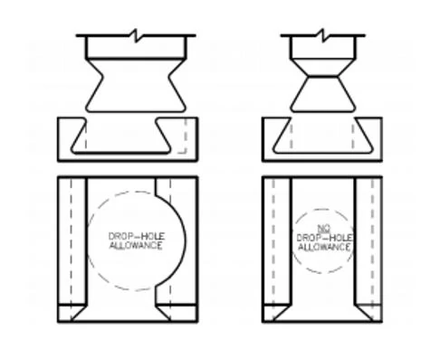
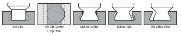
Dovetail Cutters are cutting tools that create a trapezoidal-type shape, or a dovetail groove, in a part. Due to the form of these tools, special considerations need to be made in order to achieve long tool life and superior results. This is particularly true when machining O-ring grooves, as this operation requires the tool to drop into the part to begin cutting. Using an appropriate tool entry method, specifically understanding when drop hole allowance is (and is not) needed, is important to keep common dovetail mishaps from occurring.
What is a Drop-Hole?
When designing parts featuring O-ring grooves, the consideration of drop-hole allowance is a pivotal first step. A drop-hole is an off-center hole milled during the roughing/slotting operation. This feature allows for a significantly larger, more rigid tool to be used. This is because the cutter no longer has to fit into the slot, but into a hole with a diameter larger than its cutter diameter.
Why consider adding a Drop-Hole?
When compared to tools without drop-hole allowance, tools with drop-hole allowance have a much larger neck diameter-to-cutter diameter ratio. This makes the drop-hole tools far stronger, permitting the tool to take heavy radial depths of cut and fewer step-overs. Using a drop-hole will allow the use of the stronger tool, which will increase production rate and improve tool life.
Machining Operation with Drop-Hole Allowance
A maximum of 4 radial passes per side are needed.
When Not to Drop Hole
Drop-holes are sometimes not permitted in a design due to the added stress concentration point it leaves. Common examples for where a drop-hole would not be allowed include:
In high pressure applications
In seals requiring a high reliability
Where dangerous or hazardous fluids are being used
The issue with drop-hole allowance is that the additional clearance used for tool entry can create a weak spot in the seal, which can then become compromised under certain conditions. Ultimately, drop-hole allowance requires approval from the customer to ensure the application allows for it.
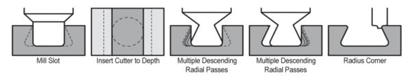
Machining Operation Without Drop-Hole Allowance
A maximum of 20 radial passes per side are needed.
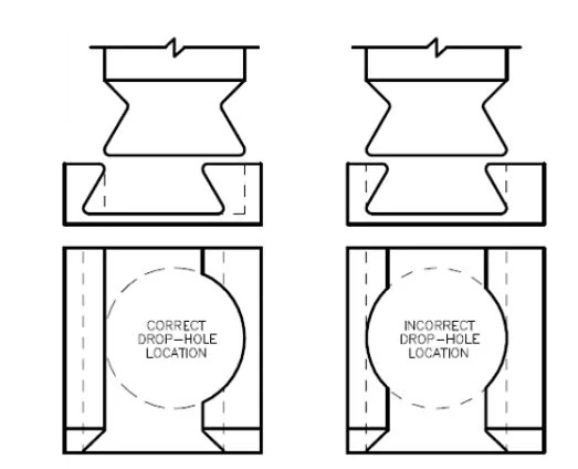
Drop-Hole Placement
When adding a drop-hole to your part, it is important to ensure that the feature is placed correctly to maximize seal integrity. Per the below figure, the drop-hole should be placed off center of the groove, ensuring that only one side of the groove is affected.
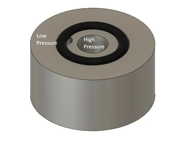
It is also necessary to ensure that drop-hole features are put on the correct side of the groove. Since O-rings are used as a seal between pressures, it is important to have the drop-hole bordering the high pressure zone. As pressure moves from high to low, the O-ring will be forced into the fully supported side, allowing for a proper seal (See image below).
https://www.harveyperformance.com/wp-content/uploads/2019/05/Feature-Image-Drop-Hole-Allowance-IMG-1.jpg5251400Harvey Performance Companyhttp://www.harveyperformance.com/wp-content/uploads/2018/08/Logo_HarveyPerformanceCompany-4.pngHarvey Performance Company2019-05-06 09:48:552023-10-24 10:53:22When to and Not to Use Drop Hole Allowance
Few steps in the machining process are as important as proper end mill selection. Complicating the process is the fact that each individual tool has its own unique geometries, each pivotal to the eventual outcome of your part. We recommend asking yourself 5 key questions before beginning the tool selection process. In doing so, you can ensure that you are doing your due diligence in selecting the best tool for your application. Taking the extra time to ensure that you’re selecting the optimal tool will reduce cycle time, increase tool life, and produce a higher quality product.
Question 1: What Material Am I Cutting?
Knowing the material you are working with and its properties will help narrow down your end mill selection considerably. Each material has a distinct set of mechanical properties that give it unique characteristics when machining. For instance, plastic materials require a different machining strategy – and different tooling geometries – than steels do. Choosing a tool with geometries tailored towards those unique characteristics will help to improve tool performance and longevity.
Helical Solutions also provides a diverse product offering tailored to specific materials, including Aluminum Alloys & Non-Ferrous Materials; and Steels, High-Temp Alloys, & Titanium. Each section includes a wide variety of flute counts – from 2 flute end mills to Multi-Flute Finishers, and with many different profiles, coating options, and geometries.
Question 2: Which Operations Will I Be Performing?
An application can require one or many operations. Common machining operations include:
Traditional Roughing
Slotting
Finishing
Contouring
Plunging
High Efficiency Milling
By understanding the operations(s) needed for a job, a machinist will have a better understanding of the tooling that will be needed. For instance, if the job includes traditional roughing and slotting, selecting a Helical Solutions Chipbreaker Rougher to hog out a greater deal of material would be a better choice than a Finisher with many flutes.
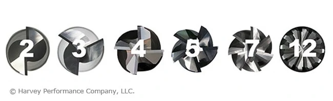
Question 3: How Many Flutes Do I Need?
One of the most significant considerations during end mill selection is determining proper flute count. Both the material and application play an important role in this decision.
Material:
When working in Non-Ferrous Materials, the most common options are the 2 or 3-flute tools. Traditionally, the 2-flute option has been the desired choice because it allows for excellent chip clearance. However, the 3-flute option has proven success in finishing and High Efficiency Milling applications, because the higher flute count will have more contact points with the material.
Ferrous Materials can be machined using anywhere from 3 to 14-flutes, depending on the operation being performed.
Application:
Traditional Roughing: When roughing, a large amount of material must pass through the tool’s flute valleys en route to being evacuated. Because of this, a low number of flutes – and larger flute valleys – are recommend. Tools with 3, 4, or 5 flutes are commonly used for traditional roughing.
Slotting: A 4-flute option is the best choice, as the lower flute count results in larger flute valleys and more efficient chip evacuation.
Finishing: When finishing in a ferrous material, a high flute count is recommended for best results. Finishing End Mills include anywhere from 5-to-14 flutes. The proper tool depends on how much material remains to be removed from a part.
High Efficiency Milling: HEM is a style of roughing that can be very effective and result in significant time savings for machine shops. When machining an HEM toolpath, opt for 5 to 7-flutes.
Question 4: What Specific Tool Dimensions are Needed?
After specifying the material you are working in, the operation(s) that are going to be performed, and the number of flutes required, the next step is making sure that your end mill selection has the correct dimensions for the job. Examples of key considerations include cutter diameter, length of cut, reach, and profile.
Cutter Diameter
The cutter diameter is the dimension that will define the width of a slot, formed by the cutting edges of the tool as it rotates. Selecting a cutter diameter that is the wrong size – either too large or small – can lead to the job not being completed successfully or a final part not being to specifications. For example, smaller cutter diameters offer more clearance within tight pockets, while larger tools provide increased rigidity in high volume jobs.
Length of Cut & Reach
The length of cut needed for any end mill should be dictated by the longest contact length during an operation. This should be only as long as needed, and no longer. Selecting the shortest tool possible will result in minimized overhang, a more rigid setup, and reduced chatter. As a rule of thumb, if an application calls for cutting at a depth greater than 5x the tool diameter, it may be optimal to explore necked reach options as a substitute to a long length of cut.
Tool Profile
The most common profile styles for end mills are square, corner radius, and ball. The square profile on an end mill has flutes with sharp corners that are squared off at 90°. A corner radius profile replaces the fragile sharp corner with a radius, adding strength and helping to prevent chipping while prolonging tool life. Finally, a ball profile features flutes with no flat bottom, and is rounded off at the end creating a “ball nose” at the tip of the tool. This is the strongest end mill style. A fully rounded cutting edge has no corner, removing the mostly likely failure point from the tool, contrary to a sharp edge on a square profile end mill. An end mill profile is often chosen by part requirements, such as square corners within a pocket, requiring a square end mill. When possible, opt for a tool with the largest corner radius allowable by your part requirements. We recommend a corner radii whenever your application allows for it. If square corners are absolutely required, consider roughing with a corner radius tool and finishing with the square profile tool.
Question 5: Should I Use a Coated Tool?
When used in the correct application, a coated tool will help to boost performance by providing the following benefits:
More Aggressive Running Parameters
Prolonged Tool life
Improved Chip Evacuation
Harvey Tool and Helical Solutions offer many different coatings, each with their own set of benefits. Coatings for ferrous materials, such as AlTiN Nano or TPlus, typically have a high max working temperature, making them suitable for materials with a low thermal conductivity. Coatings for non-ferrous applications, such as TiB2 or ZPlus, have a low coefficient of friction, allowing for easier machining operations. Other coatings, such as Amorphous Diamond or CVD Diamond Coatings, are best used in abrasive materials because of their high hardness rating.
Ready to Decide on an End Mill
There are many factors that should be considered while looking for the optimal tooling for the job, but asking the aforementioned five key question during the process will help you to make the right decision. As always, The Harvey Performance Company Technical Service Department is always available to provide recommendations and walk you through the tool selection process, if need be.
https://www.harveyperformance.com/wp-content/uploads/2018/10/Feature-Image-5-Questions-IMG-2.jpg5251400Harvey Performance Companyhttp://www.harveyperformance.com/wp-content/uploads/2018/08/Logo_HarveyPerformanceCompany-4.pngHarvey Performance Company2018-10-16 09:00:242023-10-24 10:42:255 Questions to Ask Before Selecting an End Mill
Keyseat Cutters, also known as Woodruff Cutters, Keyway Cutters, and T-Slot Cutters, are commonly used in machine shops. Many machinists opt to use this tool to put a slot on the side of a part in an efficient manner, rather than rotating the workpiece and using a traditional end mill. A Staggered Tooth Keyseat Cutter has alternating right-hand and left hand shear flutes and is right-hand cut, whereas a traditional keyseat cutter has all straight flutes and is right-hand cut. Simply, the unique geometry of a Staggered Tooth Keyseat Cutter gives the tool its own set of advantages including the ability to index within the slot, increase feed rates, and achieve better part finish.
Three Key Benefits
Indexing
The alternating right-and-left-hand flutes of a Harvey Tool Staggered Tooth Keyseat Cutters are relieved on both sides of its head, meaning that it allows for both end cutting and back cutting. This adds to the versatility of the staggered tooth keyseat cutter, where one singular tool can be indexed axially within a slot to expand the slot to a specific uncommon dimension. This can save space in a machinist’s magazine and reduce machine time by eliminating the need to swap to a new tool.
Increased Feed Rates
Due to the unique geometry of a Staggered Tooth Keyseat Cutter, chips evacuate efficiently and at a faster rate than that of a Straight Flute Keyseat Cutter. The unique flutes of Staggered Tooth Keyseat Cutters are a combination of right-and-left-hand shear flutes, but both types are right-hand cutting. This results in the tool’s teeth alternating between upcut and downcut. Chip packing and chip recutting is less of a concern with running this tool, and results in increased chip loads compared to that of a standard keyseat with the same number of flutes. Because of this, the tool can account for chiploads of about 10% higher than the norm, resulting in heightened feed rates and shorter cycle times overall.
Better Part Finish
Staggered Tooth Keyseat Cutters have “teeth”, or flutes, that are ground at an angle creating a shear flute geometry. This geometry minimizes chip recutting, chip dragging and reduces the force needed to cut into the material. Chip recutting and dragging are minimized because chips are evacuated out of the top and bottom of the head on the side of the cutter that is not engaged in the material. Shear flutes also reduce vibrations that can lead to chatter and poor finish. By minimizing cutting forces, vibration, and chatter, a machinist can expect a better part finish.
Image courtesy of @edc_machining
Staggered Tooth Keyseat Cutter Diverse Product Offering
On top of the higher performance one will experience when using the Stagger Tooth Keyseats, there are also multiple options available with various combinations to suit multiple machining needs. This style is offered in a square, square reduced shank and corner radius profile which helps if a fillet or sharp corner is needed. The square and corner radius tools are offered in diameters ranging from 1/8” to 5/8”, and the square reduced shank tool is offered in diameteres ranging from 3/4″ to 1-1/2″. The increased diameter comes with an increase of radial depth of cut, allowing deeper slots to be achievable. Within the most popular cutter diameters, ¼”, 3/8”, and ½” there are also deep slotting options with even greater radial depth of cuts for increased slot depths. On top of the diameters and radii, there are also multiple cutter widths to choose from to create different slots in one go. Finally, an uncoated and AlTiN coatings are available to further increase tool life and performance depending on the material that is being cut.
Opt for a Smoother Operation
A Staggered Tooth Keyseat Cutter adds versatility to a tool magazine. It can be indexed axially to expand slots to make multiple widths, allowing machinists to progress operations in a more efficient manner where tool changes are not required. Further, this tool will help to reduce harmonics and chatter, as well as minimize recutting. This works to create a smoother operation with less force on the cutter, resulting in a better finish compared to a Standard Keyseat Cutter.
Tolerance stacking, also known as tolerance stack-up, refers to the combination of various part dimension tolerances. After a tolerance is identified on the dimension of a part, it is important to test whether that tolerance would work with the tool’s tolerances: either the upper end or lower end. A part or assembly can be subject to inaccuracies when its tolerances are stacked up incorrectly.
The Importance of Tolerances
Tolerances directly influence the cost and performance of a product. Tighter tolerances make a machined part more difficult to manufacture and therefore often more expensive. With this in mind, it is important to find a balance between manufacturability of the part, its functionality, and its cost.
Tips for Successful Tolerance Stacking
Avoid Using Tolerances That are Unnecessarily Small
As stated above, tighter tolerances lead to a higher manufacturing cost as the part is more difficult to make. This higher cost is often due to the increased amount of scrapped parts that can occur when dimensions are found to be out of tolerance. The cost of high quality tool holders and tooling with tighter tolerances can also be an added expense.
Additionally, unnecessarily small tolerances will lead to longer manufacturing times, as more work goes in to ensure that the part meets strict criteria during machining, and after machining in the inspection process.
Be Careful Not to Over Dimension a Part
When an upper and lower tolerance is labeled on every feature of a part, over-dimensioning can become a problem. For example, a corner radius end mill with a right and left corner radii might have a tolerance of +/- .001”, and the flat between them has a .002” tolerance. In this case, the tolerance window for the cutter diameter would be +/- .004”, but is oftentimes miscalculated during part dimensioning. Further, placing a tolerance on this callout would cause it to be over dimensioned, and thus the reference dimension “REF” must be left to take the tolerance’s place.
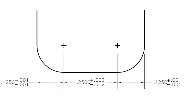
Figure 1: Shape of slot created by a corner radius end mill
Utilize Statistical Tolerance Analysis:
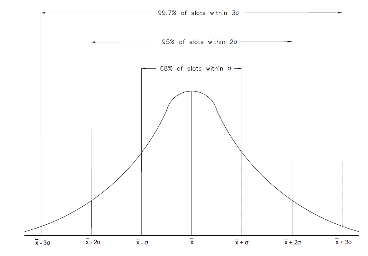
Statistical analysis looks at the likelihood that all three tolerances would be below or above the dimensioned slot width, based on a standard deviation. This probability is represented by a normal probability density function, which can be seen in figure 2 below. By combining all the probabilities of the different parts and dimensions in a design, we can determine the probability that a part will have a problem, or fail altogether, based on the dimensions and tolerance of the parts. Generally this method of analysis is only used for assemblies with four or more tolerances.
Figure 2: Tolerance Stacking: Normal distribution
Before starting a statistical tolerance analysis, you must calculate or choose a tolerance distribution factor. The standard distribution is 3 . This means that most of the data (or in this case tolerances) will be within 3 standard deviations of the mean. The standard deviations of all the tolerances must be divided by this tolerance distribution factor to normalize them from a distribution of 3 to a distribution of 1 . Once this has been done, the root sum squared can be taken to find the standard deviation of the assembly.
Think of it like a cup of coffee being made with 3 different sized beans. In order to make a delicious cup of joe, you must first grind down all of the beans to the same size so they can be added to the coffee filter. In this case, the beans are the standard deviations, the grinder is the tolerance distribution factor, and the coffee filter is the root sum squared equation. This is necessary because some tolerances may have different distribution factors based on the tightness of the tolerance range.
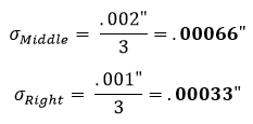
The statistical analysis method is used if there is a requirement that the slot must be .500” wide with a +/- .003” tolerance, but there is no need for the radii (.125”) and the flat (.250”) to be exact as long as they fit within the slot. In this example, we have 3 bilateral tolerances with their standard deviations already available. Since they are bilateral, the standard deviation from the mean would simply be whatever the + or – tolerance value is. For the outside radii, this would be .001” and for the middle flat region this would be .002”.
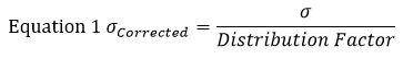
For this example, let’s find the standard deviation (σ) of each section using equation 1. In this equation represents the standard deviation.
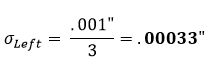
The standard assumption is that a part tolerance represents a +/- 3 normal distribution. Therefore, the distribution factor will be 3. Using equation 1 on the left section of figure 1, we find that its corrected standard deviation equates to:
This is then repeated for the middle and right sections:
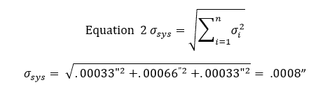
After arriving at these standard deviations, we input the results into equation 2 to find the standard deviation of the tolerance zone. Equation 2 is known as the root sum squared equation.
At this point, it means that 68% of the slots will be within a +/- .0008” tolerance. Multiplying this tolerance by 2 will result in a 95% confidence window, where multiplying it by 3 will result in a 99% confidence window.
68% of the slots will be within +/- .0008”
95% of the slots will be within +/- .0016”
99% of the slots will be within +/- .0024”
These confidence windows are standard for a normal distributed set of data points. A standard normal distribution can be seen in Figure 2 above.
Statistical tolerance analysis should only be used for assemblies with greater than 4 toleranced parts. A lot of factors were unaccounted for in this simple analysis. This example was for 3 bilateral dimensions whose tolerances were representative of their standard deviations from their means. In standard statistical tolerance analysis, other variables come into play such as angles, runout, and parallelism, which require correction factors.
Did You Know that Harvey Performance Company Brands Partner With the Industry’s Premier Cam Software Providers to Deliver Tooling Libraries?
Worst case analysis is the practice of adding up all the tolerances of a part to find the total part tolerance. When performing this type of analysis, each tolerance is set to its largest or smallest limit in its respective range. This total tolerance can then be compared to the performance limits of the part to make sure the assembly is designed properly. This is typically used for only 1 dimension (Only 1 plane, therefore no angles involved) and for assemblies with a small number of parts.
Worst case analysis can also be used when choosing the appropriate cutting tool for your job, as the tool’s tolerance can be added to the parts tolerance for a worst case scenario. Once this scenario is identified, the machinist or engineer can make the appropriate adjustments to keep the part within the dimensions specified on the print. It should be noted that the worst case scenario rarely ever occurs in actual production. While these analyses can be expensive for manufacturing, it provides peace of mind to machinists by guaranteeing that all assemblies will function properly. Often this method requires tight tolerances because the total stack up at maximum conditions is the primary feature used in design. Tighter tolerances intensify manufacturing costs due to the increased amount of scraping, production time for inspection, and cost of tooling used on these parts.
Example of worst case scenario in context to Figure 1:
Find the lower specification limit.
For the left corner radius
.125” – .001” = .124”
For the flat section
.250” – .002” = .248”
For the right corner radius
.125” – .001” = .124”
Add all of these together to the lower specification limit:
.124” + .248” + .124” = .496”
Find the upper specification limit:
For the left corner radius
.125” + .001” = .126”
For the flat section
.250” + .002” = .252”
For the right corner radius
.125” + .001” = .126”
Add all of these together to the lower specification limit:
.126” + .252” + .126” = .504”
Subtract the two and divide this answer by two to get the worst case tolerance:
(Upper Limit – Lower Limit)/2 = .004”
Therefore the worst case scenario of this slot is .500” +/- .004”.
https://www.harveyperformance.com/wp-content/uploads/2018/08/Featured-Image-Tolerance-Stacking-IMG.jpg5251400Robert Keeverhttp://www.harveyperformance.com/wp-content/uploads/2018/08/Logo_HarveyPerformanceCompany-4.pngRobert Keever2018-08-10 08:35:112024-02-12 10:41:22Best Practices of Tolerance Stacking
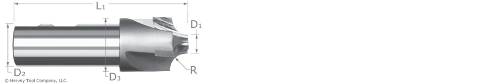
A Corner Rounding End Mill is typically used to add a specific radius to a workpiece, or in a finishing operation to remove a sharp edge or burr. Prior to selecting your tool, mull the following considerations over. Choosing the right tool will result in a strong tool with a long usable life, and the desired dimensional qualities on your part. Choosing wrong could result in part inaccuracies and a subpar experience.
Selecting the Right Pilot Diameter for Your Corner Rounding End Mill
The pilot diameter (D1 in the image above) determines the tool’s limitations. When pilot diameters are larger, the tool is able to be run at lower speeds. But with smaller pilot diameters, the tool can be run faster because of its larger effective cutter radius. The effective cutter diameter is determined by the following equations depending on the radius to pilot ratio:
For a Radius/Pilot Ratio < 2.5, Effective Cutter Diameter = Pilot Diameter + Radius For a Radius/Pilot Ratio ≥ 2.5, Effective Cutter Diameter = Pilot Diameter + .7x Radius
Larger pilot diameters also have more strength than smaller pilot diameters due to the added material behind the radius. A smaller pilot may be necessary for clearance when working in narrow slots or holes. Smaller pilots also allow for tighter turns when machining an inside corner.
Flared or Unflared Corner Rounder
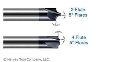
Putting a full radius on a part has the potential to leave a step or an over-cut on a workpiece. This can happen if the tool isn’t completely dialed in or if there is minor runout or vibration. A slight 5° flare on the pilot and shoulder blends the radius smoothly on the workpiece and avoids leaving an over-cut.
A flared Corner Rounding End Mill leaves an incomplete radius but allows for more forgiveness. Additionally, this tool leaves a clean surface finish and does not require a second finishing operation to clean leftover marks. An unflared corner radius leaves a complete radius on the workpiece, but requires more set-up time to make sure there is no step.
Front or Back
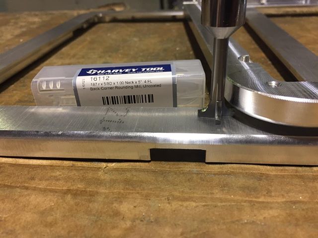
Choosing between a Corner Rounding End Mill and a Back Corner tool boils down to the location on the part you’re machining. A Back Corner Rounding End Mill should be utilized to put a radius on an area of the part facing the opposite direction as the spindle. While the material could be rotated, and a front Corner Rounding End Mill used, this adds to unnecessary time spent and increased cycle times. When using a Back Corner Rounding End Mill, ensure that you have proper clearance for the head diameter, and that the right reach length is used. If there is not enough clearance, the workpiece will need to be adjusted.
Flute Count
These tools are often offered in 2, 3, and 4 flute styles. 2 flute styles are normally used for aluminum and non-ferrous materials, although 3 flutes is quickly becoming a more popular choice for these materials, as they are softer than steels so a larger chip can be taken without an impact on tool life. 4 flutes should be chosen when machining steels to extend tool life by spreading out the wear over multiple teeth. 4 flute versions can also be run at higher feeds compared to 2 or 3 flute tools.
Corner Rounding End Mill Selection Summarized
The best corner rounding end mill varies from job-to-job. Generally speaking, opting for a tool with the largest pilot diameter possible is your best bet, as it has the most strength and requires less power due to its larger effective cutter diameter. A flared Corner Rounder is preferred for blending purposes if the workpiece is allowed to have an incomplete radius as this allows more forgiveness and can save on set up time. If not, however, an unflared Corner Rounder should be utilized. As is often the case, choosing between number of flutes boils down to user preference, largely. Softer materials usually require fewer flutes. As material gets harder, the number of flutes on your tool should increase.
As the manufacturing industry has developed, so too have the capabilities of machining centers. CNC Machines are constantly being improved and optimized to better handle the requirements of new applications. Perhaps the most important way these machines have improved over time is in the multiple axes of direction they can move, as well as orientation. For instance, a traditional 3-axis machine allows for movement and cutting in three directions, while a 2.5-axis machine can move in three directions but only cut in two. The possible number of axes for a multiaxis machine varies from 4 to 9, depending on the situation. This is assuming that no additional sub-systems are installed to the setup that would provide additional movement. The configuration of a multiaxis machine is dependent on the customer’s operation and the machine manufacturer.
Multiaxis Machining
With this continuous innovation has come the popularity of multiaxis machines – or CNC machines that can perform more than three axes of movement (greater than just the three linear axes X, Y, and Z). Additional axes usually include three rotary axes, as well as movement abilities of the table holding the part or spindle in place. Machines today can move up to 9 axes of direction.
Allowing for highly complex parts to be made in a single setup, saving time and cost.
9-Axis Machine Centers
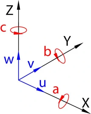
The basic 9-axis naming convention consists of three sets of three axes.
Set One
The first set is the X, Y, and Z linear axes, where the Z axis is in line with the machine’s spindle, and the X and Y axes are parallel to the surface of the table. This is based on a vertical machining center. For a horizontal machining center, the Z axis would be aligned with the spindle.
Set Two
The second set of axes is the A, B, and C rotary axes, which rotate around the X, Y, and Z axes, respectively. These axes allow for the spindle to be oriented at different angles and in different positions, which enables tools to create more features, thereby decreasing the number of tool changes and maximizing efficiency.
Set Three
The third set of axes is the U, V, and W axes, which are secondary linear axes that are parallel to the X, Y, and Z axes, respectively. While these axes are parallel to the X, Y, and Z axes, they are managed by separate commands. The U axis is common in a lathe machine. This axis allows the cutting tool to move perpendicular to the machine’s spindle, enabling the machined diameter to be adjusted during the machining process.
The Growing Industry of Multiaxis Machining
In summary, as the manufacturing industry has grown, so too have the abilities of CNC Machines. Today, tooling can move across nine different axes, allowing for the machining of more intricate, precise, and delicate parts. Additionally, this development has worked to improve shop efficiency by minimizing manual labor and creating a more perfect final product.
https://www.harveyperformance.com/wp-content/uploads/2018/02/Featured-Image-Multiaxis-Machining-IMG.jpg5251400Jacob Concepcionhttp://www.harveyperformance.com/wp-content/uploads/2018/08/Logo_HarveyPerformanceCompany-4.pngJacob Concepcion2018-02-19 11:45:102023-10-12 14:31:04The Advances of Multiaxis Machining
An end mill features many different dimensions that can be listed in a tool description. It is important to understand how each dimension can impact tool selection, and how even small choices can make all the difference when the tool is in motion.
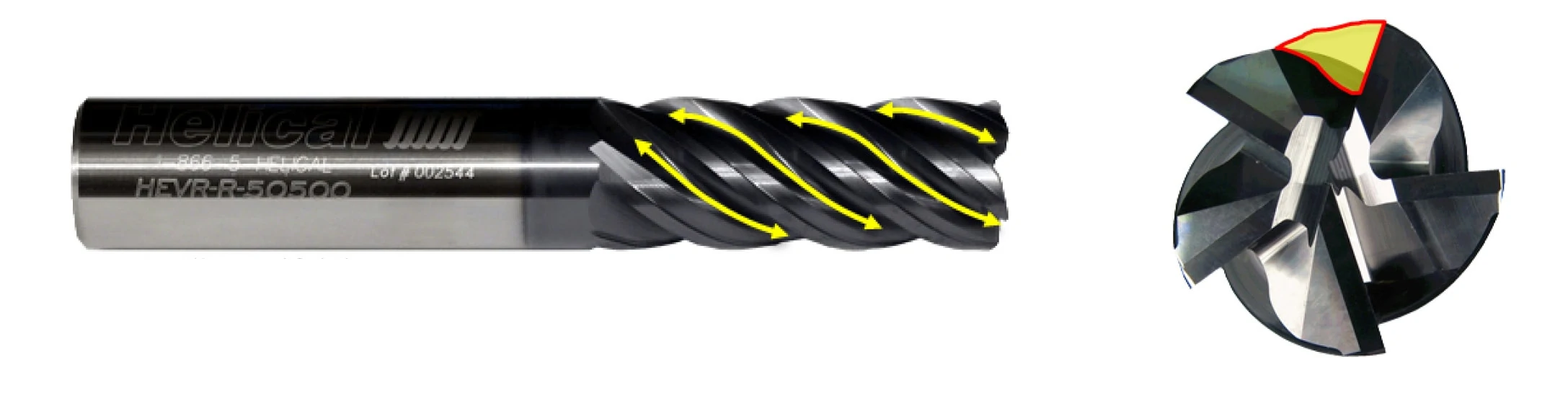
Flutes
Flutes are the easiest part of the end mill to recognize. These are the deep spiraled grooves in the tool that allow for chip formation and evacuation. Simply put, flutes are the part of the anatomy that allows the end mill to cut on its edge.
One consideration that must be made during tool selection is flute count, something we have previously covered in depth. Generally, the lower the flute count, the larger the flute valley – the empty space between cutting edges. This void affects tool strength, but also allows for larger chips with heavier depths of cut, ideal for soft or gummy materials like aluminum. When machining harder materials such as steel, tool strength becomes a larger factor, and higher flute counts are often utilized.
End Mill Profiles
The profile refers to the shape of the cutting end of the tool. It is typically one of three options: square, corner radius, and ball.
Square Profile End Mills
Square profile tooling features flutes with sharp corners that are squared off at a 90° angle.
Corner Radius End Mills
This type of tooling breaks up a sharp corner with a radius form. This rounding helps distribute cutting forces more evenly across the corner, helping to prevent wear or chipping while prolonging functional tool life. A tool with larger radii can also be referred to as “bull nose.”
Ball Profile End Mills
This type of tooling features flutes with no flat bottom, rounded off at the end creating a “ball nose” at the tip of the tool.
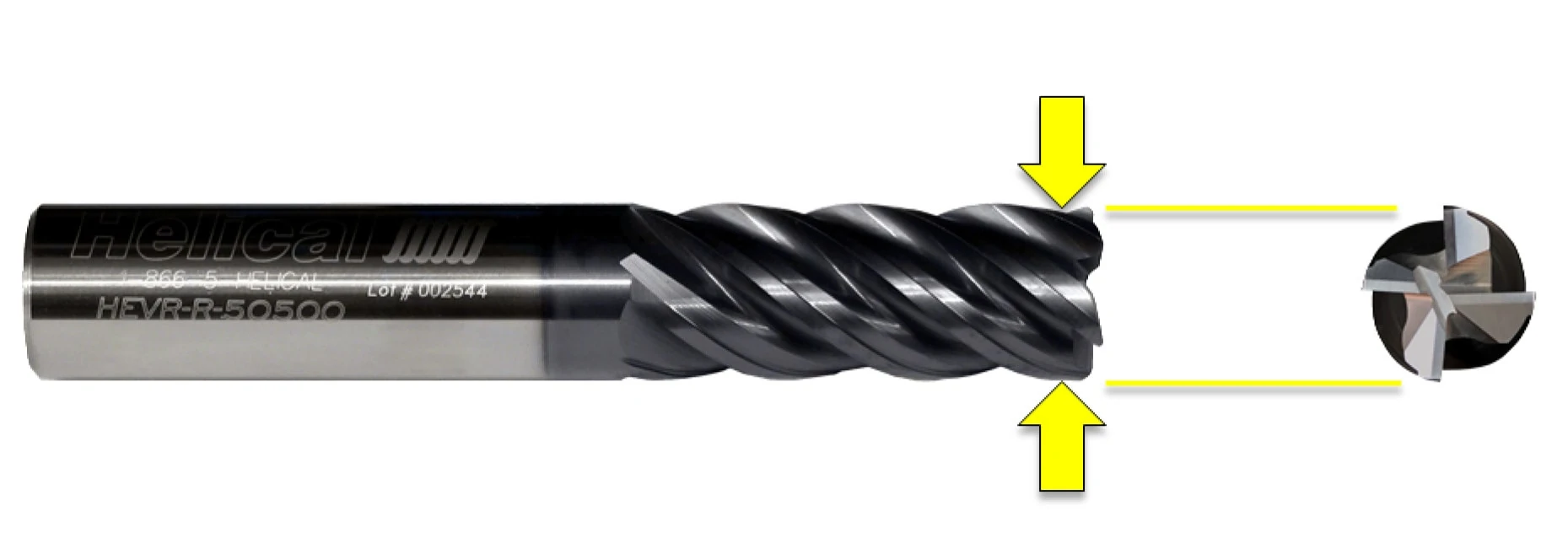
Cutter Diameter
The cutter diameter is often the first thing machinists look for when choosing a tool for their job. This dimension refers to the diameter of the theoretical circle formed by the cutting edges as the tool rotates.
Shank Diameter
The shank diameter is the width of the shank – the non-cutting end of the tool that is held by the tool holder. This measurement is important to note when choosing a tool to ensure that the shank is the correct size for the holder being used. Shank diameters require tight tolerances and concentricity in order to fit properly into any holder.
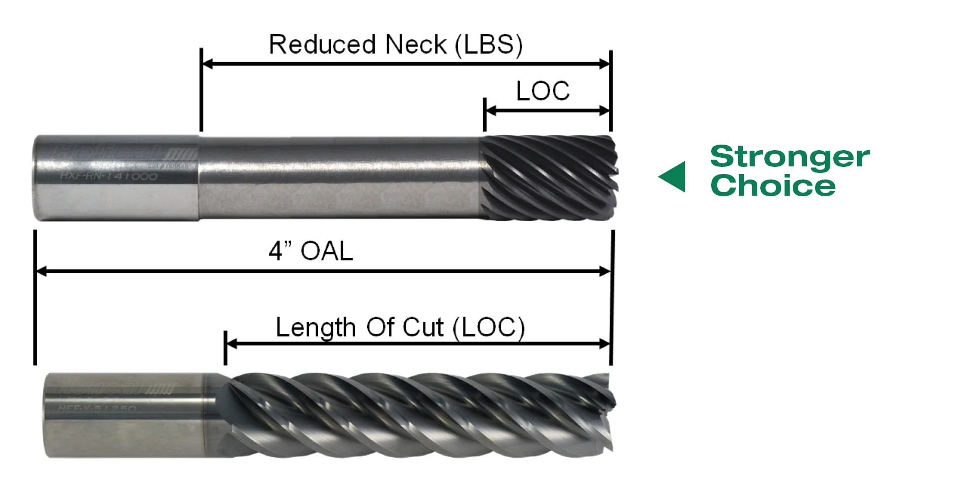
Overall Length (OAL) & Length of Cut (LOC)
Overall length is easy to decipher, as it is simply the measurement between the two axial ends of the tool. This differs from the length of cut (LOC), which is a measurement of the functional cutting depth in the axial direction and does not include other parts of the tool, such as its shank.
The overall reach of an end mill, or length below shank (LBS), is a dimension that describes the necked length of reached tools. It is measured from the start of the necked portion to the bottom of the cutting end of the tool. The neck relief allows space for chip evacuation and prevents the shank from rubbing in deep-pocket milling applications. This is illustrated in the photo below of a tool with a reduced neck.
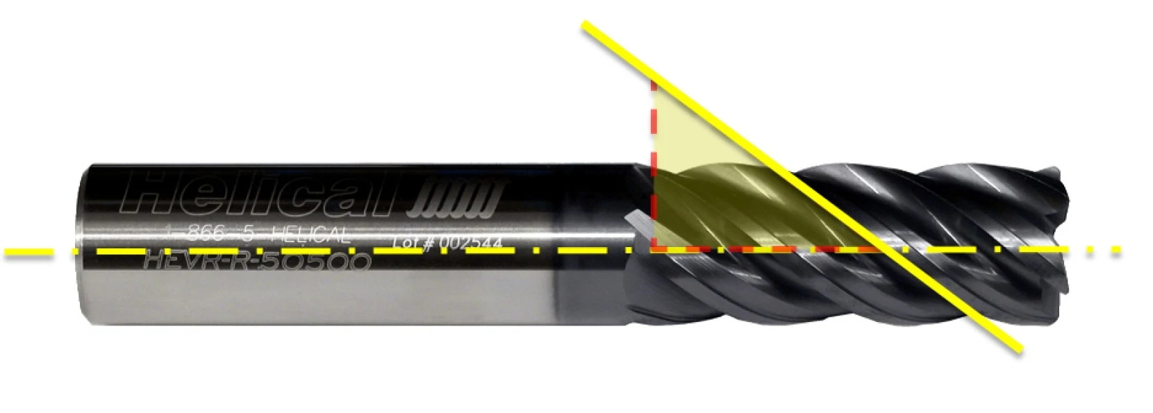
End Mill Helix Angle
The helix angle of a tool is measured by the angle formed between the centerline of the tool and a straight line tangent along the cutting edge. A higher helix angle used for finishing (45°, for example) wraps around the tool faster and makes for a more aggressive cut. A lower helix angle (35°) wraps slower and would have a stronger cutting edge, optimized for the toughest roughing applications.
A moderate helix angle of 40° would result in a tool able to perform basic roughing, slotting, and finishing operations with good results. Implementing a helix angle that varies slightly between flutes is a technique used to combat chatter in some high-performance tooling. A variable helix creates irregular timing between cuts, and can dampen reverberations that could otherwise lead to chatter.
Pitch
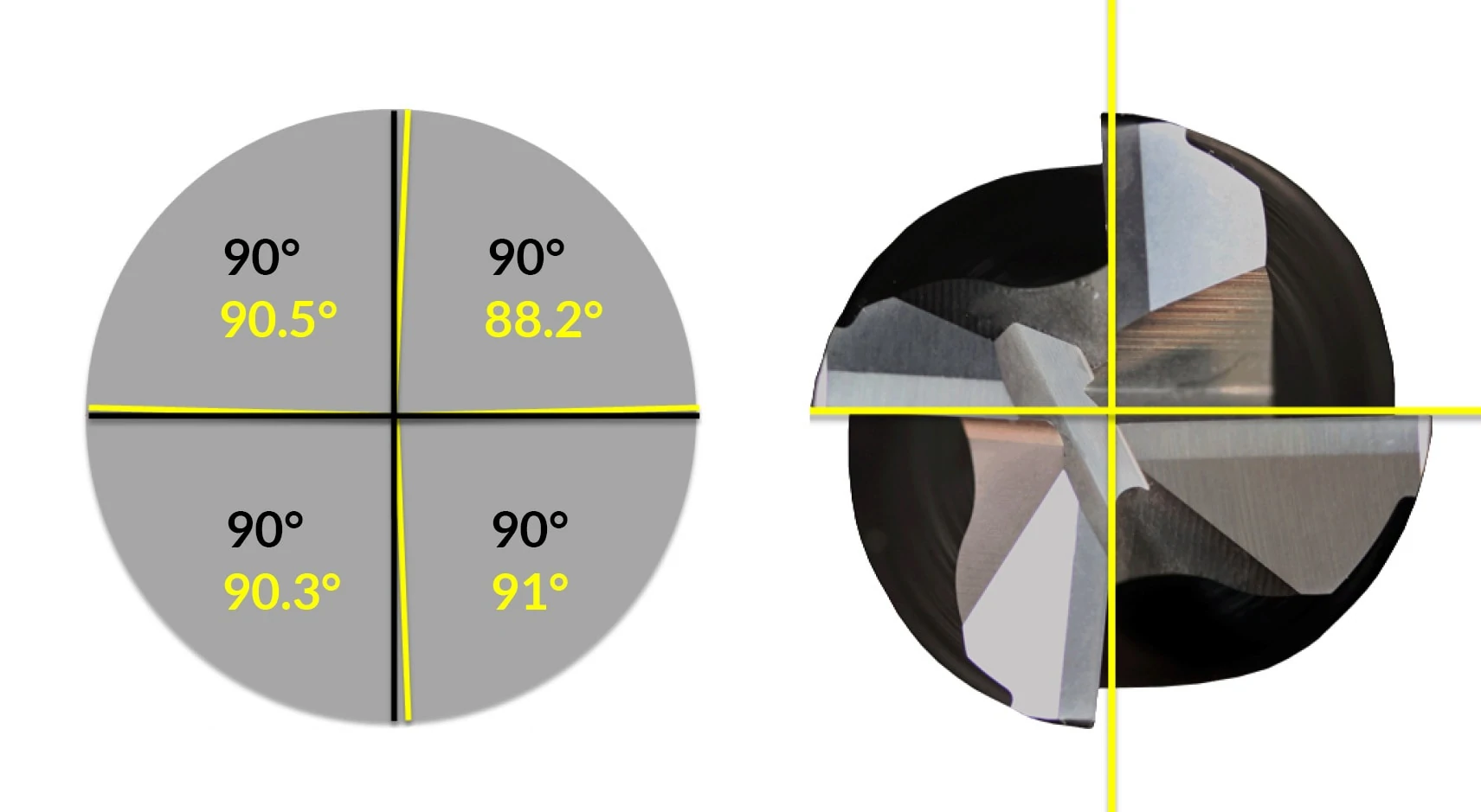
Pitch is the degree of radial separation between the cutting edges at a given point along the length of cut, most visible on the end of the end mill. Using a 4-flute tool with an even pitch as an example, each flute would be separated by 90°. Similar to a variable helix, variable pitch tools have non-constant flute spacing, which helps to break up harmonics and reduce chatter. The spacing can be minor but still able to achieve the desired effect. Using a 4-flute tool with variable pitch as an example, the flutes could be spaced at 90.5 degrees, 88.2 degrees, 90.3 degrees, and 91 degrees (totaling 360°).
https://www.harveyperformance.com/wp-content/uploads/2017/12/Featured-Image-End-Mill-Anatomy-IMG.png4181400Harvey Performance Companyhttp://www.harveyperformance.com/wp-content/uploads/2018/08/Logo_HarveyPerformanceCompany-4.pngHarvey Performance Company2017-12-10 18:00:202023-10-24 09:31:29The Anatomy of an End Mill
Coolant in purpose is widely understood – it’s used to temper high temperatures common during machining, and aid in chip evacuation. However, there are several types and styles, each with its own benefits and drawbacks. Knowing which cnc coolant – or if any – is appropriate for your job can help to boost your shop’s profitability, capability, and overall machining performance.
Coolant or Lubricant Purpose
Coolant and lubricant are terms used interchangeably, though not all coolants are lubricants. Compressed air, for example, has no lubricating purpose but works only as a cooling option. Direct coolants – those which make physical contact with a part – can be compressed air, water, oil, synthetics, or semi-synthetics. When directed to the cutting action of a tool, these can help to fend off high temperatures that could lead to melting, warping, discoloration, or tool failure. Additionally, coolant can help evacuate chips from a part, preventing chip recutting and aiding in part finish.
Coolant can be expensive, however, and wasteful if not necessary. Understanding the amount of coolant needed for your job can help your shop’s efficiency.
CNC coolant is delivered in several different forms – both in properties and pressure. The most common forms include air, mist, flood coolant, high pressure, and Minimum Quantity Lubricant (MQL). Choosing the wrong pressure can lead to part or tool damage, whereas choosing the wrong amount can lead to exhausted shop resources.
Air: Cools and clears chips, but has no lubricity purpose. Air coolant does not cool as efficiently as water or oil-based coolants. For more sensitive materials, air coolant is often preferred over types that come in direct contact with the part. This is true with many plastics, where thermal shock – or rapid expansion and contraction of a part – can occur if direct coolant is applied.
Mist: This type of low pressure coolant is sufficient for instances where chip evacuation and heat are not major concerns. Because the pressure applied is not great in a mist, the part and tool do not undergo additional stresses.
Flood: This low pressure method creates lubricity and flushes chips from a part to avoid chip recutting, a common and tool damaging occurrence.
High Pressure: Similar to flood coolant, but delivered in greater than 1,000 psi. This is a great option for chip removal and evacuation, as it blasts the chips away from the part. While this method will effectively cool a part immediately, the pressure can be high enough to break miniature diameter tooling. This method is used often in deep pocket or drilling operations, and can be delivered via coolant through tooling, or coolant grooves built into the tool itself. Harvey Tool offers Coolant Through Drills, while Titan USA proudly offers Coolant-Fed ThreadMills
Minimum Quantity Lubricant (MQL): Every machine shop focuses on how to gain a competitive advantage – to spend less, make more, and boost shop efficiency. That’s why many shops are opting for MQL, along with its obvious environmental benefits. Using only the necessary amount of coolant will dramatically reduce costs and wasted material. This type of lubricant is applied as an aerosol, or an extremely fine mist, to provide just enough coolant to perform a given operation effectively.
To see all of these coolant styles in action, check out the video below from our partners at CimQuest.
In Conclusion
CNC coolant is all-too-often overlooked as a major component of a machining operation. The type of coolant or lubricant, and the pressure at which it’s applied, is vital to both machining success and optimum shop efficiency. Coolant can be applied as compressed air, mist, in a flooding property, or as high pressure. Certain machines also are MQL able, meaning they can effectively restrict the amount of coolant being applied to the very amount necessary to avoid being wasteful.
https://www.harveyperformance.com/wp-content/uploads/2017/12/Feature-Image-Coolant-for-CNC-Machining-IMG.jpg5251400Harvey Performance Companyhttp://www.harveyperformance.com/wp-content/uploads/2018/08/Logo_HarveyPerformanceCompany-4.pngHarvey Performance Company2017-12-05 15:09:342022-04-20 16:52:22What You Need to Know About Coolant for CNC Machining
We use cookies to ensure that we give you the best experience on our website. If you continue to use this site we will assume that you are happy with it.Ok