Tag Archive for: Helical Interpolation

How to Extend the Life of Your End Mill

Breaking and damaging an end mill is oftentimes an avoidable mistake that can be extremely costly for a machine shop. To save time, money, and your end mill it is important to learn some simple tips and tricks to extend tool life.

Properly Prepare Before the Tool Selection Process

The first step of any machining job is selecting the correct end mill for your material and application. However, this doesn’t mean that there should not be an adequate amount of legwork done beforehand to ensure the right decision on a tool is being made. Harvey Tool, Helical Solutions, Titan USA, and Corehog have thousands of different tools for different operations – a vast selection which, if unprepared – can easily result in selecting a tool that’s not the best for your job. To start your preparation, answer the 5 Questions to Ask Before Selecting an End Mill to help you quickly narrow down your selection and better understand the perfect tool you require.

Understand Your Tooling Requirements

It’s important to understand not only what your tool needs, but also general best practices to avoid common machining mishaps. For instance, it is important to use a tool with a length of cut only as long as needed, as the longer a tools length of cut is, the greater the chance of deflection or tool bending, which can decrease its effective life.

end mill being fed coolant cutting into a workpiece to extend tool life

Another factor to consider is the coating composition on a tool. Harvey Tool and Helical Solutions offer many varieties of tool coatings for different materials. Some coatings increase lubricity, slowing tool wear, while others increase the hardness and abrasion resistance of the tool. Not all coatings increase your tool’s life in every material, however. Be wary of coatings that don’t perform well in your part’s material – such as the use of AlTiN coating in Aluminum (Both coating and material are aluminum-based and have a high affinity for each other, which can cause built-up edge and result in chip evacuation problems).

Consider Variable Helix & Pitch Geometry

A feature on many of our high performance end mills is variable helix or variable pitch geometry, which have differently-spaced flutes. As the tool cuts, there are different time intervals between the cutting edges contacting the workpiece, rather than simultaneously on each rotation. The varying time intervals minimizes chatter by reducing harmonics, increasing tool life and producing better results.

Ensure an Effective Tool Holding Strategy

Another factor in prolonging tool life is proper tool holding. A poor tool holding strategy can cause runout, pullout, and scrapped parts. Generally, the most secure connection has more points of contact between the tool holder and tool shank. Hydraulic and Shrink Fit Tool Holders provide increased performance over other tightening methods.

three different end mills in tool holders

Helical also offers shank modifications to all stocked standards and special quotes, such as the ToughGRIP Shank, which provides added friction between the holder and the shank of the tool for a more secure grip; and the Haimer Safe-Lock™, which has grooves on the shank of the tool to help lock it into place in a tool holder.

massive helical end mill in machinists hand

Trust Your Running Parameters, and their Source

After selecting the correct end mill for your job, the next step is to run the tool at the proper speeds and feeds.

Run at the Correct Speed

Understanding the ideal speed to run your machine is key to prolonging tool life. If you run your tool too fast, it can cause suboptimal chip size, ineffective chip evacuation, or even total tool failure. Adversely, running your tool too slowly can result in deflection, bad finish, or decreased metal removal rates.

Push at the Best Feed Rate

Another critical parameter of speeds and feeds is finding the best possible feed rate for your job, for sake of both tool life and achieving maximum shop efficiency. Pushing your tool too aggressively can result in breakage, but being too conservative can lead to recutting chips and excess heat generation, accelerating tool wear.

Use Parameters from Your Tooling Manufacturer

A manufacturer’s speeds and feeds calculations take into account every tool dimension, even those not called out in a catalog and readily available to machinists. Because of this, it’s best to rely on running parameters from tooling manufacturers. Harvey Tool offers speeds and feeds charts for every one of its more than 21,000 tools featured in its catalog, helping machinists to confidently run their tool the first time.

Harvey Performance Company offers the Machining Advisor Pro application, a free, cutting-edge resource that generates custom running parameters for optimized machining with all of Helical Solutions’ and Harvey Tool’s products.

machining advisor pro graphic for pc, laptops, and other devices

Opt for the Right Milling Strategy: Climb vs Conventional

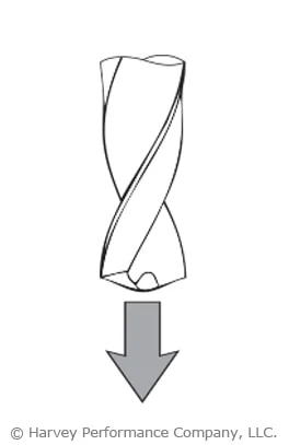
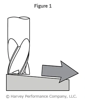
There are two ways to cut material when milling: Climb Milling and Conventional Milling. In conventional milling, the cutter rotates against the feed. In this method, chips will start at theoretical zero and increase in size. Conventional milling is usually recommended for tools with higher toughness, or for breaking through case hardened materials.

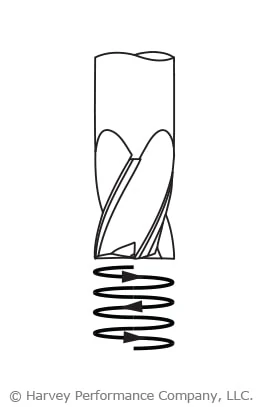
In Climb Milling, the cutter rotates with the feed. Here, the chips start at maximum width and decrease, causing the heat generated to transfer into the chip instead of being left in the tool or work piece. Climb milling also produces a cleaner shear plane, causing less rubbing, decreasing heat, and improving tool life. When climb milling, chips will be removed behind the cutter, reducing your chances of recutting.

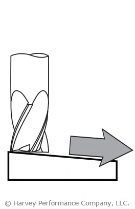
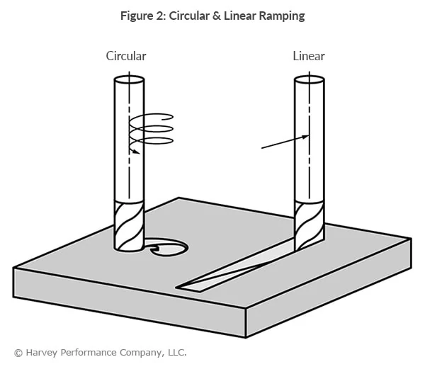
Utilize High Efficiency Milling

High Efficiency Milling (HEM), is a roughing technique that uses the theory of chip thinning by applying a smaller radial depth of cut (RDOC) and a larger axial depth of cut (ADOC). The parameters for HEM are similar to that of finishing, but with increased speeds and feeds, allowing for higher material removal rates (MRR). HEM utilizes the full length of cut instead of just a portion of the cutter, allowing heat to be distributed across the cutting edge, maximizing tool life and productivity. This reduces the possibility of accelerated tool wear and breakage.

Decide On Coolant Usage & Delivery

Coolant can be an extremely effective way to protect your tool from premature wear and possible tool breakage. There are many different types of coolant and methods of delivery to your tool. Coolant can come in the form of compressed air, water-based, straight oil-based, soluble oil-based, synthetic or semi-synthetic. It can be delivered as mist, flood, high pressure or minimum quantity lubricant.

Appropriate coolant type and delivery vary depending on your application and tool. For example, using a high pressure coolant with miniature tooling can lead to tool breakage due to the fragile nature of extremely small tools. In applications of materials that are soft and gummy, flood coolant washes away the long stringy chips to help avoid recutting and built-up edge, preventing extra tool wear.

Extend Your Tool’s Life

The ability to maximize tool life saves you time, money and headaches. To get the best possible outcome from your tool, you first need to be sure you’re using the best tool for your job. Once you find your tool, ensure that your speeds and feeds are accurate and are from your tooling manufacturer. Nobody knows the tools better than they do. Finally, think about how to run your tool: the rotation of your cutter, whether utilizing an HEM approach is best, and how to introduce coolant to your job.

What You Need to Know About Coolant for CNC Machining

Coolant in purpose is widely understood – it’s used to temper high temperatures common during machining, and aid in chip evacuation. However, there are several types and styles, each with its own benefits and drawbacks. Knowing which cnc coolant – or if any – is appropriate for your job can help to boost your shop’s profitability, capability, and overall machining performance.

Coolant or Lubricant Purpose

Coolant and lubricant are terms used interchangeably, though not all coolants are lubricants. Compressed air, for example, has no lubricating purpose but works only as a cooling option. Direct coolants – those which make physical contact with a part – can be compressed air, water, oil, synthetics, or semi-synthetics. When directed to the cutting action of a tool, these can help to fend off high temperatures that could lead to melting, warping, discoloration, or tool failure. Additionally, coolant can help evacuate chips from a part, preventing chip recutting and aiding in part finish.

Coolant can be expensive, however, and wasteful if not necessary. Understanding the amount of coolant needed for your job can help your shop’s efficiency.

Click Here to Shop Harvey Tool’s Fully Stocked Offering of Deep Hole Coolant Through Drills

Types of Coolant Delivery

CNC coolant is delivered in several different forms – both in properties and pressure. The most common forms include air, mist, flood coolant, high pressure, and Minimum Quantity Lubricant (MQL). Choosing the wrong pressure can lead to part or tool damage, whereas choosing the wrong amount can lead to exhausted shop resources.

Air: Cools and clears chips, but has no lubricity purpose. Air coolant does not cool as efficiently as water or oil-based coolants. For more sensitive materials, air coolant is often preferred over types that come in direct contact with the part. This is true with many plastics, where thermal shock – or rapid expansion and contraction of a part – can occur if direct coolant is applied.

Mist: This type of low pressure coolant is sufficient for instances where chip evacuation and heat are not major concerns. Because the pressure applied is not great in a mist, the part and tool do not undergo additional stresses.

Flood: This low pressure method creates lubricity and flushes chips from a part to avoid chip recutting, a common and tool damaging occurrence.

High Pressure: Similar to flood coolant, but delivered in greater than 1,000 psi. This is a great option for chip removal and evacuation, as it blasts the chips away from the part. While this method will effectively cool a part immediately, the pressure can be high enough to break miniature diameter tooling. This method is used often in deep pocket or drilling operations, and can be delivered via coolant through tooling, or coolant grooves built into the tool itself. Harvey Tool offers Coolant Through Drills, while Titan USA proudly offers Coolant-Fed ThreadMills

Minimum Quantity Lubricant (MQL): Every machine shop focuses on how to gain a competitive advantage – to spend less, make more, and boost shop efficiency. That’s why many shops are opting for MQL, along with its obvious environmental benefits. Using only the necessary amount of coolant will dramatically reduce costs and wasted material. This type of lubricant is applied as an aerosol, or an extremely fine mist, to provide just enough coolant to perform a given operation effectively.

To see all of these coolant styles in action, check out the video below from our partners at CimQuest.

In Conclusion

CNC coolant is all-too-often overlooked as a major component of a machining operation. The type of coolant or lubricant, and the pressure at which it’s applied, is vital to both machining success and optimum shop efficiency. Coolant can be applied as compressed air, mist, in a flooding property, or as high pressure. Certain machines also are MQL able, meaning they can effectively restrict the amount of coolant being applied to the very amount necessary to avoid being wasteful.

Most Common Methods of Tool Entry

Tool entry is pivotal to machining success, as it’s one of the most punishing operations for a cutter. Entering a part in a way that’s not ideal for the tool or operation could lead to a damaged part or exhausted shop resources. Below, we’ll explore the most common part entry methods, as well as tips for how to perform them successfully.


Pre-Drilled Hole

Pre-drilling a hole to full pocket depth (and 5-10% larger than the end mill diameter) is the safest practice of dropping your end mill into a pocket. This method ensures the least amount of end work abuse and premature tool wear. It also facilitates smoother chip evacuation, reducing the risk of chip buildup and potential tool breakage. Machinists often use this technique when working with materials prone to chip welding or built-up edge formation, ensuring consistent machining performance.

tool entry predrill


Helical Interpolation

Helical Interpolation is a very common and safe practice of tool entry with ferrous materials. Employing corner radius end mills during this operation will decrease tool wear and lessen corner breakdown. With this method, use a programmed helix diameter of greater than 110-120% of the cutter diameter. Moreover, helical interpolation offers advantages in achieving precise surface finishes, making it a preferred choice for applications requiring high precision and surface quality, such as aerospace and medical device manufacturing.

helical interpolation


Ramping-In

This type of operation can be very successful, but institutes many different torsional forces the cutter must withstand. A strong core is key for this method, as is room for proper chip evacuation. Using tools with a corner radius, which strengthen its cutting portion, will help. Additionally, ramping-in allows for efficient material removal with reduced axial forces, minimizing workpiece distortion and enhancing dimensional accuracy. Machinists often employ this technique in contouring and pocketing operations, where maintaining part integrity is crucial.

ramping

Suggested Starting Ramp Angles:

Hard/Ferrous Materials: 1°-3°

Soft/Non-Ferrous Materials: 3°-10°

For more information on this popular tool entry method, see Ramping to Success.


Arcing

This method of tool entry is similar to ramping in both method and benefit. However, while ramping enters the part from the top, arcing does so from the side. The end mill follows a curved tool path, or arc, when milling, this gradually increasing the load on the tool as it enters the part. Additionally, the load put on the tool decreases as it exits the part, helping to avoid shock loading and tool breakage. Machinists often utilize this technique in mold making, die sinking, and 3D contouring operations, enhancing productivity and surface finish quality.

arching with end mill


Straight Plunge

This is a common, yet often problematic method of entering a part. A straight plunge into a part can easily lead to tool breakage. If opting for this machining method, however, certain criteria must be met for best chances of machining success. The tool must be center cutting, as end milling incorporates a flat entry point making chip evacuation extremely difficult. Drill bits are intended for straight plunging, however, and should be used for this type of operation.

tool entry


Straight Tool Entry

Straight entry into the part takes a toll on the cutter, as does a straight plunge. Until the cutter is fully engaged, the feed rate upon entry is recommended to be reduced by at least 50% during this operation. Machinists often resort to straight tool entry in simple machining operations with limited tool access or where other entry methods are impractical. However, it’s crucial to monitor tool wear and chip evacuation carefully to prevent chip buildup and potential tool breakage. Adjusting cutting parameters based on material properties and part geometry can further enhance machining efficiency and tool life.

tool entry


Roll-In Tool Entry

Rolling into the cut ensures a cutter to work its way to full engagement and naturally acquire proper chip thickness. The feed rate in this scenario should be reduced by 50%. Roll-in tool entry is particularly advantageous in slotting and profiling operations, where maintaining consistent chip thickness is critical for surface finish quality and dimensional accuracy. Machinists often utilize this technique in high-speed machining applications, maximizing material removal rates while minimizing tool wear and heat generation.

tool entry

Mastering various tool entry techniques is essential for machining success. By understanding and implementing these methods effectively, machinists can optimize performance while prolonging the lifespan of their tools. Continual evaluation of cutting conditions and adaptation of entry strategies based on material properties and part geometry are key to achieving superior machining results.

Ramping to Success

Poor tool life and premature tool failure are concerns in every machining application. Something as simple as tool path selection – and how a tool first enters a part – can make all the difference. Tool entry has a great deal of influence on its overall success, as it’s one of the most punishing operations for a cutter. Ramping into a part, via a circular or linear toolpath, is one of the most popular and oftentimes the most successful methods (Figure 1). Below, learn what ramping is, its benefits, and in which situations it can be used.

illustrated end mill ramping into part

Check Out Our Micromachining Webinar to Get More Life Out of Your Miniature Cutting Tools

What is Ramping?

Ramping refers to simultaneous radial and axial motion of a cutting tool, making an angular tool path. Oftentimes, this method is used to approach a part when there is a need to create closed forms such as pockets, cavities, engravings, and holes. In doing so, the need to plunge with an end mill or drill to create a starting point is eliminated. Ramping is particularly important in micromachining where even the slightest imbalance in cutting forces can cause tool failure.

There are two types of ramping toolpaths: Linear and Circular (Figure 2 ).

circular and linear ramping

Linear Ramping involves moving a cutting tool along two axes (the z-axis and one of the x, y axes). This method has significant more radial engagement with complementary increased cutting forces distributed across only two axes.

Circular Ramping (Helical Interpolation) has a spiral motion of the cutting tool that engages all three axes (x, y, and z axes). This method typically has less radial engagement on the cutting tool, with the cutting forces distributed across the three different axes. This is the recommended method, as it ensures the longest tool life.

Suggested Starting Ramp Angles:

Soft/Non-Ferrous Materials: 3° – 10°

Hard/Ferrous Materials 1° – 3°

Benefits of Ramping

When a tool enters the part via a Ramping method, it gradually increases in depth, preventing any shock loading on end mills. This reduces costs resulting from unnecessary tool breakage. Ramping produces smaller chips when compared to plunging, which makes chip evacuation faster and easier. As a result, cycle time can be decreased by running the end mill at faster parameters. Ramping also creates an extra space in the tool changer that would otherwise be occupied by a drill purposed with machining a starter hole.

Arcing

Similar to ramping in both method and benefit, arcing is another technique of approaching a workpiece (See Figure 3).

illustration of end mill arcing tool entry

While ramping enters the part from the top, arcing enters from the side. The end mill follows a curved tool path (or arc) when milling, thus gradually increasing the load on the tool as the tool enters the part, as well as gradually decreasing the load as the tool exits the part. In this way, shock loading and possible tool breakage are avoided.

For more information on ramping, arcing, and other tool entry methods, please see Helical Solutions’ “Types of Tool Entry.”