Tag Archive for: tool breakage

5 Things to Know About Helical’s High Feed End Mills

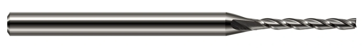
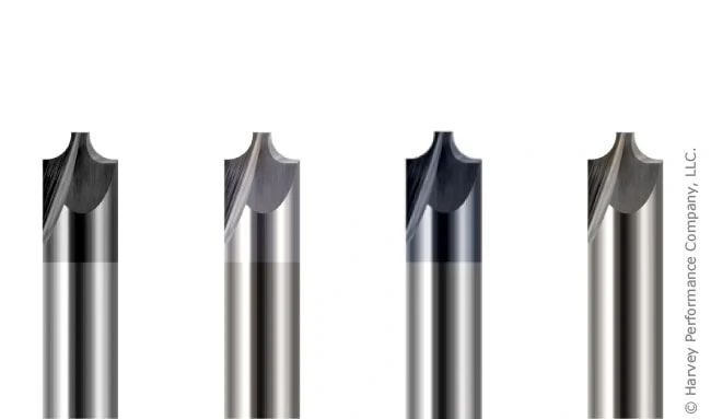
Helical Solutions‘ High Feed End Mills provide many opportunities for machinists, and feature a special end profile to increase machining efficiencies. A High Feed End Mill is a High Efficiency Milling (HEM) style tool with specialized end geometry that utilizes chip thinning, allowing for drastically increased feed rates in certain applications. While standard end mills have square, corner radius, or ball profiles, this Helical tool has a specialized, very specific design that takes advantage of chip thinning, resulting in a tool that can be pushed harder than a traditional end mill.

helical solutions high feed end mills ad with both solid round and coolant through options

Below are 5 things that all machinists should know about this exciting Helical Solutions product offering.

1. They excel in applications with light axial depths of cut

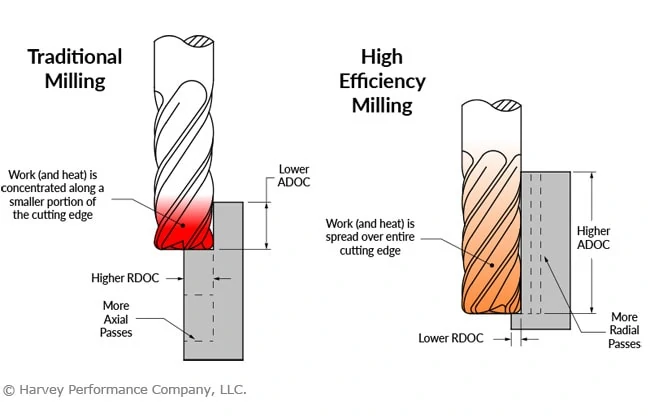
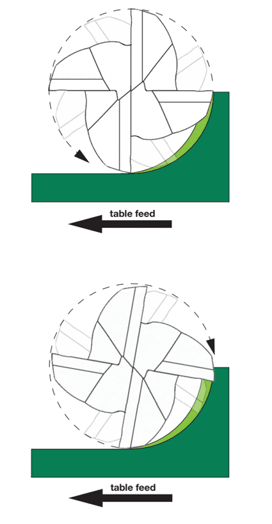
A High Feed End Mill is designed to take a large radial depth of cut (65% to 100% of the cutter diameter) with a small axial depth of cut (2.5% to 5% diameter) depending on the application. This makes them perfect for face milling, roughing, slotting, deep pocketing, and 3D milling. Where HEM toolpaths involve light radial depths of cut and heavy axial depths of cut, these utilize high radial depths of cut and smaller axial depths of cut.

2. This tool reduces radial cutting forces

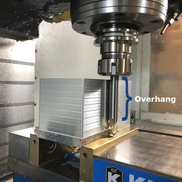
The end profile of this tool is designed to direct cutting forces upward along the axis of the tool and into the spindle. This reduces radial cutting forces which cause deflection, allowing for longer reach tools while reducing chatter and other issues that may otherwise lead to tool failure. The reduction of radial cutting forces makes this tool excellent for use in machines with lower horsepower, and in thin wall machining applications.

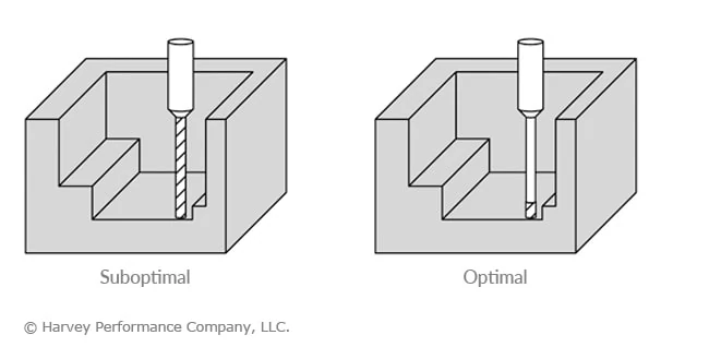
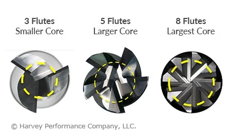
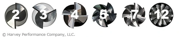
3. High Feed End Mills are rigid tools

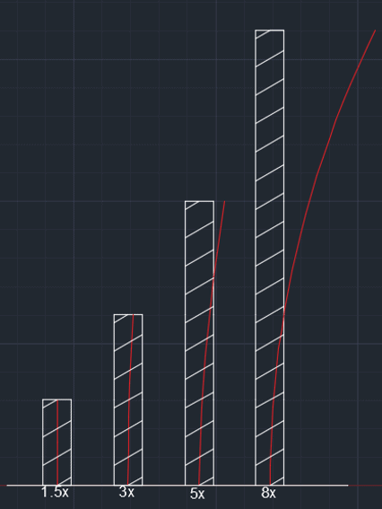
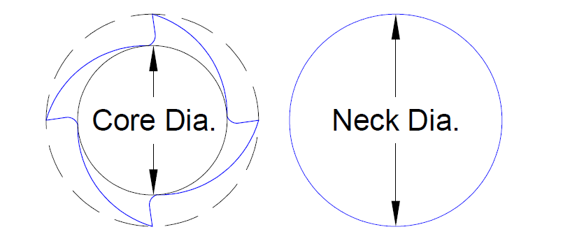
The design and short length of cut of these end mills work in tandem with the end geometry to produce a tool with a strong core, further limiting deflection and allowing for tools with greater reach lengths.

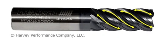
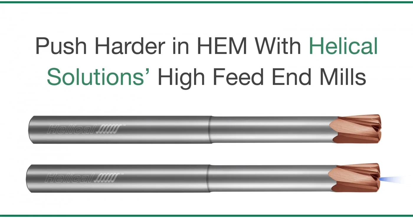
Push Harder in HEM With Helical Solutions’ High Feed End Mills

4. They can reduce cycle times

In high RDOC, low ADOC applications, these tools can be pushed significantly faster than traditional end mills, saving time and money over the life of the tool.

5. High Feed End Mills are well suited for hard materials

The rigidity and strength of High Feed End Mills make them excellent in challenging to machine materials. Helical’s High Feed End Mills come coated with Tplus coating, which offers high hardness and extended tool life in high temp alloys and ferrous materials up to 45Rc.

In summary, these tools with specialized end geometry that utilizes chip thinning and light axial depths of cut to allow for significantly increased feed rates in face milling, slotting, roughing, deep pocket milling, and 3D milling applications. The end profile of a High Feed End Mill applies cutting forces back up into the spindle, reducing radial forces that lead to deflection in long reach applications. Combining this end geometry with a stubby length of cut results in a tool that is incredibly rigid and well suited for harder, difficult to machine materials.

Tool Deflection & Its Remedies

What is Tool Deflection?

Every machinist must be aware of tool deflection, as too much deflection can lead to catastrophic failure in the tool or workpiece. Deflection is the displacement of an object under a load causing curvature and/or fracture.

For Example: When looking at a diving board at rest without the pressure of a person’s weight upon it, the board is straight. But as the diver progresses down further to the end of the board, it bends further. Deflection in tooling can be thought of in a similar way.

Signs of Tool Deflection

Tool Deflection Remedies

Minimize Overhang

Overhang refers to the distance a tool is sticking out of the tool holder. Simply, as overhang increases, the tool’s likelihood of deflection increases. The larger distance a tool hangs out of the holder, the less shank there is to grip, and depending on the shank length, this could lead to harmonics in the tool that can cause fracture. Simply put, For optimal working conditions, minimize overhang by chucking the tool as much as possible.

extended reach tool in tool holder with overhang depth called out
Image Source: @NuevaPrecision

Long Flute vs. Long Reach

Another way to minimize deflection is having a full grasp on the differences between a long flute and a long reach tool. The reason for such a difference in rigidity between the two is the core diameter of the tool. The more material, the more rigid the tool; the shorter the length of flute, the more rigid the tool and the longer the tool life. While each tooling option has its benefits and necessary uses, using the right option for an operation is important.

The below charts illustrate the relationship between force on the tip and length of flute showing how much the tool will deflect if only the tip is engaged while cutting. One of the key ways to get the longest life out of your tool is by increasing rigidity by selecting the smallest reach and length of cut on the largest diameter tool.

tool deflection in relation to length of tool

tool deflection graph

Click Here to Learn More About Proper Tool Holding and Runout

When to Opt for a Long Reach Tool

Reached tools are typically used to remove material where there is a gap that the shank would not fit in, but a noncutting extension of the cutter diameter would. This length of reach behind the cutting edge is also slightly reduced from the cutter diameter to prevent heeling (rubbing of noncutting surface against the part). Reached tools are one of the best tools to add to a tool crib because of their versatility and tool life.

long reach ball end mill
Long Reach Tool: Variable Helix End Mills for Exotic Alloys – Ball – Long Reach, Stub Flute

When to Opt for a Long Flute Tool

Long Flute tools have longer lengths of cut and are typically used for either maintaining a seamless wall on the side of a part, or within a slot for finishing applications. The core diameter is the same size throughout the cutting length, leading to more potential for deflection within a part. This possibly can lead to a tapered edge if too little of the cutting edge is engaged with a high feed rate. When cutting in deep slots, these tools are very effective. When using HEM, they are also very beneficial due to their chip evacuation capabilities that reached tools do not have.

long flute end milling tool
Long Flute Tool: Miniature End Mills – Square Long Flute

Deflection & Tool Core Strength

Diameter is an important factor when calculating deflection. Machinists oftentimes use the cutter diameter in the calculation of long flute tools, when in actuality the core diameter (shown below) is the necessary dimension. This is because the fluted portion of a tool has an absence of material in the flute valleys. For a reached tool, the core diameter would be used in the calculation until its reached portion, at which point it transitions to the neck diameter. When changing these values, it can lower deflection to a point where it is not noticeable for the reached tool but could affect critical dimensions in a long flute tool.

core diameter vs neck diameter infographic

Deflection Summarized

Tool deflection can cause damage to your tool and scrap your part if not properly accounted for prior to beginning a job. Be sure to minimize the distance from the tool holder to the tip of the tool to keep deflection to a minimum. For more information on ways to reduce tool deflection in your machining, view Diving into Depth of Cut.

Selecting the Right Harvey Tool Miniature Drill

Among Harvey Tool’s expansive holemaking solutions product offering are several different types of miniature drill options and their complements. Options range from Miniature Spotting Drills to Miniature High Performance Drills – Deep Hole – Coolant Through. But which tools are appropriate for the hole you aim to leave in your part? Which tool might your current carousel be missing, leaving efficiency and performance behind? Understanding how to properly fill your tool repertoire for your desired holemaking result is the first step toward achieving success.

Pre-Drilling Considerations

Miniature Spotting Drills

Depending on the depth of your desired machined hole and its tolerance mandates, as well as the surface of the machine you will be drilling, opting first for a Miniature Spotting Drill might be beneficial. This tool pinpoints the exact location of a hole to prevent common deep-hole drilling mishaps such as walking, or straying from a desired path. It can also help to promote accuracy in instances where there is an uneven part surface for first contact. Some machinists even use Spotting Drills to leave a chamfer on the top of a pre-drilled hole. For extremely irregular surfaces, however, such as the side of a cylinder or an inclined plane, a Flat Bottom Drill or Flat Bottom Counterbore may be needed to lessen these irregularities prior to the drilling process.

harvey tool miniature spotting drill with dimension callout marks

Tech Tip: When spotting a hole, the spot angle should be equal to or wider than the angle of your chosen miniature drill. Simply, the miniature drill tip should contact the part before its flute face does.

infographic showcasing proper spot angle for spot drilling in relation to drills included angle

Selecting the Right Miniature Drill

Harvey Tool stocks several different types of miniature drills, but which option is right for you, and how does each drill differ in geometry?

Miniature Drills

Harvey Tool Miniature Drills are popular for machinists seeking flexibility and versatility with their holemaking operation. Because this line of tooling is offered uncoated in sizes as small as .002” in diameter, machinists no longer need to compromise on precision to reach very micro sizes. Also, this line of tooling is designed for use in several different materials where specificity is not required.

harvey tool extended depth miniature drill

Miniature High Performance Drills – Deep Hole – Coolant Through

For situations in which chip evacuation may be difficult due to the drill depth, Harvey Tool’s Deep Hole – Coolant Through Miniature Drills might be your best option. The coolant delivery from the drill tip will help to flush chips from within a hole, and prevent heeling on the hole’s sides, even at depths up to 20 multiples of the drill diameter.

harvey tool miniature deep hole coolant through gun drill

Miniature High Performance Drills – Flat Bottom

Choose Miniature High Performance Flat Bottom Drills when drilling on inclined and rounded surfaces, or when aiming to leave a flat bottom on your hole. Also, when drilling intersecting holes, half holes, shoulders, or thin plates, its flat bottom tool geometry helps to promote accuracy and a clean finish.

harvey tool miniature flat bottom drill with dimension callouts

Miniature High Performance Drills – Aluminum Alloys

The line of High Performance Drills for Aluminum Alloys feature TiB2 coating, which has an extremely low affinity to Aluminum and thus will fend off built-up edge. Its special 3 flute design allows for maximum chip flow, hole accuracy, finish, and elevated speeds and feeds parameters in this easy-to-machine material.

miniature drill for aluminum from harvey tool with dimension callouts

Miniature High Performance Drills – Hardened Steels

Miniature High Performance Drills – Hardened Steels features a specialized flute shape for improved chip evacuation and maximum rigidity. Additionally, each drill is coated in AlTiN Nano coating for hardness, and heat resistance in materials 48 Rc to 68 Rc.

miniature drill for hardened steel with dimension callouts

Miniature High Performance Drills – Prehardened Steels

As temperatures rise during machining, the AlTiN coating featured on Harvey Tool’s Miniature High Performance Drills – Prehardened Steels creates an aluminum oxide layer which helps to reduce thermal conductivity of the tool and helps to promote heat transfer to the chip, as well as improve lubricity and heat resistance in ferrous materials.

miniature drill for prehardened steel with dimension callouts

Post-Drilling Considerations

Miniature Reamers

For many operations, drilling the actual hole is only the beginning of the job. Some parts may require an ultra-tight tolerance, for which a Miniature Reamer (tolerances of +.0000″/-.0002″ for uncoated and +.0002″/-.0000″ for AlTiN Coated) can be used to bring a hole to size. harvey tool straight flute miniature reamer with dimension callouts

Tech Tip: In order to maintain appropriate stock removal amounts based on the reamer size, a hole should be pre-drilled at a diameter that is 90-94 percent of the finished reamed hole diameter.

Flat Bottom Counterbores

Other operations may require a hole with a flat bottom to allow for a superior connection with another part. Flat Bottom Counterbores leave a flat profile and straighten misaligned holes. For more information on why to use a Flat Bottom Counterbore, read 10 Reasons to Use Flat Bottom Tools.

harvey tool flat bottom counterbores with dimension callouts

Key Next Steps

Now that you’re familiar with miniature drills and complementary holemaking tooling, you must now learn key ways to go about the job. Understanding the importance of pecking cycles, and using the correct approach, is vital for both the life of your tool and the end result on your part. Read this post’s complement “Choosing the Right Pecking Cycle Approach,” for more information on the approach that’s best for your application.

Choosing the Right Pecking Cycle Approach

Utilizing a proper pecking cycle strategy when drilling is important to both the life of your tool and its performance in your part. Recommended cycles vary depending on the drill being used, the material you’re machining, and your desired final product.

Start to Boost Your Accuracy with Harvey Tool’s Drilling Guidebook.

What are Pecking Cycles?

Rather than drill to full drill depth in one single plunge, pecking cycles involve several passes – a little at a time. Peck drilling aids the chip evacuation process, helps support tool accuracy while minimizing walking, prevents chip packing and breakage, and results in a better all around final part.

Miniature Drills

miniature drill pecking cycles

High Performance Drills – Flat Bottom

high performance drill pecking cycles

High Performance Drills – Aluminum & Aluminum Alloys

aluminum pecking cycles

Note: For hole depths 12x or greater, a pilot hole of up to 1.5X Diameter is recommended.

High Performance Drills – Hardened Steels

hardened steels chart
High Performance Drills – Prehardened Steels

prehardened steels chart

Key Pecking Cycle Takeaways

From the above tables, it’s easy to identify how recommended peck drilling cycles change based on the properties of the material being machined. Unsurprisingly, the harder the material is, the shorter the recommended pecking depths are. As always, miniature drills with a diameter of less than .010″ are extremely fragile and require special precautions to avoid immediate failure. For help with your specific job, contact the Harvey Tool Technical Team at 800-645-5609 or [email protected]

8 Ways You’re Killing Your End Mill


Running It Too Fast or Too Slow Can Impact Tool Life

Determining the right speeds and feeds for your tool and operation can be a complicated process, but understanding the ideal speed (RPM) is necessary before you start running your machine to ensure proper tool life. Running a tool too fast can cause suboptimal chip size or even catastrophic tool failure. Conversely, a low RPM can result in deflection, bad finish, or simply decreased metal removal rates. If you are unsure what the ideal RPM for your job is, contact the tool manufacturer.

Feeding It Too Little or Too Much

Another critical aspect of speeds and feeds, the best feed rate for a job varies considerably by tool type and workpiece material. If you run your tool with too slow of a feed rate, you run the risk of recutting chips and accelerating tool wear. If you run your tool with too fast of a feed rate, you can cause tool fracture. This is especially true with miniature tooling.

Using Traditional Roughing

infographic of traditional versus high efficiency milling depths of cut and heat generation

While traditional roughing is occasionally necessary or optimal, it is generally inferior to High Efficiency Milling (HEM). HEM is a roughing technique that uses a lower Radial Depth of Cut (RDOC) and a higher Axial Depth of Cut (ADOC). This spreads wear evenly across the cutting edge, dissipates heat, and reduces the chance of tool failure. Besides dramatically increasing tool life, HEM can also produce a better finish and higher metal removal rate, making it an all-around efficiency boost for your shop.

Using Improper Tool Holding and its Effect on Tool Life

end mill held in haimer safe-lock tool holder

Proper running parameters have less of an impact in suboptimal tool holding situations. A poor machine-to-tool connection can cause tool runout, pullout, and scrapped parts. Generally speaking, the more points of contact a tool holder has with the tool’s shank, the more secure the connection. Hydraulic and shrink fit tool holders offer increased performance over mechanical tightening methods, as do certain shank modifications, like Helical’s ToughGRIP shanks and the Haimer Safe-Lock™.

Not Using Variable Helix/Pitch Geometry

infographic showcasing intricacies variable helix end mill

A feature on a variety of high performance end mills, variable helix, or variable pitch, geometry is a subtle alteration to standard end mill geometry. This geometrical feature ensures that the time intervals between cutting edge contact with the workpiece are varied, rather than simultaneous with each tool rotation. This variation minimizes chatter by reducing harmonics, which increases tool life and produces superior results.

Choosing the Wrong Coating Can Wear on Tool Life

four different corner rounding end mills with different tool coatings

Despite being marginally more expensive, a tool with a coating optimized for your workpiece material can make all the difference. Many coatings increase lubricity, slowing natural tool wear, while others increase hardness and abrasion resistance. However, not all coatings are suitable to all materials, and the difference is most apparent in ferrous and non-ferrous materials. For example, an Aluminum Titanium Nitride (AlTiN) coating increases hardness and temperature resistance in ferrous materials, but has a high affinity to aluminum, causing workpiece adhesion to the cutting tool. A Titanium Diboride (TiB2) coating, on the other hand, has an extremely low affinity to aluminum, and prevents cutting edge build-up and chip packing, and extends tool life.

Using a Long Length of Cut

optimal length of cut for proper tool life

While a long length of cut (LOC) is absolutely necessary for some jobs, especially in finishing operations, it reduces the rigidity and strength of the cutting tool. As a general rule, a tool’s LOC should be only as long as needed to ensure that the tool retains as much of its original substrate as possible. The longer a tool’s LOC the more susceptible to deflection it becomes, in turn decreasing its effective tool life and increasing the chance of fracture.

Free Resource: Download the 50+ Page High Efficiency Milling (HEM) Guidebook Today

Choosing the Wrong Flute Count

infographic of face of end mills with varying flute counts

As simple as it seems, a tool’s flute count has a direct and notable impact on its performance and running parameters. A tool with a low flute count (2 to 3) has larger flute valleys and a smaller core. As with LOC, the less substrate remaining on a cutting tool, the weaker and less rigid it is. A tool with a high flute count (5 or higher) naturally has a larger core. However, high flute counts are not always better. Lower flute counts are typically used in aluminum and non-ferrous materials, partly because the softness of these materials allows more flexibility for increased metal removal rates, but also because of the properties of their chips. Non-ferrous materials usually produce longer, stringier chips and a lower flute count helps reduce chip recutting. Higher flute count tools are usually necessary for harder ferrous materials, both for their increased strength and because chip recutting is less of a concern since these materials often produce much smaller chips.

What You Need to Know About Coolant for CNC Machining

Coolant in purpose is widely understood – it’s used to temper high temperatures common during machining, and aid in chip evacuation. However, there are several types and styles, each with its own benefits and drawbacks. Knowing which cnc coolant – or if any – is appropriate for your job can help to boost your shop’s profitability, capability, and overall machining performance.

Coolant or Lubricant Purpose

Coolant and lubricant are terms used interchangeably, though not all coolants are lubricants. Compressed air, for example, has no lubricating purpose but works only as a cooling option. Direct coolants – those which make physical contact with a part – can be compressed air, water, oil, synthetics, or semi-synthetics. When directed to the cutting action of a tool, these can help to fend off high temperatures that could lead to melting, warping, discoloration, or tool failure. Additionally, coolant can help evacuate chips from a part, preventing chip recutting and aiding in part finish.

Coolant can be expensive, however, and wasteful if not necessary. Understanding the amount of coolant needed for your job can help your shop’s efficiency.

Click Here to Shop Harvey Tool’s Fully Stocked Offering of Deep Hole Coolant Through Drills

Types of Coolant Delivery

CNC coolant is delivered in several different forms – both in properties and pressure. The most common forms include air, mist, flood coolant, high pressure, and Minimum Quantity Lubricant (MQL). Choosing the wrong pressure can lead to part or tool damage, whereas choosing the wrong amount can lead to exhausted shop resources.

Air: Cools and clears chips, but has no lubricity purpose. Air coolant does not cool as efficiently as water or oil-based coolants. For more sensitive materials, air coolant is often preferred over types that come in direct contact with the part. This is true with many plastics, where thermal shock – or rapid expansion and contraction of a part – can occur if direct coolant is applied.

Mist: This type of low pressure coolant is sufficient for instances where chip evacuation and heat are not major concerns. Because the pressure applied is not great in a mist, the part and tool do not undergo additional stresses.

Flood: This low pressure method creates lubricity and flushes chips from a part to avoid chip recutting, a common and tool damaging occurrence.

High Pressure: Similar to flood coolant, but delivered in greater than 1,000 psi. This is a great option for chip removal and evacuation, as it blasts the chips away from the part. While this method will effectively cool a part immediately, the pressure can be high enough to break miniature diameter tooling. This method is used often in deep pocket or drilling operations, and can be delivered via coolant through tooling, or coolant grooves built into the tool itself. Harvey Tool offers Coolant Through Drills, while Titan USA proudly offers Coolant-Fed ThreadMills

Minimum Quantity Lubricant (MQL): Every machine shop focuses on how to gain a competitive advantage – to spend less, make more, and boost shop efficiency. That’s why many shops are opting for MQL, along with its obvious environmental benefits. Using only the necessary amount of coolant will dramatically reduce costs and wasted material. This type of lubricant is applied as an aerosol, or an extremely fine mist, to provide just enough coolant to perform a given operation effectively.

To see all of these coolant styles in action, check out the video below from our partners at CimQuest.

In Conclusion

CNC coolant is all-too-often overlooked as a major component of a machining operation. The type of coolant or lubricant, and the pressure at which it’s applied, is vital to both machining success and optimum shop efficiency. Coolant can be applied as compressed air, mist, in a flooding property, or as high pressure. Certain machines also are MQL able, meaning they can effectively restrict the amount of coolant being applied to the very amount necessary to avoid being wasteful.

Work Hardening and When it Should Scare You

What Is Work Hardening

Work hardening is often an unintentional part of the machining process, where the cutting tool generates enough heat in one area to harden the workpiece. It results in plastic deformation which alters the physical structure of the metal being machined. This altered structure affects the machinability of the chosen metal and acts similarly to heat treating. When this occurs the generated speeds and feed requirements will be changed, creating a potential for inefficiency. This makes for a much more difficult machining process and can lead to scrapped parts, broken tools, and serious headaches.

Soften Up Work Hardening With Machining Advisor Pro’s Customizable Speeds and Feeds

What Causes Work Hardening

During machining, the friction between the tool and the workplace generates heat. The heat that is transferred to the workpiece causes the structure of the material to change and in turn harden the material. The degree to which it is hardened depends on the amount of heat being generated in the cutting action and the properties of the material, such as carbon content and other alloying elements. The most influential of these alloying elements include Manganese, Silicon, Nickel, Chromium, and Molybdenum.

While the hardness change will be the highest at the surface of the material, the thermal conductivity of the material will affect how far the hardness changes from the surface of the material.

titanium packed ball bearing

Often times, the thermal properties of a material that makes it appealing for an application are also the main cause of its difficulty to machine. For example, the favorable thermal properties of titanium that allow it to function as a jet turbine are the same properties that cause difficulty in machining it.

Major Problems

Heat Generation

As previously stated, metal work hardening can create some serious problems when machining. The biggest issue is heat generated by the cutting tool and transferring to the workpiece, rather than to the chips. When the heat is transferred to the workpiece, it can cause deformation which will lead to scrapped parts. Stainless Steels and High-Temp Alloys are most prone to work hardening, so extra precaution is needed when machining in these materials.

stringy chips in front of an end mill in the cut

Improper Speeds and Feeds

One other issue that scares a lot of machinists is the chance that a workpiece can harden to the point that it becomes equally as hard as the cutting tool. This is often the case when improper speeds and feeds are used. Incorrect speeds and feeds will cause more rubbing and less cutting, resulting in more heat generation passed to the workpiece. In these situations, machining can become next to impossible, and serious tool wear and eventual tool breakage are inevitable if the tool continues to be fed the same way.

Harvey tool ad for work hardening and speeds and feeds

How To Avoid Work Hardening

There are a few main keys to avoid work hardening: correct speeds and feeds, performing climb milling, selecting appropriate tool coatings, and proper coolant usage. As a general rule of thumb, talking to your tooling manufacturer and using their recommended speeds and feeds is essential for machining success.

Speeds and Feeds

Speeds and feeds become an even bigger priority when you want to avoid heat and tool rubbing, which can both cause serious work hardening. More cutting power and a constant feed rate keeps the tool moving and prevents heat from building up and transferring to the workpiece. The ultimate goal is to get the heat to transfer to the chips, and minimize the heat that is transferred into workpiece and avoiding any deformation of parts. Prior to machining, you should be setting guidelines for each cutting tool to ensure you receive the highest output without compromising on part finish or tool life.

Climb Milling

Conventional milling and climb milling are the two ways to perform CNC cutting operations. In climb milling, the cutter rotates with the feed, while in conventional milling the cutter rotates against the feed. However during conventional milling, the chip width starts at zero then increases thus generating heat at the workpiece. This results in work hardening and faster tool wear over time. On the other hand, climb milling begins at maximum chip width and decreases which transfers heat to the chip rather than the tool or workpiece. Climb milling is advantageous because there is less tool rubbing, minimized chance of chip recutting, and enhanced tool life.

drawing that displays conventional milling vs climb milling in cnc cutting operations

Tool Coating

While friction is often the main culprit of heat generation, the appropriate coating for the material may help combat the severity. Many coatings for ferrous materials reduce the amount of friction generated during cutting action. This added lubricity will reduce the friction on the cutting tool and workpiece, therefore transferring the heat generated to the chip, rather than to the workpiece. Tool coatings also create a natural separation between carbide and the workpiece. This minimizes the internal temperature of the carbide as heat is transferred into the chips and workpiece.

Coolant

Proper coolant usage helps to control the temperature in a cutting operation. Machinists generally choose between using Flooding or High Pressure Coolant options. Flooding the workpiece with coolant may be necessary to maintain the proper temperature, especially when machining in stainless steels and high-temp alloys. This low pressure method creates lubricity to flush chips and avoid chip recutting which commonly damages cutting tools.

high pressure coolant spraying on a part and workpiece during a cnc cutting operation

On the other hand, high pressure coolant delivers enhanced levels of chip evacuation and instant cooling of a part. However, one must be cautious of potentially breaking miniature diameter tooling when using this method due to the higher pressures. Coolant-fed tools can also help to reduce the heat at the contact point, lessening work hardening. While coolant-fed tools are typically a custom modification, saving parts from the scrap heap and using more machine time for the placement part will see the tool pay for itself over time.

Why Flute Count Matters

One of the most important considerations when choosing an end mill is determining which flute count is best for the job at hand. Both material and application play an important role in this critical part of the tool selection process. Understanding the effects of flute count on other tool properties, and how a tool will behave in different situations is an essential consideration in the tool selection process. As end mills have become more and more advanced, certain standards have been created for flute counts in certain materials. While there is obvious overlap due to a myriad of factors, proper flute count is critical for machining success and ensuring you are making the most of your end mill and it’s associated MRR.

Machining Advisor Pro (MAP) Takes Flute Count Into Consideration When Helping You Dial In Running Parameters.

Click Here to Get Started.

Tool Geometry Basics

Generally, tools with more flutes have a larger core and smaller flute valleys than tools with fewer flutes.  More flutes with a larger core can provide both benefits and restrictions depending on the application.  Simply put, a larger core is directly proportional to tool strength; the larger the core, the stronger a tool will be.  In turn, a larger core also reduces the flute depth of a tool, restricting the amount of space for chips to exist.  This can cause issues with chip packing in applications requiring heavy material removal.  However, these considerations only lead us part way when making a decision on which tool to use, and when.

3, 5, and 8 flute end mills and their core sizes in relation to flute valleys

Material Considerations

Traditionally, end mills came in either a 2 flute or 4 flute option.  The widely accepted rule of thumb was to use 2 flutes for machining aluminum and non-ferrous materials, and 4 flutes for machining steel and harder alloys.  As aluminum and non-ferrous alloys are typically much softer than steels, a tool’s strength is less of a concern, a tool can be fed faster, and larger material removal rates (MRR) is facilitated by the large flute valleys of 2 flute tools.

Consequently, ferrous materials are typically much harder, and require the strength of a larger core.  Feed rates are slower, resulting in smaller chips, and allowing for the smaller flute valleys of a larger core tool.  This also allows for more flutes to fit on the tool, which in turn increases productivity.

end mill flute count comparisons

Recently, with more advanced machines and toolpaths, higher flute count tools have become the norm in manufacturing.  Non-ferrous tooling has become largely centered on 3 flute tools. This has created a slight advantage over 2 flute tools by increasing productivity while still affording proper chip evacuation. The softness of non-ferrous materials affords a much deeper flute valley. As previously discussed, this allows the tool to be fed much faster than in ferrous materials. Adding an additional flute increases the productivity of the tool, while still affording machinists faster feed rates.

Ferrous tooling has taken a step further and progressed not only to 5 and 6 flutes, but up to 7 flutes and more in some cases.  With a wider range of hardness, sometimes at the very top of the Rockwell hardness scale, many more flutes have allowed longer tool life, less tool wear, stronger tools, and less deflection.  All of this results in more specialized tools for more specific materials. Material specific tooling combines proper flute counts with coatings that aid in lubricity and heat generation to ensure the most effective end mill possible in the material being machined. The end result is higher MRR and increased productivity across the entire range of ferrous materials that machinists will work with in their shops.

Running Parameters

Just as material considerations will have an impact on the tool you choose, operation type and depth of cut requirements may also have a big impact on the ideal number of flutes for your application.  In roughing applications, lower flute counts may be desirable to evacuate large amounts of chips faster with larger flute valleys.  That said, there is a balance to find, as modern toolpaths such as High Efficiency Milling (HEM) can achieve extreme MRR with a very small step over, and a higher number of flutes.  In a more traditional sense, higher flute counts are great for finishing operations where very small amounts of material are being removed, and greater finish can be achieved with more flutes, not worrying as much about chip evacuation as that phase has already been accomplished during roughing.

helical end mill with lines showcasing the flute valleys

Flute count plays a big role in speeds and feeds calculation as well.  One common rule of thumb is “more flutes, more feed,” but this can be a very detrimental misconception.  Although true in some cases, this is not an infinitely scalable principle.  As stated previously, increasing the number of flutes on a tool limits the size that the flute valleys can be.  While adding a 5th flute to a 4 flute tool theoretically gives you 25% more material removal per revolution with an appropriately increased feed rate, feeding the tool that much faster may overload the tool.  The 25% increase in material removal is more likely closer to 10-15%, given the tool is exactly the same in all other specifications.  Higher flute count tools may require speeds and feeds to be backed off so much in some cases, that a lower flute count may be even more efficient.  Finding the right balance is key in modern milling practices. Consulting a tooling manufacturer’s speeds and feeds will be the perfect starting point, and then machinists can make changes as they see fit to properly accomplish the job at hand.

In all, the importance of flute count identification is critical to continued success at the spindle. Different materials have different strength requirements as well as variability in how much material can be appropriately removed per tooth.

Key Tool Holding Considerations

Each tool holder style has its own unique properties that must be considered prior to beginning a machining operation. A secure machine-to-tool connection will result in a more profitable shop, as a poor connection can cause tool runout, pull-out, scrapped parts, damaged tools, and exhausted shop resources. An understanding of tool holders, shank features, and best practices is therefore pivotal for every machinist to know to ensure reliable tool holding.

Types of Tool Holding

The basic concept of any tool holder is to create a compression force around the cutting tool’s shank that is strong, secure, and rigid. These come in a variety of styles, each with its own spindle interface, taper for clearance, and compression force methods.

Mechanical Spindle Tightening

The most basic way in which spindle compression is generated is by simple mechanical tightening of the holder itself, or a collet within the holder. The downside of this mechanical tightening method of the spindle is its limited number of pressure points. With this style, segments of a collet collapse around the shank, and there is no uniform, concentric force holding the tool around its full circumference.

end mill in tool holder within a cnc machine

Hydraulic Tool Holders

Other methods create a more concentric pressure, gripping the tool’s shank over a larger surface area. Hydraulic tool holders create this scenario. They are tightened via a pressurized fluid inside the bore of the holder, creating a more powerful clamping force on the shank.

Shrink Fit Tool Holders

Shrink fit tool holders are another high quality tool holding mechanism. This method works by using the thermal properties of the device to expand its opening slightly larger than the shank of the tool. The tool is placed inside the holder, after which the holder is allowed to cool, contracting down close to its original size and creating a tremendous compressive force around the shank. Since the expansion of the bore in the tool holder is minuscule, a tight tolerance is needed on the shank to ensure it can fit every time. Shank diameters with h6 tolerances ensure the tool will always work properly and reliably with a shrink fit holder.

Types of Shank Modifications

Along with choosing correctly when it comes to tool holding options, tool shanks can be modified to promote a more secure machine-to-tool connection. These modifications can include added grooves on the shank, flats, or even an altered shank surface to aid in gripping strength.

Weldon Flats

A Weldon flat can be used to create additional strength within the tool holder. The tool holder locks a tool in place with a set screw pushing on a flat area on the tool shank. Weldon flats offer a good amount of pull-out prevention due to the set screw sitting in the recessed shank flat. Often seen as an outdated method of tool holding, this method is most effective for larger, stronger tools where runout is less of a concern.

ToughGRIP Shanks

Helical Solutions offers a ToughGRIP shank modification to its customers, which works by increasing the friction of the shank – making it easier to grip for the tool holder. This modification roughs the shank’s surface while maintaining h6 shrink fit tolerance.

Haimer Safe-Lock™

In the Haimer Safe-Lock system, special drive keys in the chuck interface with grooves in the shank of the tool to prevent pull-out. The end mill effectively screws into the tool holder, which causes a connection that only becomes more secure as the tool is running. Haimer Safe-Lock™ maintains h6 shank tolerances, ensuring an even tighter connection with shrink fit holders.

haimer safe-lock tool holder up close

Key Takeaways

While choosing a proper cutter and running it at appropriate running parameters are key factors to a machining operation, so too is the method used. If opting for an improper tool holding method, one can experience tool pull-out, tool runout, and scrapped jobs. Effective tool holding will prevent premature tool failure and allow machinists to feel confident while pushing the tool to its full potential.

Reducing Tool Runout

Tool runout is a given in any machine shop, and can never be 100% avoided. Thus, it is important to establish an acceptable level of runout for any project, and stay within that range to optimize productivity and prolong tool life. Smaller runout levels are always better, but choice of machine and tool holder, stick-out, tool reach, and many other factors all have an influence on the amount of runout in every setup.

Defining Tool Runout

Tool runout is the measurement of how far a cutting tool, holder, or spindle rotates off of its true axis. This can be seen in low quality end mills where the cutting diameter is true to size when measured while stationary, but measures above tolerance while rotating.

The first step to minimizing runout is understanding what individual factors cause runout in every machine setup. Runout is seen in the accuracy of every cutting tool, collet, tool holder, and spindle. Every added connection between a machine and the workpiece it is cutting will introduce a higher level of runout. Each increase can add to the total runout further and further. Steps should be taken with every piece of tooling and equipment to minimize runout for best performance, increased tool life, and quality finished products.

Measuring Runout

Determining the runout of your system is the first step towards finding how to combat it. Runout is measured using an indicator that measures the variation of a tool’s diameter as it rotates. This is done with either a dial/probe indicator or a laser measuring device. While most dial indicators are both portable and easy to use, they are not as accurate as the available laser indicators, and can also make a runout measurement worse by pushing on a tool. This is mostly a concern for miniature and micro-tooling, where lasers should be strictly used due to the tool’s fragile nature.  Most end mill manufacturers recommend using a laser runout indicator in place of a dial indicator wherever possible.

Z-Mike Laser

Z-Mike laser measurement devices are common instruments used to measure levels of tool runout.

Runout should be measured at the point where a tool will be cutting, typically at the end of the tools, or along a portion of the length of cut. A dial indicator may not be plausible in these instances due to the inconsistent shape of a tool’s flutes. Laser measuring devices offer another advantage due to this fact.

High Quality Tools

The amount of runout in each component of a system, as-manufactured, often has a significant impact on the total runout of a given setup. Cutting tools all have a restriction on maximum runout allowed when manufactured, and some can have allowances of .0002” or less. This is often the value that should be strived for in a complete system as well. For miniature tooling down to .001” diameter, this measurement will have to be held to an even smaller value. As the ratio of tool runout to tool diameter becomes larger, threats of tool failure increase. As stated earlier, starting with a tool that has minimal runout is pivotal in keeping the total runout of a system to a minimum. This is runout that cannot be avoided.

Precision Tool Holders

The next step to minimizing runout is ensuring that you are using a high quality, precision tool holder. These often come in the form of shrink-fit, or press-fit tool holders offering accurate and precise tool rotation.  Uniform pressure around the entire circumference of a shank is essential for reducing runout. Set screw based holders should be avoided, as they push the tool off-center with their uneven holding pressure.  Collet-based tool holders also often introduce an extra amount of runout due to their additional components. Each added connection in a tool holding system allows more methods of runout to appear. Shrink-fit and press-fit tool holders are inherently better at minimizing runout due to their fewer components.

end mill in holder above completed part

Included in your tool holding considerations should be machine tool cleanliness. Often, chips can become lodged in the spindle, and cause an obstruction between two high-precision surfaces in the system. Ensuring that your tool holder and spindle are clean and free of chips and debris is paramount when setting up for every job.

Shank Modifications

Apart from equipment itself, many other factors can contribute to an increasing amount of tool runout. These can include how long a tool is, how rigid a machine setup is, and how far a tool is hanging out of its holder.  Shank modifications, along with their methods of tool holding can have a large impact. Often thought of as an older, obsolete technology, Weldon flats are found guilty of adding large amounts of runout in many shops. While many shops still use Weldon flats to ensure a secure grip on their tools, having a set screw pushing a tool to one side can push it off center, yielding very high levels of runout. Haimer Safe Lock™ is another option increasing in popularity that is a much higher performance holding technology. The Safe-Lock™ system is designed with the same tolerances as shrink fit and other high precision tool holders. It is able to minimize runout, while firmly holding a tool in place with no chance of pull-out.

haimer safe lock tool holder for reducing tool runout

The Haimer Safe-Lock™ system is one option to greatly reduce tool runout.

Runout will never be completely eliminated from a machining system. However, steps can (and should) be taken to keep it to a minimum using every method possible. Keeping a tool running true will extend tool life, increase performance, and ultimately save your shop time and money. Runout is a common concern in the metalworking industry, but it is often overlooked when it could be main issue causing part rejections and unacceptable results. Every piece of a machine tool plays a part in the resultant runout, and none should be overlooked.