10 CNC Drill Geometries Every Machinist Must Know

A CNC drill has many different features and geometries that directly impact the tool’s performance, productivity, and tool life in the specific material it’s machining. It is important to understand the different geometries of a drill to ensure you’re not only recognizing how they affect an application, but also which geometries you should be looking for when selecting your next drill.
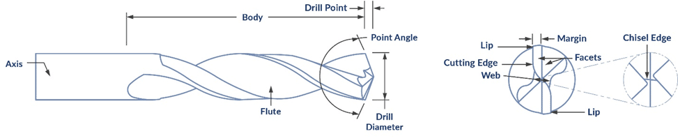
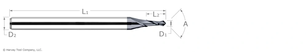
1.    Point Angle

This drill geometry refers to the angle of the cutting edge of the drill. As the point angle increases on a drill, the radial forces decrease, making the angle size a huge factor in what type of material the drill is optimized for and what types of applications should be run. The smaller the point angle, the better it will perform in through hole applications. This is because the smaller angle reduces the axial forces, allowing less of the chip to be pushed out and more cutting to occur.

118° & 120° Point Angle

Many machinists opt for this angle when machining soft gummy materials.

135° Point Angle

This point angle size is an excellent choice for machining aluminum and stainless steels.

140° Point Angle

This larger point angle size is great for machining steels.
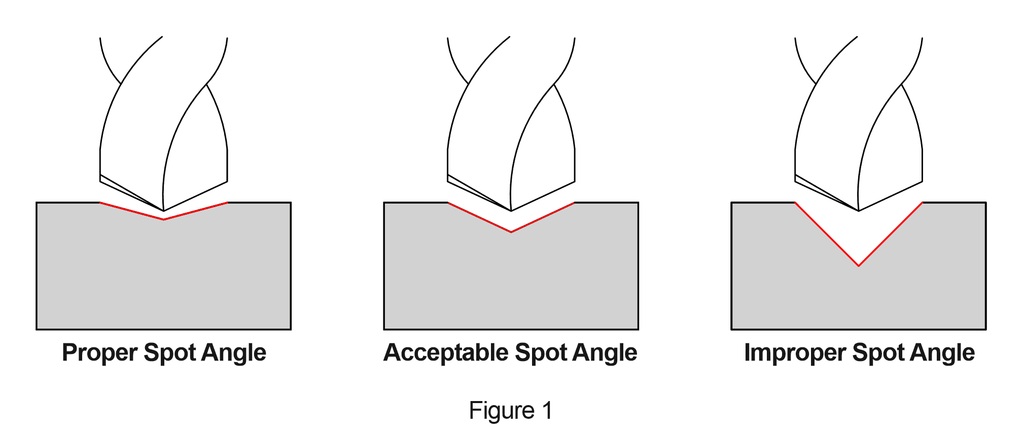
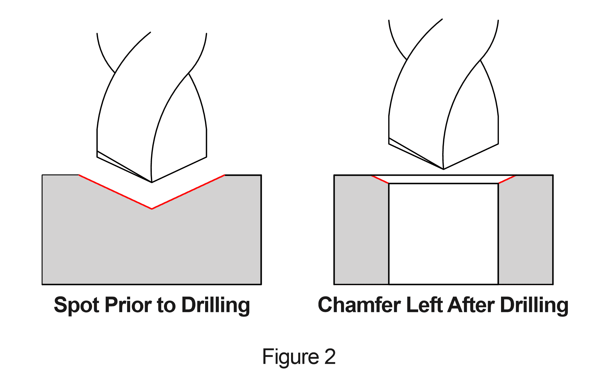
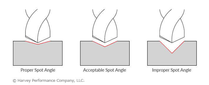
150° Point Angle

Large angles are often used for spot drilling applications, but the optimal spot drill angle is determined by the size of the angle of the final drill being used. Selecting the proper spot drill is essential to eliminating the chance of drill walking and ensuring a more accurate final product. Learn which spot angle should be used for your next drilling job in this in-depth guide.

2.    Chisel and Cutting Edges


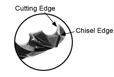
Although the chisel edge of a CNC drill does not provide any cutting action, it is responsible for the centering of the drill, as it extrudes the material towards the cutting edges. The cutting edges are then able to start the process of producing chips, which then travel up the flutes of the drill.
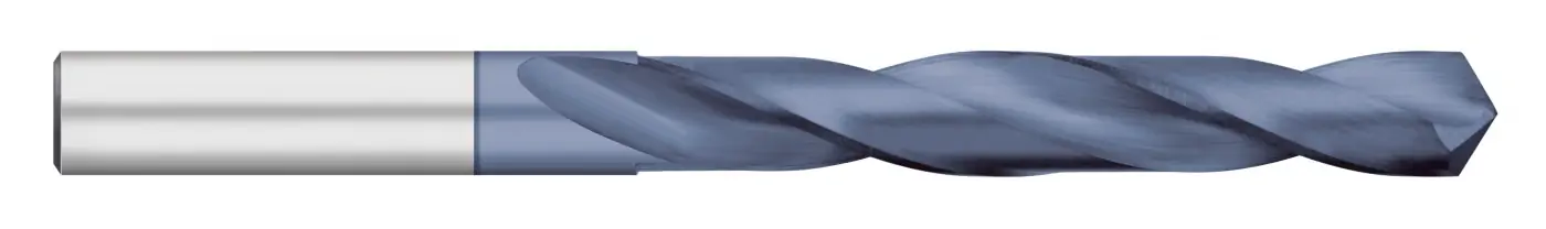
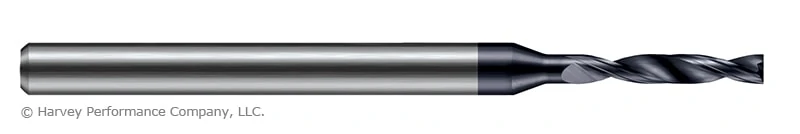
3.    Flutes

The most recognizable part of a drill is its flutes. They are the deep grooves that allow for chip evacuation to occur. When one thinks of a drill, they are likely imagining a spiral flute drill. These spiral flutes complement the point angle, chisel edge, and the cutting edges. They work like an elevator system to lift the chips out of the hole, allowing them to provide excellent chip evacuation. They work great in most material types and provide good hole quality.
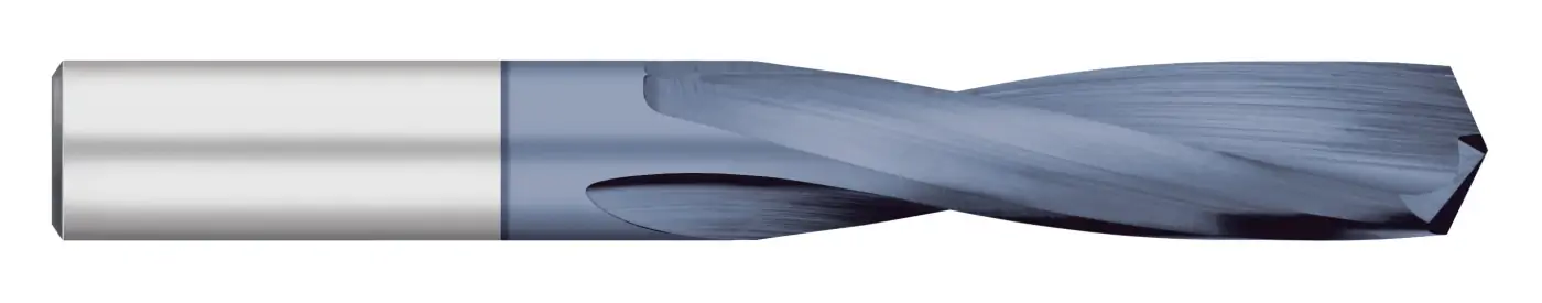
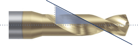
4.    Helix Angle

The helix angle is the angle formed by the leading edge of the land with a plane containing the axis of the drill. The main function of the helix angle is to transfer the chips out of the hole and a specific angle is relevant to the type of material that is being machined in and the particular application being run.
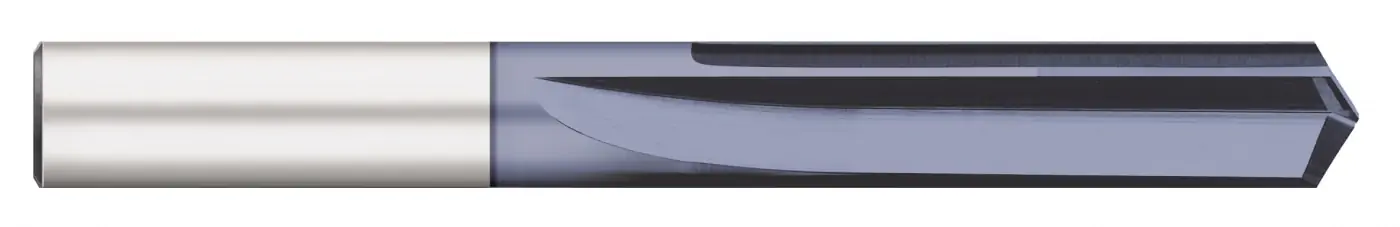
Low Helix

A low helix of 12° – 22° is recommended for materials like cast iron, brass, and hardened steels. In these “short chipping” materials, the chips move more freely, and the coolant provides enough assistance to properly evacuate the chips out of the hole.

Medium Helix

The most widely used helix angles are medium as they provide optimal chip evacuation and strength to the drill. Medium helix angles range from 28° – 32° and are recommended for any general purpose drilling applications.

High Helix

A high helix angle of 34° – 38° is recommended for long chipping material such as softer non-ferrous materials like brass, aluminum, and plastics. Drills with a high helix are also beneficial in deep hole applications as the chips can evacuate more easily.

5.    Web Thickness (Core)

The web is the core section of the drill body, which connects the two flutes. The thickness of the web determines the torsional strength of a drill. A drill with a larger web diameter will have more torsional strength than a drill with a smaller web diameter.

The proper web thickness is determined by the material type to be machined. Long chipping materials will require a drill with a smaller web thickness to provide adequate clearance for chip removal. When drilling short chipping materials such as cast iron, the drill web can be increased for additional strength.

6.    Corner Chamfer


A corner chamfer or radius is often added to eliminate the sharp edge at the intersection of the flutes and the outside diameter of a drill. This helps to eliminate material breakout when exiting a hole, while also helping to reduce the size of the entrance and exit burrs. This feature is also widely known to significantly extend tool life.
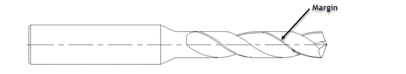
7.    Drill Margin

Margin(s) are the surfaces along the outer diameter of the drill which provide stability to the hole as they support the radial forces that are directed radially by the drill point.

Size of Drill Margin

The size of the margin will determine the overall quality of the hole. Wide marginswill stabilize the drill better, hold a tighter hole diameter tolerance, and improve the circularity of the hole. Narrow margins reduce friction and heat, eliminate work hardening, mitigate built-up edge, and provide better tool life.

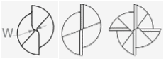
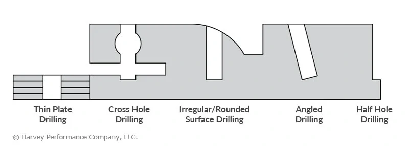
Number of Drill Margins

The number of margins on a drill is usually determined by the type of hole being machined. Single margin drills are very common in non-interrupted holes. Double or triple margin drills are common in interrupted or intersecting holes. The more margins there are, the better the guidance is to help the drill stay straight through interrupted cuts, cross holes, and irregular or angled surfaces on exit. While adding margins does provide these benefits for irregular style cuts, they also increase friction, which causes the drill to produce more heat. This causes wear to be accelerated, reducing the life of the tool.
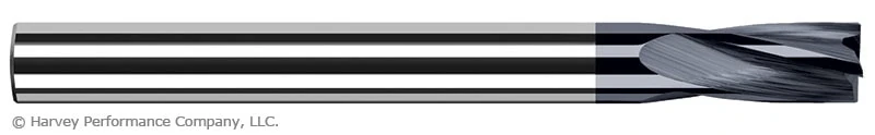
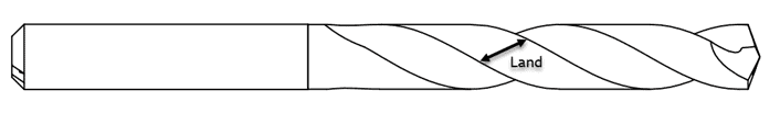
8.    Land of a Drill

The land is the outer portion of the body of the drill between two adjacent flutes. Land width will determine how much torsional force a drill can withstand before catastrophic failure. The smaller the land is, the more chip space there is, producing less torsional strength. The larger the land is, the less chip space there is, providing more torsional strength.

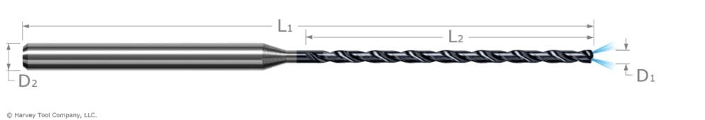
9.    Coolant-Through Channels


Not only do coolant-through channels offer any drilling application a multitude of benefits, but they are also highly recommended for hole depths that exceed 4XD (4 times diameter). Coolant-Through Drills allow for higher speed and feed rate capabilities, increased lubricity, better chip control, improved surface finish, and enhanced tool life.

10.  Shank

The shank is a very important yet overlooked drill geometry as it is the drive mechanism and is what is mounted into a Tool Holder. It is essential that the shank is held to proper diameter tolerance and considerations are being made depending on the holder being used. For example, a shank with an h6 tolerance is essential when a shrink fit style tool holder is being used.

Learning the different geometries of a CNC drill can greatly assist you in ensuring you are selecting the right drill for your next job, while understanding the functions of these features will allow you to trouble shoot any potential machining hiccups you may encounter in your future CNC drilling applications.

3 Tips for Avoiding Misaligned Holes


One of the most common issues machinists face during a drilling operation is hole misalignment. Hole alignment is an essential step in any assembly or while mating cylindrical parts. When holes are properly aligned, the mating parts fit easily in each other. When one of the pieces to the puzzle is inaccurate, however, machinists run into issues and parts can be scrapped. The two types of common misalignment woes are Angular Misalignment and Offset Misalignment.

Angular Misalignment

Angular misalignment is the difference in slope of the centerlines of the holes. When the centerlines are not parallel, a shaft will not be able to fit through the hole properly.

Offset Misalignment

Offset misalignment is the distance between the centerlines of the hole. This is the position of the hole from its true position or mating part. Many CAD software programs will help to identify if holes are misaligned, but proper technique is still paramount to creating perfect holes.

1.    Utilize a Spotting Drill

Using a spotting drill is a common way to eliminate the chance of the drill walking when it makes contact with the material. A spotting drill is designed to mark a precise location for a drill to follow, minimizing the drill’s ability to walk from a specific area.

valor holemaking high performance spotting drill

Valor Holemaking High Performance Spotting Drill

Although using a spotting drill would require an additional tool change during a job, the time spent in a tool change is far less than the time required to redo a project due to a misaligned hole. A misaligned hole can result in scrapping the entire part, costing time and money.

Do you know how to choose the perfect spot drill angle? Learn how in this in-depth guide so you can eliminate the chance of drill walking and ensure a more accurate final product.

2.    Be Mindful of Web Thickness

A machinist should also consider the web thickness of the drill when experiencing hole misalignment. A drill’s web is the first part of the drill to make contact with the workpiece material.

Essentially, the web thickness is the same as the core diameter of an end mill. A larger core will provide a more rigid drill and a larger web. A larger web, however, can increase the risk of walking, and may contribute to hole misalignment. To overcome this machining dilemma, machinists will oftentimes choose to use a drill that has a thinned web.

Web Thinning

Also known as a split point drill, web thinning is a drill with a thinned web at the point, which helps to decrease thrust force and increase point accuracy. There are many different thinning methods, but the result allows a drill to have a thinner web at the point while having the benefit of a standard web through­out the rest of the drill body.

A thinner web will:

  1. Be less susceptible to walking
  2. Need less cutting resistance
  3. Create less cutting force

3.    Select a Material Specific Drill

Choosing a material specific drill is one of the easiest ways to avoid hole misalignment. A material specific drill design has geometries that will mitigate the specific challenges that each unique material presents. Further, material specific drills fea­ture tool coatings that are proven to succeed in the specific material a machinist is working in.

Valor Holemaking High Performance Drills for Steels and High Performance Drills for Aluminum

Spot Drilling: The First Step to Precision Drilling

Drilling an ultra-precise hole can be tough. Material behavior, surface irregularities, and drill point geometry can all be factors leading to inaccurate holes. A Spot Drill, if used properly, will eliminate the chance of drill walking and will help to ensure a more accurate final product.

Choosing a Spot Drill

Ideally, the center of a carbide drill should always be the first point to contact your part. Therefore, a spotting drill should have a slightly larger point angle than that of your drill. Common drill point angles range from 118° to 140° and larger. Shallower drill angles are better suited to harder materials like steels due to increased engagement on the cutting edges. Aluminums can also benefit from these shallower angles through increased drill life. While these drills wear less and more evenly, they are more prone to walking, therefore creating a need for a proper high performance spot drill in a shallow angle to best match the chosen drill.

Five Valor holemaking high performance spot drills displayed on top of a workpiece with a purple product packaging container in front

If a spotting drill with a smaller point angle than your drill is used, your drill may be damaged due to shock loading when the outer portion of its cutting surface contacts the workpiece before the center. Using a drill angle equal to the drill angle is also an acceptable situation. Figure 1 illustrates the desired effect. On the left, a drill is entering a previously drilled spot with a slightly larger angle than its point. On the right, a drill is approaching an area with an angle that is far too small for its point.

Proper Spot Angle Diagram

Marking Your Spot

A Spotting Drill’s purpose is to create a small divot to correctly locate the center of a drill when initiating a plunge. However, some machinists choose to use these tools for a different reason – using it to chamfer the top of drilled holes. By leaving a chamfer, screw heads sit flush with the part once inserted.

Spot Drill

What Happens if I Use a Spot Drill with an Improper Angle?

Using a larger angle drill will allow the drill to find the correct location by guiding the tip of the drill to the center. If the outer diameter of a carbide drill were to contact the workpiece first, the tool could chip. This would damage the workpiece and result in a defective tool. If the two flutes of the drill were slightly different from one another, one could come into contact before the other. This could lead to an inaccurate hole, and even counteract the purpose of spot drilling in the first place.

Avoiding CNC Drill Walking With a Spotting Drill

Few CNC machining applications demand precision like drilling. The diameter hole size, hole depth, part location, and finish are all important and provide little recourse if not up to specifications. That said, accuracy is paramount – and nothing leads to inaccurate final parts faster than drill walking, or the inadvertent straying from a drill’s intended location during the machining process. So how does drill walking occur, and how can one prevent it?

To understand drill walking, think about the act of striking a nail with a hammer, into a piece of wood. Firm contact to a sharp nail into an appropriate wood surface can result in an accurate, straight impact. But if other variables come into play – an uneven surface, a dull nail, an improper impact – that nail could enter a material at an angle, at an inaccurate location, or not at all. With CNC Drilling, the drill is obviously a critical element to a successful operation – a sharp, unworn cutting tool – when used properly, will go a long way toward an efficient and accurate final part.

To mitigate any variables working against you, such as an uneven part surface or a slightly used drill, a simple way to avoid “walking” is to utilize a Spotting Drill. This tool is engineered to leave a divot on the face of the part for a drill to engage during the holemaking process, keeping it properly aligned to avoid a drill from slipping off course.

When Won’t a Spot Drill Work for My Application?

When drilling into an extremely irregular surface, such as the side of a cylinder or an inclined plane, this tool may not be sufficient to keep holes in the correct position. For these applications, flat bottom versions or Flat Bottom Counterbores may be needed to creating accurate features.

Harvey tool spot drill zoomed in on the tip of the drill
Harvey Tool Spot Drill

Titan USA Carbide Drills: Jobber, Stub, & Straight Flutes

When navigating Titan USA’s offering of carbide drills, it is imperative to understand the key differences among the three carbide drill styles: Jobber Length, Stub Length, and Straight Flute Drills. The right drill for your application depends on, among other factors, the material you are working in, the job requirements, and the required accuracy.

PRO TIP:

Chip evacuation can be an obstacle for hole making. Pecking cycles can be used to aid in chip removal. Peck cycles are when the drill is brought in and out of the hole location, increasing depth each time until the desired depth is reached. However, pecking cycles should only be used when necessary; this process increases cycle time and subjects the tool to added wear from the repeated engaging and disengaging.

Jobber Length Drills

Titan USA jobber length drill

A carbide Jobber Length Drill is the standard general-purpose drill within Titan USA’s offering. It has a long flute length and an included angle of 118o. These drills are great for general purpose drilling where the tolerances are not as tight as the Stub Drill or Straight Flute Drill. Due to the length of these drills, however, they will be more affected by any lack of rigidity in the set up and can have higher runout, or straying from a desired location, during the drilling operation.

PRO TIP:

To achieve high accuracy and great finish, consider utilizing a Reamer. Reamers are designed to remove a finite amount of material but bring a hole to a very specific size. To do this, first drill 90% – 94% of the desired hole diameter with a Jobber Drill. After 90% – 94% of the material is removed, go in for a finishing pass with a Reamer. Reaming tools are highly accurate and leave a beautiful finish.

Stub Length Drills

Titan USA stub length drill

Titan USA carbide Stub Length Drills have a shorter flute length, wider included point angle, and a significant drop in helix angle, when compared to Jobber Length Drills. The shorter length and wider tip create for a more rigid tool and, in turn, more accurate holes. The stub drill is the best option when drilling with tight tolerances on shallower holes.

Straight Flute Drills

Titan USA straight flute drill

Carbide Straight Flute Drills have the smallest core of the three drill types mentioned within this post. Titan USA offers Straight Flute Drills with 2 flutes and a 140o included angle. These drills are designed for hole making in materials that create short chips. Materials in which the Straight Flute Drill typically performs best include cast aluminums and cast irons, as well as copper. In addition, this type of drill can work very well in high hardness materials, but the core diameter should first be adjusted to accommodate the increased hardness. For these difficult to machine materials, casting the part with a core hole and then opening it up with the Straight Flute is a great option. This removes some of the stress caused by chip removal and allows for the drill to do what it does best.

Chip removal can be more difficult in this style of carbide drill because the chips are not guided along a helix. With helix flutes, the motion of chip removal is mostly continuous from their initiation point, through the flute valleys, and finally out of the flute valleys. The helix creates a wedge which helps push the chips along, but the straight flute does not have that. It interrupts that natural turning motion created by the drill face which can affect chip evacuation. Due to the interruption in motion this type of drill is better suited for applications involving chips of smaller size.

PRO TIP:

Helix drills create multiple different forces on the part, which can create micro imperfections. The Straight Flute Drills do not create those forces, so the finish is much more consistent down to the micro level. The margins of the Straight Flute Drill also burnish the inside of the hole as they spin, which improves the finish as well. When comparing the Straight Flute Drill to a helix drill, the length of the overall contact point is much shorter in the Straight Flute Drill, and has less heat generation. The decreased heat will also reduce the probability of work hardening.

Selecting Your Perfect Titan USA Carbide Drill

Selecting the correct carbide drill for your application is a crucial step in hole making. The Jobber Drill is a great general-purpose drill and should be utilized in applications requiring long reach. The Stub Drill increases the rigidity with its shorter length of flute, allowing it to drill with higher accuracy. Applications which involve tight tolerances and more shallow holes can be done with the Stub Drill for high-quality results. Lastly, for difficult to machine and hard materials, the Straight Flute Drill is the perfect solution. When the core diameter and chip evacuation is properly addressed, the Straight Flute Drill produces beautifully consistent surface finish and extremely tight tolerances. Similarly, Titan USA offers its carbide drills in both an uncoated option, and AlTiN coating. Traditionally, uncoated tools are general purpose workhorses in a wide variety of materials both ferrous and non-ferrous. AlTiN or Aluminum Titanium Nitride is an enhanced coating specifically made for ferrous materials that extends tool life and performance across a wide range of steels and their alloys.

For more information on Titan USA Drills, and to view its full selection, click here.

Drill / End Mills: Drill Style vs. Mill Style

Drill / End Mills are one of the most versatile tools in a machinist’s arsenal. These tools can perform a number of different operations, freeing space on your carousel and improving cycle times by limiting the need for tool changes. These operations include:

  1. Drilling
  2. V-Grooving
  3. Milling
  4. Spot Drilling
  5. Chamfering

Shop Harvey Tool Dill/End Mills Today – Fully Stocked in Multiple Styles

The ability of the Drill / End Mill to cut along the angled tip as well as the outer diameter gives it the range of operations seen above and makes it an excellent multi-functional tool.

5 unique drill mill operations

Drill Style vs. Mill Style

The main difference between Drill / End Mill styles is the point geometry.  They are defined by how the flutes are designed on the end of the tool, using geometry typically seen on either an end mill or a drill.  While mill style tools follow the features of an end mill or chamfer mill, the drill style geometry uses an S-gash at the tip.  This lends strength to the tip of the tool, while giving it the ability to efficiently and accurately penetrate material axially.  While both styles are capable of OD milling, mill style tools will be better for chamfering operations, while drill style will excel in drilling.  The additional option of the Harvey Tool spiral tipped Drill / End Mill is an unprecedented design in the industry.  This tool combines end geometry taken from our helical flute chamfer cutters with a variable helix on the OD for enhanced performance. Versatility without sacrificing finish and optimal performance is the result.

graphic showcasing the tool face differences between and mill and drill mills
Left to Right: 2 Flute Drill Style End, 2 Flute Mill Style End, 4 Flute Mill Style End

Drill Mills: Tool Offering

Harvey Tool currently offers Drill / End Mills in a variety of styles that can perform in different combinations of machining applications:

Mill Style – 2 Flute

This tool is designed for chamfering, milling, drilling non-ferrous materials, and light duty spotting. Drilling and spotting operations are recommended only for tools with an included angle greater than 60°. This is a general rule for all drill mills with a 60° point. Harvey Tool stocks five different angles of 2 flute mill-style Drill / End Mills, which include 60°, 82°, 90°, 100° and 120°. They are offered with an AlTiN coating on all sizes as well as a TiB2 coating for cutting aluminum with a 60° and 90° angle.

harvey tool 2 flute mill style drill end mill

Mill Style – 4 Flute

4 flute mill-style Drill / End Mills have two flutes that come to center and two flutes that are cut back. This Drill / End Mill is designed for the same operations as the 2 flute style, but has a larger core in addition the higher flute count. The larger core gives the tool more strength and allows it to machine a harder range of materials. The additional flutes create more points of contact when machining, leading to better surface finish. AlTiN coating is offered on all 5 available angles (60°, 82°, 90°, 100°, and 120°) of this tool for great performance in a wide array of ferrous materials.

harvey tool 4 flute mill style drill mill

Drill Style – 2 Flute

This tool is specifically designed for the combination of milling, drilling, spotting and light duty chamfering applications in ferrous and non-ferrous materials. This line is offered with a 90°, 120°, and 140° included angle as well as AlTiN coating.

2 flute drill mills drill style

Helical Tip – 4 Flute

The Helically Tipped Drill / End Mill offers superior performance in chamfering, milling and light duty spotting operations. The spiral tip design allows for exceptional chip evacuation and surface finish. This combined with an OD variable helix design to reduce chatter and harmonics makes this a valuable tool in any machine shop. It is offered in 60°, 90°, and 120° included angles and comes standard with the latest generation AlTiN Nano coating that offers superior hardness and heat resistance.

Selecting the Right Harvey Tool Miniature Drill

Among Harvey Tool’s expansive holemaking solutions product offering are several different types of miniature drill options and their complements. Options range from Miniature Spotting Drills to Miniature High Performance Drills – Deep Hole – Coolant Through. But which tools are appropriate for the hole you aim to leave in your part? Which tool might your current carousel be missing, leaving efficiency and performance behind? Understanding how to properly fill your tool repertoire for your desired holemaking result is the first step toward achieving success.

Pre-Drilling Considerations

Miniature Spotting Drills

Depending on the depth of your desired machined hole and its tolerance mandates, as well as the surface of the machine you will be drilling, opting first for a Miniature Spotting Drill might be beneficial. This tool pinpoints the exact location of a hole to prevent common deep-hole drilling mishaps such as walking, or straying from a desired path. It can also help to promote accuracy in instances where there is an uneven part surface for first contact. Some machinists even use Spotting Drills to leave a chamfer on the top of a pre-drilled hole. For extremely irregular surfaces, however, such as the side of a cylinder or an inclined plane, a Flat Bottom Drill or Flat Bottom Counterbore may be needed to lessen these irregularities prior to the drilling process.

harvey tool miniature spotting drill with dimension callout marks

Tech Tip: When spotting a hole, the spot angle should be equal to or wider than the angle of your chosen miniature drill. Simply, the miniature drill tip should contact the part before its flute face does.

infographic showcasing proper spot angle for spot drilling in relation to drills included angle

Selecting the Right Miniature Drill

Harvey Tool stocks several different types of miniature drills, but which option is right for you, and how does each drill differ in geometry?

Miniature Drills

Harvey Tool Miniature Drills are popular for machinists seeking flexibility and versatility with their holemaking operation. Because this line of tooling is offered uncoated in sizes as small as .002” in diameter, machinists no longer need to compromise on precision to reach very micro sizes. Also, this line of tooling is designed for use in several different materials where specificity is not required.

harvey tool extended depth miniature drill

Miniature High Performance Drills – Deep Hole – Coolant Through

For situations in which chip evacuation may be difficult due to the drill depth, Harvey Tool’s Deep Hole – Coolant Through Miniature Drills might be your best option. The coolant delivery from the drill tip will help to flush chips from within a hole, and prevent heeling on the hole’s sides, even at depths up to 20 multiples of the drill diameter.

harvey tool miniature deep hole coolant through gun drill

Miniature High Performance Drills – Flat Bottom

Choose Miniature High Performance Flat Bottom Drills when drilling on inclined and rounded surfaces, or when aiming to leave a flat bottom on your hole. Also, when drilling intersecting holes, half holes, shoulders, or thin plates, its flat bottom tool geometry helps to promote accuracy and a clean finish.

harvey tool miniature flat bottom drill with dimension callouts

Miniature High Performance Drills – Aluminum Alloys

The line of High Performance Drills for Aluminum Alloys feature TiB2 coating, which has an extremely low affinity to Aluminum and thus will fend off built-up edge. Its special 3 flute design allows for maximum chip flow, hole accuracy, finish, and elevated speeds and feeds parameters in this easy-to-machine material.

miniature drill for aluminum from harvey tool with dimension callouts

Miniature High Performance Drills – Hardened Steels

Miniature High Performance Drills – Hardened Steels features a specialized flute shape for improved chip evacuation and maximum rigidity. Additionally, each drill is coated in AlTiN Nano coating for hardness, and heat resistance in materials 48 Rc to 68 Rc.

miniature drill for hardened steel with dimension callouts

Miniature High Performance Drills – Prehardened Steels

As temperatures rise during machining, the AlTiN coating featured on Harvey Tool’s Miniature High Performance Drills – Prehardened Steels creates an aluminum oxide layer which helps to reduce thermal conductivity of the tool and helps to promote heat transfer to the chip, as well as improve lubricity and heat resistance in ferrous materials.

miniature drill for prehardened steel with dimension callouts

Post-Drilling Considerations

Miniature Reamers

For many operations, drilling the actual hole is only the beginning of the job. Some parts may require an ultra-tight tolerance, for which a Miniature Reamer (tolerances of +.0000″/-.0002″ for uncoated and +.0002″/-.0000″ for AlTiN Coated) can be used to bring a hole to size. harvey tool straight flute miniature reamer with dimension callouts

Tech Tip: In order to maintain appropriate stock removal amounts based on the reamer size, a hole should be pre-drilled at a diameter that is 90-94 percent of the finished reamed hole diameter.

Flat Bottom Counterbores

Other operations may require a hole with a flat bottom to allow for a superior connection with another part. Flat Bottom Counterbores leave a flat profile and straighten misaligned holes. For more information on why to use a Flat Bottom Counterbore, read 10 Reasons to Use Flat Bottom Tools.

harvey tool flat bottom counterbores with dimension callouts

Key Next Steps

Now that you’re familiar with miniature drills and complementary holemaking tooling, you must now learn key ways to go about the job. Understanding the importance of pecking cycles, and using the correct approach, is vital for both the life of your tool and the end result on your part. Read this post’s complement “Choosing the Right Pecking Cycle Approach,” for more information on the approach that’s best for your application.

10 Reasons to Use Flat Bottom Tools

Flat bottom tools, or tools with flat bottom geometry, are useful in a variety of situations and operations that tools with typical cutting geometry are not. The standard characteristics of drills or end mills are useful for their primary functions, but make them unsuitable for certain purposes. When used correctly, the following flat bottom tools can make the difference between botched jobs and perfect parts.

Flat Bottom Drills

Flat Bottom Drill

Flat bottom drills are perfect for tricky drilling situations or for creating flat bottom holes without secondary finishing passes. Consider using these specialized drills for the operations below.

infographic showing 5 different Flat Bottom Drill Operations

Thin Plate Drilling

When drilling through holes in thin plates, pointed drills are likely to push some material out the exit hole and create underside burrs. Flat bottom drills are significantly less likely to experience this problem, as their flat bottom geometry generates more even downward forces.

Crosshole Drilling

When drilling a hole that crosses the path of another hole, it is important to avoid creating burrs, since they can be extremely difficult to remove in this kind of cross section. Unlike drills with points, flat bottom drills are designed to not create burrs on the other side of through holes.

Irregular/Rounded Surface Drilling

Flat bottom drills initially engage irregular surfaces with their outer edge. Compared to making first contact with a standard drill point, this makes them less susceptible to deflection or “walking” on inclined surfaces, and more capable of drilling straighter holes.

Angled Drilling

Even if the surface of a part is flat or regular, a pointed drill is susceptible to walking if it engages the part at an angle, known as angled or tilted drilling. For the same reason flat bottom drills are ideal for drilling on irregular surfaces, they are perfect for angled drilling.

Half Hole Drilling

When drilling a half hole on the edge of a part, the lack of material on either side of the drill makes the operation unstable In this situation, a pointed drill is susceptible to walking. A flat bottom drill makes contact with its entire cutting geometry, allowing for more versatility and stability when drilling half holes.

Flat Bottom Counterbores

Flat Bottom Counterbore

Flat bottom counterbores are an excellent choice when a flat bottom hole is needed and a tool without flat bottom geometry was used to create it. Keep some of these tools on hand to be prepared for the operations below.

infographic showcasing 5 different uses of flat bottom counterbores

Bore & Finish Drilled Holes

Drill geometry is designed first and foremost for factors like stability, rigidity, and chip evacuation. Some holes will need secondary finishing operations. Flat bottom counterbores are often designed with a slow helix and low rake, which help them avoid part engagement and control finish.

Straighten Misaligned Holes

Even experienced machinists may drill a less-than-perfectly-straight hole or two in new and unfamiliar jobs. Fortunately, flat bottom counterbores are well-suited for straightening misaligned holes.

Spot Face & Counterbore on Irregular Surfaces

The unique geometry of flat bottom counterbores makes them  effective at spotting on irregular surfaces. Standard drills and spot drills are susceptible to walking on these kinds of surfaces, which can potentially ruin an operation.

Remove Drill Points

When a standard drill creates a hole (other than a through hole) it leaves a “drill point” at the bottom due to its pointed geometry. This is fine for some holes, but holes in need of a flat bottom will need a secondary operation from a flat bottom counterbore to remove the drill point.

Remove End Mill Dish

The dish angle present on most standard end mills allows proper end cutting characteristics and reduces full diameter contact. However, these end mills will naturally leave a small dish at the bottom of a hole created by a plunging operation. As with drill points, flat bottom counterbores are perfect to even out the bottom of a hole.