How to Advance Your Machining Career: 8 Tips From Machining Pros
Since we began shining a light on Harvey Performance Company brand customers via “In the Loupe’s,” Featured Customer posts, more than 20 machinists have been asked to share insight relevant to how they’ve achieved success in advancing their machining career. Each Featured Customer post includes interesting and useful information on a variety of machining-related subjects, including prototyping ideas, expanding a business, getting into machining, advantages and disadvantages of utilizing different milling machine types, and more. This post compiles 8 useful tips from our Featured Customers on ways to advance your machining career.
Tip 1: Be Persistent – Getting Your Foot in the Door is Half the Battle
With machining technology advancing at the amazing rate that it is, there is no better time to become a machinist. It is a trade that is constantly improving, and offers so many opportunities for young people. Eddie Casanueva of Nueva Precision first got into machining when he was in college, taking a job at an on-campus research center for manufacturing systems to support himself.
“The research center had all the workings of a machine shop,” Eddie said. “There were CNC mills, lathes, injection molding machines, and more. It just looked awesome. I managed to get hired for a job at minimum wage sweeping the shop floor and helping out where I could.
As a curious student, I would ask a million questions… John – an expert machinist – took me under his wing and taught me lots of stuff about machining. I started buying tools and building out my toolbox with him for a while, absorbing everything that I could.”
One of the best things about becoming a machinist is that there is a fairly low entry barrier. Many machinists start working right out of high school, with 12-18 months of on-the-job training or a one to two year apprenticeship. Nearly 70% of the machinist workforce is over the age of 45. The Bureau of Labor Statistics is predicting a 10% increase in the machinist workforce with opportunities for 29,000 additional skilled machinists by 2024, so it is certainly a great time to get your foot in the door.
Tip 2: Keep an Open Mind – If You Can Think of It, You Can Machine It
Being open-minded is crucial to becoming the best machinist you can be. By keeping an open mind, Oklahoma City-based company Okluma’s owner Jeff Sapp has quickly earned a reputation for his product as one of the best built and most reliable flashlights on the market today. Jeff’s idea for Okluma came to him while riding his motorcycle across the country.
“I had purchased what I thought was a nice flashlight for $50 to carry with me on the trip. However, two days in to the trip the flashlight broke. Of course, it was dark and I was in the middle of nowhere trying to work on my bike. I’m happy to pay for good tools, but that wasn’t what happened. Not only was there no warranty for replacement, there was no way to fix it. It was just made to be thrown away. That whole attitude makes me angry. When I got home, I decided I was going to put my new skills to work and design and build my own flashlight, with the goal of never running into an issue like I had on my trip ever again. I started by making one for myself, then four, then twenty. That was four years ago. Now I have my own business with one employee and two dogs, and we stay very busy.”
An awesome side benefit to working as a machinist is that you have all the resources to create anything you can dream of, like Jeff did with Okluma.
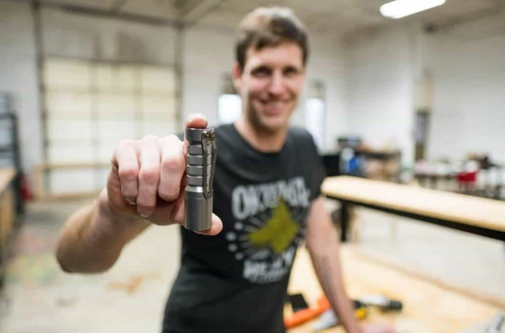
Image courtesy of Okluma.
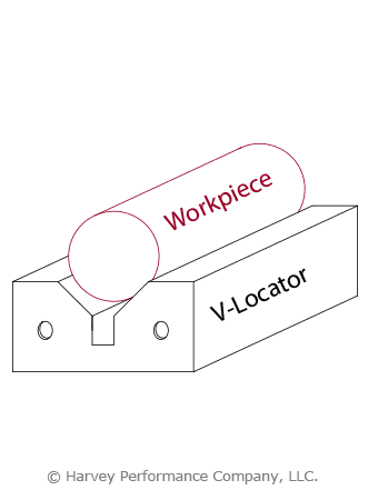
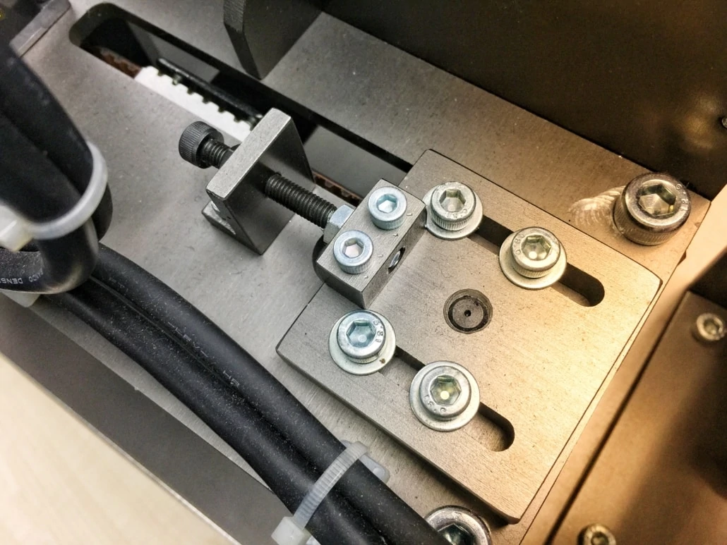
Tip 3: Be Patient – Take Time to Ensure Your Job is Setup Correctly before Beginning
The setup process is a huge part of machining, but is often overlooked. Alex Madsen, co- owner of M5 Micro in Minnesota, has been working in manufacturing for more than 11 years. Alex is also a part owner of World Fabrication, and owns his own job shop called Madsen Machine and Design. Alex has spent countless hours perfecting his setup to improve his part times.
“It is certainly challenging to use little tools, but the key is to not get discouraged. You should plan on lots of trial and error; breaking tools is just a part of the game. You may buy ten end mills and break six, but once you dial one in it will last the rest of the job.
You should also make sure to put extra time and effort into understanding your machine when working on micromachining jobs. You need to know where there is any backlash or issues with the machine because with a tiny tool, even an extra .0003” cut can mean the end of your tool. When a difference of one tenth can make or break your job, you need to take your time and be extra careful with your machine, tool inspection, and programming before you hit run.”
Tip 4: Effort Pays Off In Your Machining Career – Long Hours Result in Shop Growth
Success isn’t earned overnight. That is especially true in the machining world. Becoming a good machinist takes a great deal of sacrifice, says Josh from Fleet Machine Co. in Gloucester, MA.
“Opening your own shop involves more than learning how to program and machine. You also need to be willing to sacrifice some of your free time by working long hours to build your business from the ground up. Being a great machinist is important, but you also need to understand the basics of business, and you need to be able to sell your service and maintain a certain level of quality to keep your customers coming back.”
Working hard is a common theme we hear from our featured customers. Brothers Geordan and Nace Roberts of Master Machine Manufacturing have similar advice.
“We often need to work odd hours of the day to maintain the business, but we do it in a way that makes sure we have our family time. There are many times where we will go home, have dinner and hang out with the family, and wait until they are all sleeping to go back to work until two or three a.m. We will get back home later that morning to sleep a little and have breakfast with the family and send them on their way before heading back into the shop.” Starting and growing a business takes time. Every machinist starts from the beginning and through hard work and determination, grows their business.
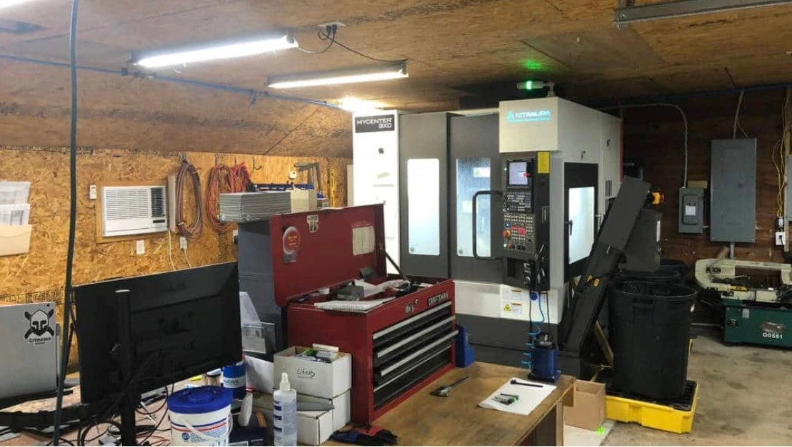
Image courtesy of Liberty Machine Inc.
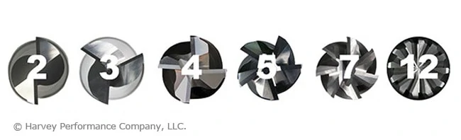
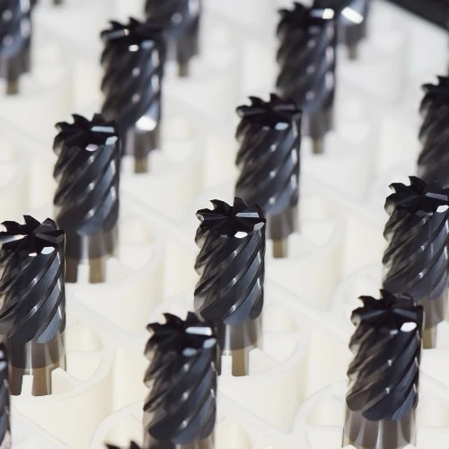
Tip 5: Utilize Tooling from Quality Manufacturers – All Tooling Isn’t Created Equal
When it comes down to it, tooling is singlehandedly the biggest choice you will make in your machining career. Grant Hughson, manufacturing engineer at Weiss Watch Company who works as a manufacturing instructor in his spare time, reflected on the importance of tooling.
“Tool to tool accuracy and performance is vital in this business, especially with our extremely tight tolerances. High quality tools make sure that we get the same performance time after time without needing to scrap parts. This saves us valuable time and money.”
While opting for cheaper tooling can appear to be beneficial when just starting out, before long, machinists are losing time and money because of unpredictability. Jonathan from TL Technologies echoed this point, saying:
“We feel that if we invested so much in these high-end machining centers, it would be criminal to put insufficient tooling and holders into them. We found that by selecting the proper tool with the appropriate sciences behind it we have been able to create products with a cost per cut that is not only competitive, but required to stay current. By keeping the quality as high as possible on the part making side of things, we’ve insured as much ease and reliability into our downstream process as we could. Quality tooling also provides predictability and added safety into the workflow. High-quality carbide tooling is the lifeblood of the business.”
Additional Thoughts Regarding Boosting Your Machining Career With Tooling:
Don’t Cheap Out
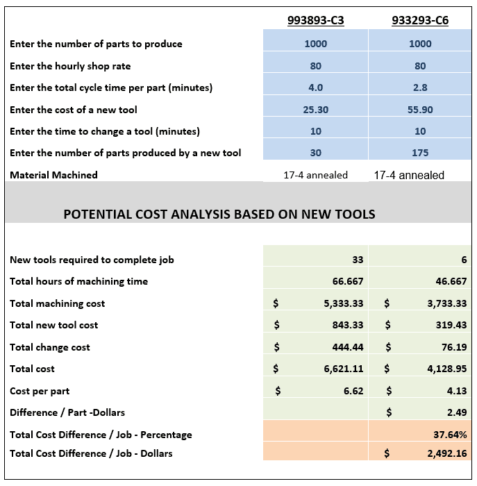
- “The additional cost is always worth the payoff in the end knowing that you have a tool that will produce quality parts and shave valuable minutes off your cycle times. The slightly higher cost of the Harvey/Helical product is small change compared to the long term cost savings associated with their performance” – Seth, Liberty Machine
Consistency is Key
- “We know the performance we are going to get from the tools is consistent, and we can always rely on getting immaculate finishes. While using the Harvey Tool and Helical product, we can confidently walk away from the machine and come back to a quality finished part every time.” – Bennett, RIT Baja SAE
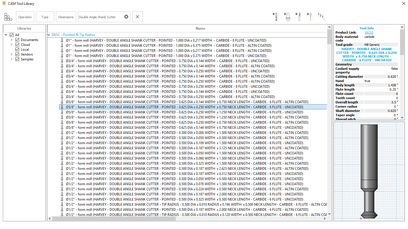
Superior Specialty Tools
- “One of the greatest things that I’ve experienced over the past year and a half is flexibility. We’ve asked for some specific tools to be made typically, the lead times that we found were beyond what we needed. We went through the Helical specials division and had them built within a couple of weeks. That was a game changer for us.” – Tom, John Force Racing
“Having high quality tooling like Helical is essential. Helical tools help us maintain a much higher machining efficiency because of the outstanding tool life, while also achieving more aggressive run times. In addition, we are able to consistently keep high tolerances, resulting in a better final product.” – Cameron, Koenig Knives
Tip 6: Get With the Times – Join the Social Media Community
Social media is a valuable tool for machinists. With ever-increasing popularity in networks such as Facebook, LinkedIn, Twitter, and Instagram, there will always be an audience to showcase new and unique products to. We asked a few of our featured customers how they incorporated social media into their machining career and the benefits that come along with it.
“A lot of our sales come through Instagram or Facebook, so I would recommend those platforms to anyone who is trying to start a business,” Jeff from Okluma said. “We have also had a lot of success collaborating with others in the community. Typically it is something we couldn’t do ourselves, or they couldn’t do themselves, so we share the labor and collaborate on some really cool items.”
Tip 7: Value Your Customers – Always Put Them First
“In the Loupe’s” featured customers repeatedly emphasized the importance of putting customers first. It’s a simple concept to master, and pays off immensely as you advance in your machining career. Repeat customers tell you that you are doing something right, said Brian Ross, owner of Form Factory.
“We have kept our customers happy and consistently deliver parts on time, so we get a lot of repeat business. Word definitely gets around on how you treat people so we try to treat everyone with respect and honesty which is key to running a good business.” Jeff from Okluma takes great pride in his customer service, saying “we only sell direct to consumers through our website so we can control our lifetime warranty. It has worked really well for us so far, so we have no plans to change that right now. I care more about our customers than any retailer is able to.”
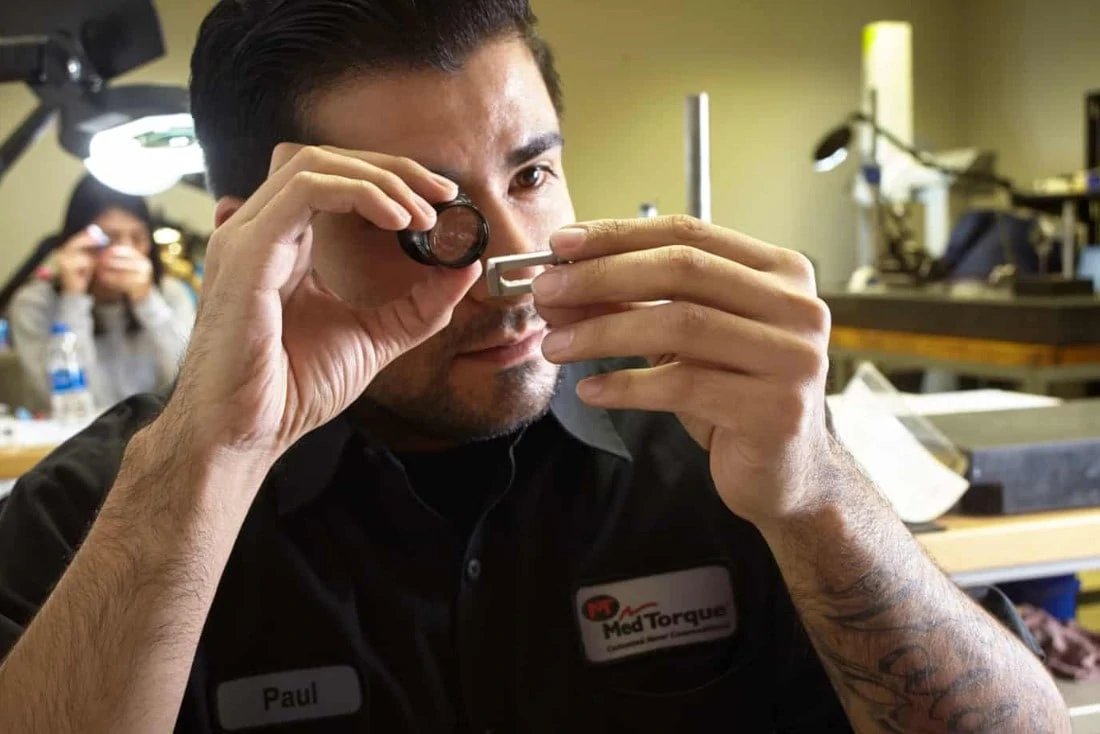
Image courtesy of MedTorque.
Tip 8: Never Stop Learning – Ask Questions Whenever You Can as Your Machining Career Advances
Hopefully some of these tips from our featured customers stuck with you in exploring a machining career. To leave you with a quote from of Seth Madore, owner of Liberty Machine, “Don’t stop learning. Keep your ears open and your mouth shut,” “That old guy in the shop has likely forgotten more than you will ever learn. The amount of tools in your Kennedy box doesn’t mean you’re a good machinist. Some of the best toolmakers I knew had small boxes with only the common tools. Learn how to excel with limited resources. Ask questions, and own up to your mistakes.”