This website www.harveyperformance.com/in-the-loupe/category/tool-selection/page/6/ is currently offline. Cloudflare's Always Online™ shows a snapshot of this web page from the Internet Archive's Wayback Machine. To check for the live version, click Refresh.
In today’s manufacturing industry, the reach necessary for many complex parts is pushing the boundaries of plausibility. Deep cavities and complex side milling operations are typical to the mold, tool, and die industry but are also quite common in many machining applications requiring angled walls. Fortunately, many long reach applications include angled walls extending into deep pockets and mold cavities. These slight angles afford machinists the opportunity to gain the necessary strength of tapered reach tool designs.
Increased Tool Performance & Productivity
The benefits of tapered end mills become clear when considering the increase in cross-sectional area compared to tools with straight reaches. Generally speaking, the larger a tool’s diameter is, the stronger it will be. A tool with a tapered neck will offer an increasing cross section, resulting in less tool deflection and increased strength over straight reach options.
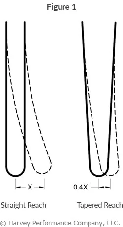
When considering an end mill with a straight reach versus the same end mill with a slightly tapered reach, there are clear gains in tool performance and productivity. With just a 3° angle per side, feed rates may be increased by an average of 10% over a straight neck. In long-run jobs, or long run-time operations, this can offer a significant reduction in production time and cost. The same 3° angle also affords a tool as much as 60% less deflection than a straight neck tool (Figure 1). A taper as small as half a degree also provides a 10% decrease in deflection even for shorter reaches. This reduction in deflection results in less chatter, better finish, and ultimately a higher quality product.
Tapered End Mills vs. Straight End Mills
Tapered Reach
Compared with straight reach end mills, tapered reach end mills have the following pros and cons:
• Reduced clearance • Not plausible for use in certain situations
Tapered Length of Cut
End mills with a tapered length of cut experience the following pros and cons when compared with end mills with a straight length of cut:
Pros:
• Easier to create flat tapered walls on 3-axis machines • Avoid witness marks caused by multiple passes with other tools • Better, more consistent finish
Cons:
• “Single-use” tools, suited only to specific wall angles • Inconsistent cutting diameter can complicate optimizing speeds and feeds
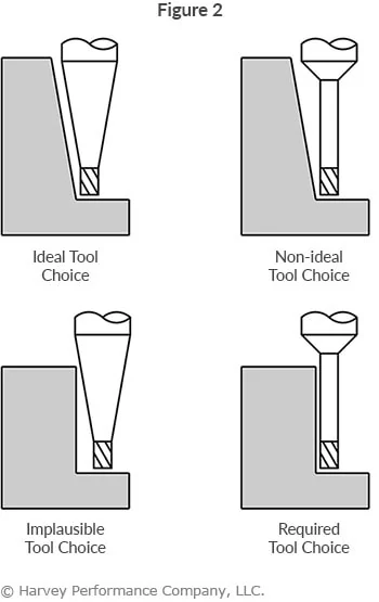
Despite the potential significant benefits of even a slight taper, it is important to note that tapered end mills are not a plausible choice for every job. Depending on the wall angle of your part, a tapered end mill can interfere with the work piece in situations where a straight tool would not. In Figure 2 below, the top two images show the ideal use of a tapered tool, while the bottom two images show when using a tapered end mill is implausible and a straight tool is necessary. Where clearances allow, an end mill with the largest possible tapered reach should be chosen for optimal tool performance.
Even a slight taper offers an increase in tool performance over the same tool with a straight neck. With added strength and reduced deflection, the benefits of a tapered end mill can be significant, and extend to a much broader range of industries and applications beyond just mold tool and die.
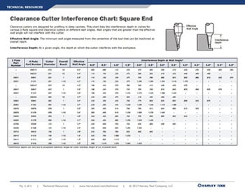
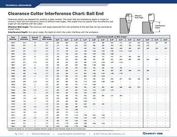
Tapered Reach Tooling Interference Charts
Where clearances allow, an end mill with the largest possible tapered reach angle should be chosen to allow for optimal tool performance. Refer to Harvey Tool’s interference charts for our Square and Ball clearance cutters to ensure that you pick the ideal tapered end mill based on the parameters of your operation.
https://www.harveyperformance.com/wp-content/uploads/2017/05/Feature-Image-Tapered-End-Mills-IMG.jpg5251400Tom Pylehttp://www.harveyperformance.com/wp-content/uploads/2018/08/Logo_HarveyPerformanceCompany-4.pngTom Pyle2017-05-30 16:00:562023-10-12 08:49:26Increase Productivity With Tapered End Mills
While they are specialty tools, dovetail style cutters have a broad range of applications. Dovetails are typically used to cut O-ring grooves in fluid and pressure devices, industrial slides and detailed undercutting work. Dovetail cutters have a trapezoidal shape—like the shape of a dove’s tail. General purpose dovetails are used to undercut or deburr features in a workpiece. O-ring dovetail cutters are held to specific standards to cut a groove that is wider at the bottom than the top. This trapezoidal groove shape is designed to hold the O-ring and keep it from being displaced.
The dovetail cutter’s design makes it fragile, finicky, and highly susceptible to failure. In calculating job specifications, machinists frequently treat dovetail cutters as larger than they really are because of their design, leading to unnecessary tool breakage. They mistake the tool’s larger end diameter as the critical dimension when in fact the smaller neck diameter is more important in making machining calculations.
As the tools are downsized for micro-applications, their unique shape requires special considerations. When machinists understand the true size of the tool, however, they can minimize breakage and optimize cycle time.
Miniature Matters – Micro Dovetailing
As the trend towards miniaturization continues, more dovetailing applications arise along with the need for applying the proper technique when dovetailing microscale parts and features. However, there are several common misunderstandings about the proper use of dovetails, which can lead to increased tool breakage and less-than-optimal cycle times.
There are seven common mistakes made when dovetailing and several strategies for avoiding them:
1. Not Taking Advantage of Drop Holes
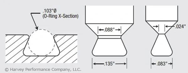
Many O-ring applications allow for a drop hole to insert the cutter into the groove. Take advantage of a drop hole if the part design allows it, as it will permit usage of the largest, most rigid tool possible, minimizing the chance of breakage (Figure 1).
Figure 1. These pictured tools are designed to mill a groove for a Parker Hannifin O-ring groove No. AS568A-102 (left). These O-rings have cross sections of 0.103″. There is a large variation in the tools’ neck diameters. The tool at right, with a neck diameter of 0.024″, is for applications without a drop hole, while the other tool, with a neck diameter of 0.088″, is for drop-hole applications. The drop-hole allowance allows application of the more rigid tool.
2. Misunderstanding a Dovetail’s True Neck Diameter.
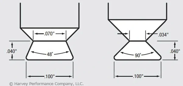
The dovetail’s profile includes a small neck diameter behind a larger end-cutting diameter. In addition, the flute runs through the neck, further reducing the tool’s core diameter. (In the example shown in Figure 2, this factor produces a core diameter of just 0.014″.) The net result is that an otherwise larger tool becomes more of a microtool. The torque generated by the larger diameter is, in effect, multiplied as it moves to the narrower neck diameter. You must remember that excess stress may be placed on the tool, leading to breakage. Furthermore, as the included angle of a dovetail increases, the neck diameter and core diameter are further reduced. O-ring dovetail cutters have an included angle of 48°. Another common included angle for general purpose dovetails is 90°. Figure 3 illustrates how two 0.100″-dia. dovetail tools have different neck diameters of 0.070″ vs. 0.034″ and different included angles of 48° vs. 90°.
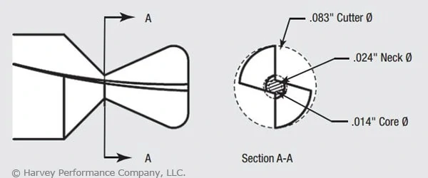
Figure 2. The dovetail tool pictured is the nondrop-hole example from Figure 1. The cross section illustrates the relationship between the end diameter of the tool (0.083″) and the significantly smaller core diameter (0.014″). Understanding this relationship and the effect of torque on a small core diameter is critical to developing appropriate dovetailing operating parameters.Figure 3: These dovetail tools have the same end diameter but different neck diameters (0.070″ vs. 0.034″) and different included angles (48° vs. 90°).
3. Calculating Speeds and Feeds from the Wrong Diameter.
Machinists frequently use the wrong tool diameter to calculate feed rates for dovetail cutters, increasing breakage. In micromachining applications where the margin for error is significantly reduced, calculating the feed on the wrong diameter can cause instantaneous tool failure. Due to the angular slope of a dovetail cutter’s profile, the tool has a variable diameter. While the larger end diameter is used for speed calculations, the smaller neck diameter should be used for feed calculations. This yields a smaller chip load per tooth. For example, a 0.083″-dia. tool cutting aluminum might have a chip load of approximately 0.00065 IPT, while a 0.024″-dia. mill cutting the same material might have a 0.0002-ipt chip load. This means the smaller tool has a chip load three times smaller than the larger tool, which requires a significantly different feed calculation.
4. Errors in Considering Depth of Cut.
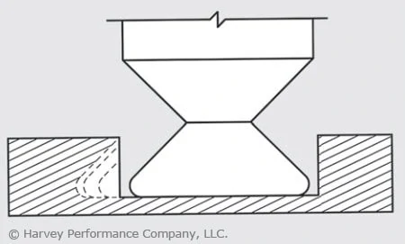
In micromachining applications, machinists must choose a depth of cut (DOC) that does not exceed the limits of the fragile tool. Typically, a square end mill roughs a slot and the dovetail cutter then removes the remaining triangular-shaped portion. As the dovetail is stepped over with each subsequent radial cut, the cutter’s engagement increases with each pass. A standard end mill allows for multiple passes by varying the axial DOC. However, a dovetail cutter has a fixed axial DOC, which allows changes to be made only to the radial DOC. Therefore, the size of each successive step-over must decrease to maintain a more consistent tool load and avoid tool breakage (Figure 4).
Figure 4: In microdovetailing operations, increased contact requires diminishing stepover to maintain constant tool load.
5. Failing to Climb Mill.
Although conventional milling has the benefit of gradually loading the tool, in low-chip load applications (as dictated by a dovetail cutter’s small neck diameter) the tool has a tendency to rub or push the workpiece as it enters the cut, creating chatter, deflection and premature cutting edge failure. The dovetail has a long cutting surface and tooth pressure becomes increasingly critical with each pass. Due to the low chip loads encountered in micromachining, this approach is even more critical to avoid rubbing. Although climb milling loads the tool faster than conventional milling, it allows the tool to cut more freely, providing less deflection, finer finish and longer cutting-edge life. As a result, climb milling is recommended when dovetailing.
6. Improper Chip Flushing.
Because dovetail cuts are typically made in a semi-enclosed profile, it is critical to flush chips from the cavity. In micro-dovetailing applications, chip packing and recutting due to poorly evacuated chips from a semi-enclosed profile will dull the cutter and lead to premature tool failure. In addition to cooling and lubricating, a high-pressure coolant effectively evacuates chips. However, excessive coolant pressure placed directly on the tool can cause tool vibration and deflection and even break a microtool before it touches the workpiece. Take care to provide adequate pressure to remove chips without putting undue pressure on the tool itself. Specific coolant pressure settings will depend upon the size of the groove, the tool size and the workpiece material. Also, a coolant nozzle on either side of the cutter cleans out the groove ahead of and behind the cutter. An air blast or vacuum hose could also effectively remove chips.
7. Giving the Job Away.
As discussed in item number 3, lower chip loads result in significantly lower material-removal rates, which ultimately increase cycle time. In the previous example, the chip load was three times smaller, which would increase cycle time by the same amount. Cycle time must be factored into your quote to ensure a profitable margin on the job. In addition to the important micro-dovetailing considerations discussed here, don’t forget to apply the basics critical to all tools. These include keeping runout low, using tools with application-specific coatings and ensuring setups are rigid. All of these considerations become more important in micro-applications because as tools get smaller, they become increasingly fragile, decreasing the margin of error. Understanding a dovetail cutter’s profile and calculating job specifications accordingly is critical to a successful operation. Doing so will help you reach your ultimate goal: bidding the job properly and optimizing cycle time without unnecessary breakage.
This article was written by Peter P. Jenkins of Harvey Tool Company, and it originally appeared in MicroManufacturing Magazine.
Harvey Tool’s Miniature High Performance Composite Drills are specifically designed with point geometry optimized for the unique properties of composite materials. Our Double Angle style is engineered to overcome common problems in layered composites and our Brad Point style is built to avoid the issues frequently experienced in fibrous composites.
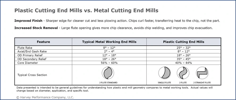
Many challenges can arise when machining different types of plastics. In the ever changing plastics industry, considerations for workholding, the melting point of your material, and any burrs that may potentially be created on the piece need to be examined prior to selecting a tool. Choosing the correct tool for your job and material is pivotal to avoid wasting time and money. Harvey Tool offers One, Two, and Three Flute Plastic Cutting End Mills with Upcut and Downcut Geometries. The following guide is intended to aid in the tool selection process to avoid common plastic cutting mistakes.
Choose Workholding Method
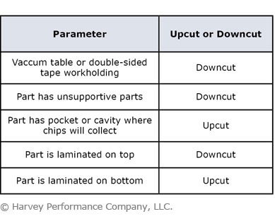
When it comes to workholding, not all plastic parts can be secured by clamps or vices. Depending on the material’s properties, these workholding options may damage or deform the part. To circumnavigate this, vacuum tables or other weaker holding forces, such as double sided tape, are frequently used. Since these workholdings do not secure the part as tightly, lifting can become a problem if the wrong tool is used.
Downcut Plastic Cutting End Mills — tools with a left hand spiral, right hand cut — have downward axial forces that push chips down, preventing lifting and delamination. If an Upcut Plastic Cutting End Mill is required, then a tool with minimal upward forces should be chosen. The slower the cutter’s helix, the less upward forces it will generate on the workpiece.
Determine Heat Tolerance
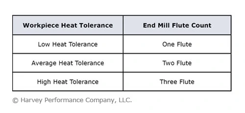
The amount of heat generated should always be considered prior to any machining processes, but this is especially the case while working in plastics. While machining plastics, heat must be removed from the contact area between the tool and the workpiece quickly and efficiently to avoid melting and chip welding.
If your plastic has a low melting point, a Single Flute Plastic Cutting End Mill is a good option. This tool has a larger flute valley than its two flute counterpart which allows for bigger chips. With a larger chip, more heat can be transferred away from the material without it melting.
For plastics with a higher heat tolerance, a Two or Three Flute Plastic Cutting End Mill can be utilized. Because it has more cutting edges and allows for higher removal rates, its tool life is extended.
Consider Finish Quality & Deburring
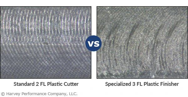
The polymer arrangement in plastics can cause many burrs if the proper tool is not selected. Parts that require hand-deburring offline after the machining process can drain shop resources. A sharp cutting edge is needed to ensure that the plastic is sheared cleanly, reducing the occurrence of burrs.Three Flute Plastic Cutting End Mills can reduce or eliminate the need to hand-deburr a part. These tools employ an improved cutting action and rigidity due to the higher flute count. Their specialized end geometry reduces the circular end marks that are left behind from traditional metal cutting end mills, leaving a cleaner finish with minimal burrs.
2 FLUTE PLASTIC CUTTER: A facing operation was performed in acrylic with a standard 2 Flute Plastic Cutting End Mill. The high rake, high relief design of the 2 flute tool increased chip removal rate, but also left distinct swirling patterns on the top of the workpiece.
3 FLUTE PLASTIC FINISHER: A facing operation was performed on a separate acrylic piece with a specialized 3 Flute Plastic Finisher End Mill. The specialized cutting end left minimal swirling marks and resulted in a smoother finish.
Identifying the potential problems of cutting a specific plastic is an important first step when choosing an appropriate plastic cutter. Deciding on the right tool can mean the difference between an excellent final product and a scrapped job. Harvey Tool’s team of technical engineers is available to help answer any questions you might have about selecting the appropriate Plastic Cutting End Mill.
https://www.harveyperformance.com/wp-content/uploads/2017/04/Feature-Image-Plastic-Cutter-Selection-IMG.jpg5251400Harvey Performance Companyhttp://www.harveyperformance.com/wp-content/uploads/2018/08/Logo_HarveyPerformanceCompany-4.pngHarvey Performance Company2017-04-07 08:31:562023-09-21 13:29:01Selecting the Right Plastic Cutting End Mill
We use cookies to ensure that we give you the best experience on our website. If you continue to use this site we will assume that you are happy with it.Ok