10 Reasons to Use Flat Bottom Tools
Flat bottom tools, or tools with flat bottom geometry, are useful in a variety of situations and operations that tools with typical cutting geometry are not. The standard characteristics of drills or end mills are useful for their primary functions, but make them unsuitable for certain purposes. When used correctly, the following flat bottom tools can make the difference between botched jobs and perfect parts.
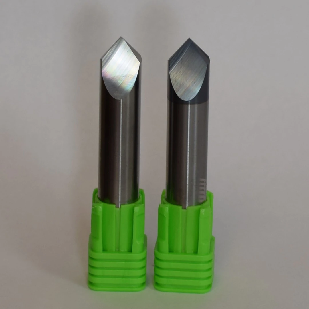
Flat Bottom Drills
Flat bottom drills are perfect for tricky drilling situations or for creating flat bottom holes without secondary finishing passes. Consider using these specialized drills for the operations below.
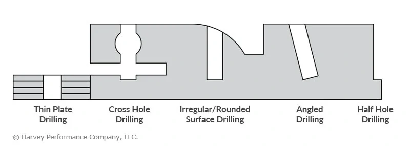
Thin Plate Drilling
When drilling through holes in thin plates, pointed drills are likely to push some material out the exit hole and create underside burrs. Flat bottom drills are significantly less likely to experience this problem, as their flat bottom geometry generates more even downward forces.
Crosshole Drilling
When drilling a hole that crosses the path of another hole, it is important to avoid creating burrs, since they can be extremely difficult to remove in this kind of cross section. Unlike drills with points, flat bottom drills are designed to not create burrs on the other side of through holes.
Irregular/Rounded Surface Drilling
Flat bottom drills initially engage irregular surfaces with their outer edge. Compared to making first contact with a standard drill point, this makes them less susceptible to deflection or “walking” on inclined surfaces, and more capable of drilling straighter holes.
Angled Drilling
Even if the surface of a part is flat or regular, a pointed drill is susceptible to walking if it engages the part at an angle, known as angled or tilted drilling. For the same reason flat bottom drills are ideal for drilling on irregular surfaces, they are perfect for angled drilling.
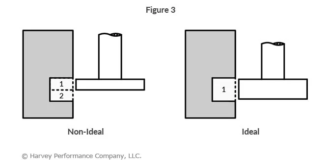
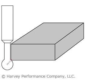
Half Hole Drilling
When drilling a half hole on the edge of a part, the lack of material on either side of the drill makes the operation unstable In this situation, a pointed drill is susceptible to walking. A flat bottom drill makes contact with its entire cutting geometry, allowing for more versatility and stability when drilling half holes.
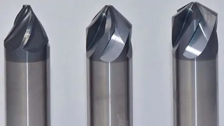
Flat Bottom Counterbores
Flat bottom counterbores are an excellent choice when a flat bottom hole is needed and a tool without flat bottom geometry was used to create it. Keep some of these tools on hand to be prepared for the operations below.
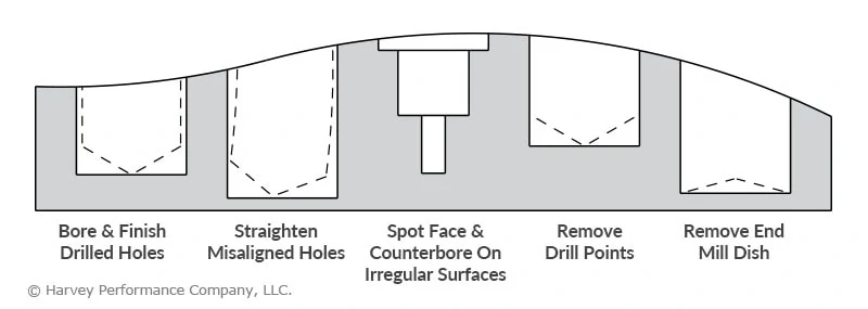
Bore & Finish Drilled Holes
Drill geometry is designed first and foremost for factors like stability, rigidity, and chip evacuation. Some holes will need secondary finishing operations. Flat bottom counterbores are often designed with a slow helix and low rake, which help them avoid part engagement and control finish.
Straighten Misaligned Holes
Even experienced machinists may drill a less-than-perfectly-straight hole or two in new and unfamiliar jobs. Fortunately, flat bottom counterbores are well-suited for straightening misaligned holes.
Spot Face & Counterbore on Irregular Surfaces
The unique geometry of flat bottom counterbores makes them effective at spotting on irregular surfaces. Standard drills and spot drills are susceptible to walking on these kinds of surfaces, which can potentially ruin an operation.
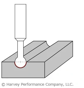
Remove Drill Points
When a standard drill creates a hole (other than a through hole) it leaves a “drill point” at the bottom due to its pointed geometry. This is fine for some holes, but holes in need of a flat bottom will need a secondary operation from a flat bottom counterbore to remove the drill point.
Remove End Mill Dish
The dish angle present on most standard end mills allows proper end cutting characteristics and reduces full diameter contact. However, these end mills will naturally leave a small dish at the bottom of a hole created by a plunging operation. As with drill points, flat bottom counterbores are perfect to even out the bottom of a hole.