This website www.harveyperformance.com/in-the-loupe/category/tool-selection/page/3/ is currently offline. Cloudflare's Always Online™ shows a snapshot of this web page from the Internet Archive's Wayback Machine. To check for the live version, click Refresh.
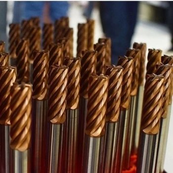
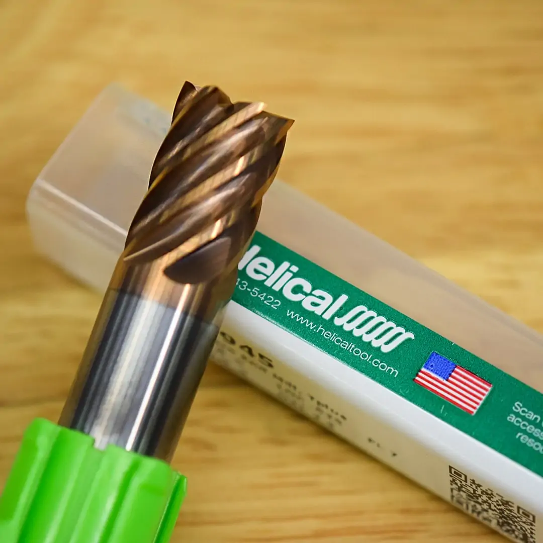
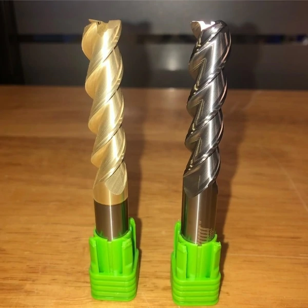
When working with difficult-to-machine materials, such as Inconel, stainless steel, or hardened steels, utilizing an effective coating is important for sustaining the life of your tool and perfecting the outcome of your part. While looking for the right coating, many machinists try out several before finding a solution that works – a process that wastes valuable time and money. One coating gaining popularity in applications involving tough materials is Helical Solutions’ Tplus coating. This post will explore what Tplus coating is (and isn’t), and when it might be best for your specific job.
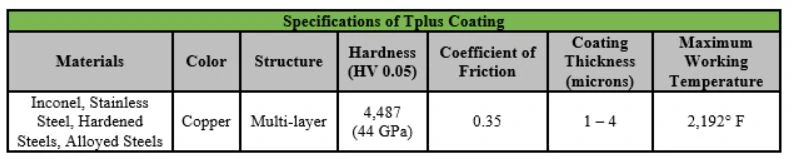
What is Helical Solutions’ Tplus Coating?
Helical’s Tplus coating is a Titanium-based, multi-layered coating that is applied by a Physical Vapor Deposition (PVD) process. This method of coating takes place in a near-vacuum and distributes micron-thick layers evenly onto a properly prepared tool. Tplus is a premium, multi-layered, titanium coating that increases edge strength, wear resistance, and tool life.
When Should a Machinist Use Tplus Coating?
When Working in Difficult to Machine Materials
Tplus coating works great in difficult-to-machine materials such as Inconel, stainless steel, hardened steels, and other alloyed steels with a hardness up to 65 Rc. It provides high hardness (44 GPa) for your tool, creating stronger cutting edges and resulting in extended tool life.
When Working in High Temperature Applications
When you are running an application in a ferrous material where extreme heat and work hardening are a possibility, Tplus is a great solution, as it’s designed to withstand high temperatures (up to 2,192°).
In the absence of coolant, fear not! Tplus coating is a viable option since it can handle the heat of machining. The low coefficient of friction (0.35) guarantees great performance in dry machining and allows the coated tool to move throughout the part smoothly, creating less heat, which is extremely beneficial in applications without coolant.
In Large Production Runs
In high production runs is truly where this coating excels, as its properties allow your tool to remain in the spindle longer – creating more parts by avoiding time in swapping out a worn tool.
https://www.harveyperformance.com/wp-content/uploads/2019/08/Feature-Image-Tplus-Coatings-IMG.jpg5251400Harvey Performance Companyhttp://www.harveyperformance.com/wp-content/uploads/2018/08/Logo_HarveyPerformanceCompany-4.pngHarvey Performance Company2019-08-05 01:39:432024-02-08 15:31:01An In-Depth Look at Helical’s Tplus Coating for End Mills
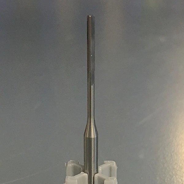
Most machinists are familiar with CNC drilling, but did you know that the common practice for holemaking is to always use a reamer? When done correctly, reaming can be a fast and highly accurate operation that results in precision holes.
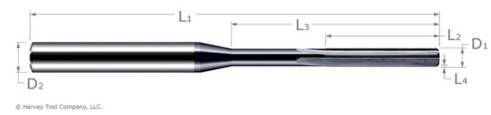
By examining a Harvey Tool Miniature Reamer and its critical dimensions, we can better understand the functionality of this useful tool. In the above image of a straight flute reamer, D1 references the reamer diameter, the specific size intended for your hole; and D2 points to the shank diameter. At Harvey Tool, reamer shanks are oversized to help maintain tool strength, stiffness, and accuracy. Shanks also have an h6 tolerance, which is crucial for high precision tool holders, such as heat shrink collets. Other critical dimensions of a reamer include its overall length (L1), margin length (L2), overall reach (L3), and chamfer length (L4).
Harvey Tool also offers Miniature Reamers – Right Hand Spiral. This tool is designed to leave a superior part finish and help with chip evacuation in blind hole applications.
The Functions of Miniature Reamers
Reamers Provide Precision – As mentioned earlier, reamers are great for machining precision hole diameters. To use a reamer properly, you must first have a pre-drilled hole that’s between 90% and 94% of the final hole diameter. For example, if you need a finished a hole of .220″, your predrilled hole should be somewhere between .1980″ and .2068″. This allows the tool to take enough material off to leave a great finish, but does not overwork it, potentially causing damage. The tolerance for uncoated reamers is +.0000″/-.0002″, while the tolerance for AlTiN coating is +.0002″/-.0000″. These tolerances provide you the peace of mind of knowing that your hole will meet exact specifications.
Achieve a Quality CNC Finish – When a high surface finish is required of a hole, reamers should always be used to reach the desired tolerance. Both the pre-drilled hole and the tool’s margin help to keep the reamer centered while cutting, leading to a better finish.
Minimize Machining Production Runs – For machine shops, consistency is a priority. This is especially true in production runs. The last thing a machinist wants to see is an oversized hole on a part they have already preformed many operations on. Remember, reamers have the benefit of offering consistent hole size, preventing an out of tolerance finish. These consistent holes lead to valuable time savings and reduced scrap costs.
CNC Machining Exotic Alloys: When machining Inconel, titanium, and other high-cost materials, reaming your hole is important to ensure that the desired finish specification is met. With reamers, a machinists can better predict tool life, leading to a better finished product and less scrap ratios. It is important to note that Harvey Tool reamers are offered AlTiN coated and fully stocked in every .0005” increment from .0080” to .0640”.
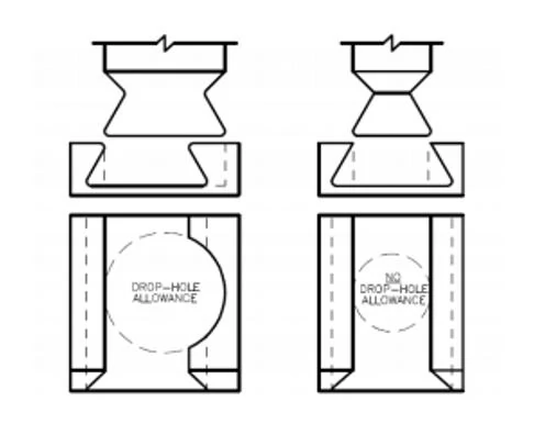
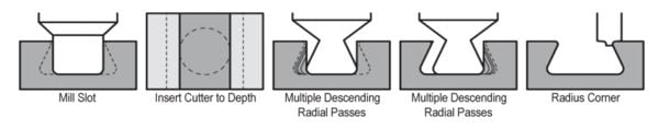
Dovetail Cutters are cutting tools that create a trapezoidal-type shape, or a dovetail groove, in a part. Due to the form of these tools, special considerations need to be made in order to achieve long tool life and superior results. This is particularly true when machining O-ring grooves, as this operation requires the tool to drop into the part to begin cutting. Using an appropriate tool entry method, specifically understanding when drop hole allowance is (and is not) needed, is important to keep common dovetail mishaps from occurring.
What is a Drop-Hole?
When designing parts featuring O-ring grooves, the consideration of drop-hole allowance is a pivotal first step. A drop-hole is an off-center hole milled during the roughing/slotting operation. This feature allows for a significantly larger, more rigid tool to be used. This is because the cutter no longer has to fit into the slot, but into a hole with a diameter larger than its cutter diameter.
Why consider adding a Drop-Hole?
When compared to tools without drop-hole allowance, tools with drop-hole allowance have a much larger neck diameter-to-cutter diameter ratio. This makes the drop-hole tools far stronger, permitting the tool to take heavy radial depths of cut and fewer step-overs. Using a drop-hole will allow the use of the stronger tool, which will increase production rate and improve tool life.
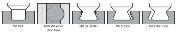
Machining Operation with Drop-Hole Allowance
A maximum of 4 radial passes per side are needed.
When Not to Drop Hole
Drop-holes are sometimes not permitted in a design due to the added stress concentration point it leaves. Common examples for where a drop-hole would not be allowed include:
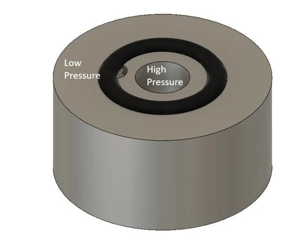
In high pressure applications
In seals requiring a high reliability
Where dangerous or hazardous fluids are being used
The issue with drop-hole allowance is that the additional clearance used for tool entry can create a weak spot in the seal, which can then become compromised under certain conditions. Ultimately, drop-hole allowance requires approval from the customer to ensure the application allows for it.
Machining Operation Without Drop-Hole Allowance
A maximum of 20 radial passes per side are needed.
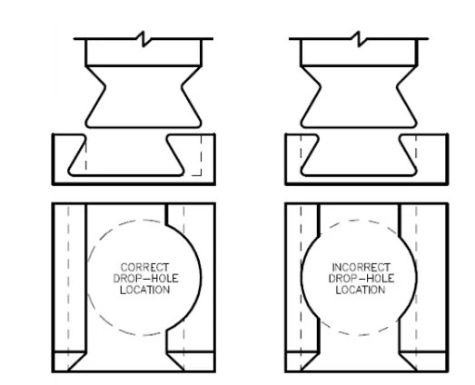
Drop-Hole Placement
When adding a drop-hole to your part, it is important to ensure that the feature is placed correctly to maximize seal integrity. Per the below figure, the drop-hole should be placed off center of the groove, ensuring that only one side of the groove is affected.
It is also necessary to ensure that drop-hole features are put on the correct side of the groove. Since O-rings are used as a seal between pressures, it is important to have the drop-hole bordering the high pressure zone. As pressure moves from high to low, the O-ring will be forced into the fully supported side, allowing for a proper seal (See image below).
https://www.harveyperformance.com/wp-content/uploads/2019/05/Feature-Image-Drop-Hole-Allowance-IMG-1.jpg5251400Harvey Performance Companyhttp://www.harveyperformance.com/wp-content/uploads/2018/08/Logo_HarveyPerformanceCompany-4.pngHarvey Performance Company2019-05-06 09:48:552023-10-24 10:53:22When to and Not to Use Drop Hole Allowance
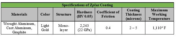
Non-ferrous and non-metallic materials are not usually considered difficult to machine, and therefore, machinists often overlook the use of tool coatings. But while these materials may not present the same machining difficulties as hardened steels and other ferrous materials, a coating can still vastly improve performance in non-ferrous applications. For instance, materials such as aluminum and graphite can cause machinists headaches because of the difficulty they often create from abrasion. To alleviate these issues in non-ferrous machining applications, a popular coating choice is Helical Solution’s Zplus coating.
What is Helical Solutions’ Zplus Coating?
Helical’s Zplus is a Zirconium Nitride-based coating, applied by a Physical Vapor Deposition (PVD) process. This method of coating takes place in a vacuum and forms layers only microns thick onto the properly prepared tool. Zirconium Nitride does not chemically react to a variety of non-ferrous metals, increasing the lubricity of the tool and aiding in chip evacuation.
When Should a Machinist Use Helical Solution’s Zplus?
Working with Abrasive Materials
While Zpluswas created initially for working in aluminum, its hardness level and maximum working temperature of 1,110°F enables it to work well in abrasive forms of other non-ferrous materials, as well. This coating decreases the coefficient of friction between the tool and the part, allowing it to move easier through more abrasive materials. This abrasion resistance decreases the rate of tool wear, prolonging tool life.
Concerns with Efficient Chip Evacuation
One of the primary functions of this coating is to increase the smoothness of the flutes of the tool, which allows for more efficient chip removal. By decreasing the amount of friction between the tool and the material, chips will not stick to the tool, helping to prevent chip packing. The increased lubricity and smoothness provided by the coating allows for a higher level of performance from the cutting tool. Zplus is also recommended for use in softer, gummy alloys, as the smooth surface encourages maximum lubricity within the material – this decreases the likelihood of those gummier chips sticking to the tool while machining.
Large Production Runs
Uncoated tools can work well in many forms of non-ferrous applications. However, to get a genuinely cost-effective tool for your job, the proper coating is highly recommended. Large production runs are known for putting a lot of wear and tear on tools due to their increased use, and by utilizing an appropriate coating, there can be a significant improvement in the tools working life.
When is Zplus Coating Not Beneficial to My Application?
Finishing Applications
When your parts finish is vital to its final application, a machinist may want to consider going with an uncoated tool. As with any coating, ZrN will leave a very minor rounded edge on the tip of the cutting edge. The best finish often requires an extremely sharp tool, and an uncoated tool will have a sharper cutting edge than its coated version.
https://www.harveyperformance.com/wp-content/uploads/2019/04/Feature-Image-Zplus-Coatings-IMG.jpg5251400Harvey Performance Companyhttp://www.harveyperformance.com/wp-content/uploads/2018/08/Logo_HarveyPerformanceCompany-4.pngHarvey Performance Company2019-04-01 03:17:542023-10-24 10:53:44What to Know About Helical Solution’s Zplus Coating
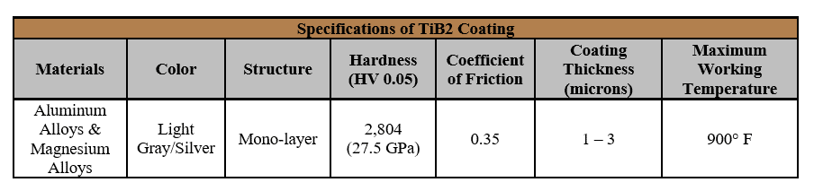
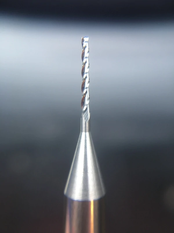
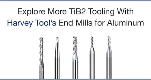
Aluminum and magnesium alloys are common materials found in machine shops worldwide, and are known as an “easier” material to machine. However, machinists can still experience hiccups while machining this material if they are not prepared with the proper tooling.. When working with aluminum and magnesium alloys, it is important to choose a coating that will work to extend your tool’s life and aid in the removal of chips. A popular choice for this material bucket is Harvey Tool’s TiB2 coating.
Harvey Tool’s TiB2 coating is a Titanium Diboride, ceramic-based coating that provides superb erosion resistance during machining. TiB2 is added to a tool by a method called Physical Vapor Deposition (PVD), which is conducted in a vacuum where particles are vaporized and applied onto a surface, forming thin layers of material onto the properly-prepped tool. This method enables the coating to be corrosion and tarnish resistant.
TiB2 is identified in Harvey Tool’s product catalog with a “-C8” following the sku number. It can be found offered in Harvey Tool’s lines of Variable Helix End Mills for Aluminum Alloys and Miniature High Performance Drills for Aluminum Alloys.
When Should a Machinist Use TiB2 Coating?
Chip Evacuation Concerns
TiB2 has an extremely low affinity to aluminum, which helps with the chip evacuation process. Simply, chips of a material are able to evacuate through chip valleys easier if they don’t have a high affinity to the coating being used. TiB2 coating does not chemically react with aluminum and magnesium, which allows for smoother chip evacuation, as the chips do not stick to the coating and create issues such as chip packing. This is a common machining mishap that can cause both part and tool damage, quickly derailing a machining operation. By using a coating that increases the lubricity of the tool, chips will not have a surface to stick to and will more smoothly evacuate from the flutes of the tool.
Large Production Runs
While an uncoated tool may work fine in some applications, not all applications can succeed without a tool coating. When working with large production runs where the tools need to hold up through the process of machining large numbers of parts, using a coating is always recommended because they extend the life of your tool.
When is TiB2 Coating Not Beneficial to My Application?
Extremely Abrasive Materials
During the PVD coating process, tools can reach a temperature in excess of 500° F, which can cause the toughness of the carbide to drop slightly. This process does not normally compromise the performance of the tool due to the coating being placed over the carbide. The coating then protects the slightly weakened edge and increases tool performance in recommended materials. Micro-fractures only start appearing when the tool is being run incredibly fast through highly abrasive materials, leading to a decrease in the life of the tool.
Extremely Soft Materials
The coating, while only a few microns thick at most, still provides an ever-so-slight rounded edge to the cutting edge of the tools it is placed on. It is important to take this into consideration, as using the sharpest tools possible when working with materials such as soft plastics is recommended. The sharpest edge possible decreases the likelihood of any “pushing” that might occur on the material and increases the likelihood of proper “shearing” when machining.
When Finish Is Vital
If your part’s finish is imperative to the final product, an uncoated tool may work better for your application. A coating, like stated above, creates a microscopic rounded surface to the cutting edge of the tool. When running tools at finishing speeds and feeds in materials like aluminum, a sharp edge can create the difference between a finished part that does – or does not – pass final inspection.
https://www.harveyperformance.com/wp-content/uploads/2019/03/Feature-Image-TiB2-Coatings-IMG-1.jpg5251400Harvey Performance Companyhttp://www.harveyperformance.com/wp-content/uploads/2018/08/Logo_HarveyPerformanceCompany-4.pngHarvey Performance Company2019-03-08 09:14:352023-10-24 10:54:05What to Know About Harvey Tool’s TiB2 Coating
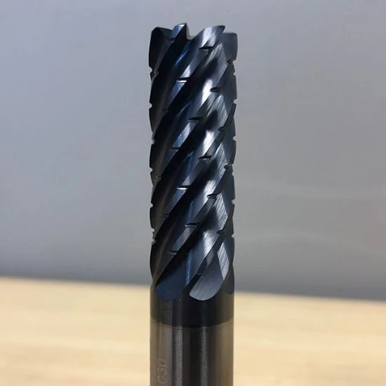
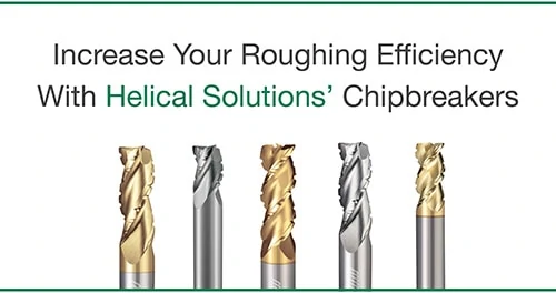
Knuckle Roughers and Chipbreakers are common profiles found on roughing end mills that, while fairly similar in appearance, actually serve different functions. Chipbreakers refer to the notches along the cutting edge of a tool that work to break up chips to prevent common evacuation mishaps. Knuckle Roughers refer to the serrated cutting edge of a tool, which works to enhance cutting action for an overall smoother operation.
Determining the appropriate style of tool is a very important first step to a successful roughing application.
To aid chip evacuation, Chipbreaker End Mills feature a notched profile along the cutting edge that break down long chips into smaller, more manageable pieces. These tools are often utilized in aluminum jobs, as long, stringy chips are common with that material.
Each notch is offset flute-to-flute to enhance the surface finish on the part. This works by ensuring that as each flute rotates and impacts a part, following flutes work to clean up any marks or extra material that was left behind by the first pass. This leaves a semi-finished surface on your part.
In addition to improving chip control and reducing cutting resistance, these tools also help in decreasing heat load within the chips. This delays tool wear along the cutting edge and improves cutting performance. Not only are these tools great for hogging out a great deal of material, but they can be utilized in a wide array of jobs – from aluminum to steels. Further, a machinist can take full advantage of the unique benefits this tool possesses by utilizing High Efficiency Milling toolpaths, meant to promote efficiency and boost tool life.
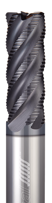
Knuckle Roughers
Knuckle Rougher End Mills have a serrated cutting edge that generates significantly smaller chips than a standard end mill cutting edge. This allows for smoother machining and a more efficient metal removal process, similar to Chipbreaker End Mills. However, the serrations chop the chips down to much finer sizes, which allows more chips into the flutes during the evacuation process without any packing occurring.
Designed for steels, Knuckle Rougher End Mills are built to withstand harder materials and feature a large core. Because of this, these tools are great for roughing out a lot of material. However, due to the profile on the cutting edge, tracks along the wall can sometimes be left on a part. If finish is a concern, be sure to come in with a finishing tool after the roughing operation. Knuckle Roughers have proven the ability to run at higher chip loads, compared to similar end mills, which makes this a highly desired style for roughing. Further, this style of rougher causes a lot of heat and friction within the chips, so it’s important to run flood coolant when running this tool.
Key Differences Between Knuckle Roughers & Chipbreakers
While the two geometries offer similar benefits, it’s important to understand the distinct differences between them. Chipbreakers feature offset notches, which help to leave an acceptable finish on the walls of a part. Simply, the material left on an initial flute pass is removed by subsequent passes. A Knuckle Rougher does not feature this offset geometry, which can leave track marks on your part. Where part finish is of upmost importance, utilize a Knuckle Rougher to first hog out a great deal of steel, and work a final pass with a Finishing End Mill.
A unique benefit of Knuckle Roughers is the grind they possess – a cylindrical grind, compared to a relieved grind of a Chipbreaker End Mill. Because of this, Knuckle Roughers are easier to resharpen. Therefore, instead of buying a new tool, resharpening this profile is often a cheaper alternative.
https://www.harveyperformance.com/wp-content/uploads/2019/02/Feature-Image-Chipbreakers-vs-Knuckle-Roughers-IMG.jpg5251400Allyn Hoodhttp://www.harveyperformance.com/wp-content/uploads/2018/08/Logo_HarveyPerformanceCompany-4.pngAllyn Hood2019-02-15 11:31:552023-10-24 10:54:38Chipbreaker vs. Knuckle Rougher End Mills
A machinist is faced with many questions while selecting the proper tool for their job. One key decision that must be made is whether a material specific tool is appropriate and necessary for the application that’s going to be performed – whether the benefits of using this type of tool outweigh the higher price tag than that of a tool designed for use in a variety of materials. There are four main categories to consider when deciding whether a material specific tool is your best bet: internal tool geometry, coatings, material removal rates (MRR), and cost.
When to Utilize Material Specific Tooling
Are you a machinist in a shop that deals primarily with one type of material? Or, do you generally change materials frequently throughout the day? Further, how many parts do you make at a time? These are questions you must ask yourself prior to making a tooling decision.
Material Specific Tooling is best utilized where several parts are being machined of the same material. For instance, if your shop is machining 1,000 plastic parts, it would be in your best interest to opt for a tool designed for this material as your tooling would not only last longer but perform better. If machining flexibility is paramount for your shop, if you’re only machining a few parts, or if part finish is not of high importance, a regular end mill may suffice.
Pros and Cons of Material Specific Tooling
There are pros and cons to purchasing a Material Specific Tool.
Pros:
Tool geometry designed for the material you’re working in to achieve the best results.
Coating optimized for the material you’re cutting.
More aggressive speeds and feeds, and boosted MRR as a result.
Increased tool life.
Cons:
Higher upfront cost, though long term savings are possible if used in proper situations.
Less opportunity for flexibility. While most end mills may be suitable for use in many jobs and many machines, Material Specific End Mills are engineered for use in specific materials
For instance, a machinist may be faced with a dilemma while preparing to machine a plastic part. While an end mill found in Harvey Tool’s Miniature End Mill section could certainly machine this material, Harvey Tool’s end mill offering designed to machine plastics feature a high rake, high relief design. This is ideal for plastics because you want to effectively cut and form chips while the strength of the tool is less of a concern. The high rake and high relief creates a sharp cutting edge that would quickly break down in metals. However, in plastics, this effectively shears the material and transfers the heat into the chip to produce a great finish in your part.
Harvey Performance Company, LLC.
Specific Coatings & Substrates for Optimal Performance
One key benefit of opting for a material specific tool is the ability to utilize the best coating option available for that material. Tool coatings serve many functions, including improved lubricity, increased tool life, and a higher-quality part finish. In addition, coated tools can typically be run around 10% faster than uncoated tools.
While many manufacturers will specially coat a standard end mill at your request, this takes added time and cost. In its Material Specific catalog sections, Harvey Tool offers coated tools stocked and ready to ship. For instance, their Hardened Steels and Exotic Alloys categories utilize AlTiN Nano coating. This is a unique nanocomposite coating that has a max working temperature of 2,100° F and shows improved performance in materials such as Hardened Steels, Titanium Alloys, and Inconel, among others.
Increased Material Removal Rates
Because Material Specific Tooling features optimal tool geometry for a job, running parameters are generally able to be more aggressive. Any machinist knows that Material Removal Rates (MRR), is the metric that’s most closely related to shop efficiency, as the more material removed from a part in a given period of time, the faster parts are made and the higher the shop output.
The following example compares running parameters of end mills from Harvey Tool’s Miniature End Mill and Material Specific End Mill Sections. You can notice that while key geometries between the two tools are identical, and are in use in the same material with the same operation, the chip load (+25%), linear feed rate (+33%), and depth of cut (+43%) are boosted. This allows for more material to be removed in a shorter period of time.
Description: 3 Flute 1/8 inch diameter 3x LOC Square Variable Helix for Aluminum Alloys
Material: 6061 Aluminum
Application: Slotting
Speed: 10,000 RPM
Chip Load: .00165 IPT
Linear Feed: 49.5 IPM
DOC: .0625
Harvey Performance Company, LLC.
Extensive Cost Savings
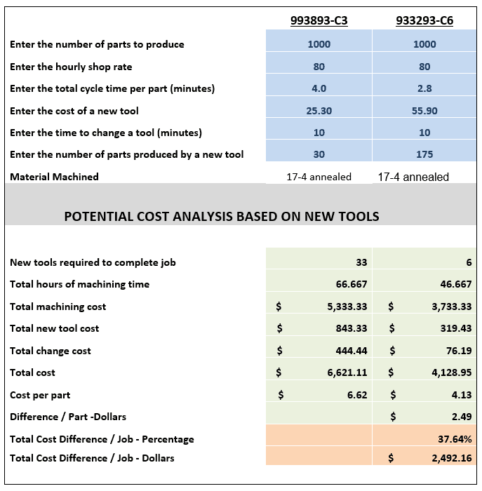
The following chart displays a cost analysis breakdown between a tool found in the Miniature End Mill section, item 993893-C3; and a tool found in the Material Specific End Mill section, item 933293-C6. When compared for the machining of 1,000 parts, the overall savings is nearly $2,500.
Material Specific Tooling Summarized
In conclusion, Material Specific End Mills have many benefits, but are best utilized in certain situations. While the initial cost of these tools are higher, they can work to save your shop time and money in the long run by lasting longer and producing more parts over a given period of time.
https://www.harveyperformance.com/wp-content/uploads/2019/02/Feature-Image-Material-Specific-Tooling-IMG.jpg5251400Harvey Performance Companyhttp://www.harveyperformance.com/wp-content/uploads/2018/08/Logo_HarveyPerformanceCompany-4.pngHarvey Performance Company2019-02-01 08:43:172024-04-11 16:58:13How Material Specific Tooling Pays Off
Do you know the key differences between a Single Form Thread Mill and a Multi-Form version? Do you know which tooling option is best for your job? This blog post examines how several factors, including the tool’s form and max depth of thread, are important to ultimately making the appropriate Harvey Tool decision.
Thread Mill Product Offering
Single Form
The single form thread mill is the most versatile threading solution Harvey Tool offers. These tools are ground to a sharp point and are capable of milling 60° thread styles, such as UN, metric, and NPT threads. With over 14 UN and 10 Metric sized tools, Harvey Tool’s single form selections allow machinists the opportunity to machine many different types of threads.
Harvey Performance Company, LLC.
Single Form Thread Mills for Hardened Steels
Similar to the standard single form, Harvey Tool’s thread mills for hardened steels offer machinists a quality option when dealing with hardened steels from 46-68 Rc. The following unique geometries helps this tool machine tough alloys:
Ground Flat – Instead of a sharp point these tools have a ground flat to help ensure long tool life.
Eccentric Relief – Gives the cutting edges extra strength for the high feeds at relatively low RPMs required for harder materials.
AlTiN Nano Coating – Allows for superior heat resistance.
Harvey Performance Company, LLC.
A key difference between the standard Single Form and the Single Form for Hardened Steels is that the tools for hardened steels are actually only capable of milling 83% of the actual thread depth. At first, this may seem detrimental to your operation. However, according to the Machinery’s Handbook 29th Edition, “Tests have shown that any increase in the percentage of full thread over 60% does not significantly increase the strength of the thread. Often, a 55% to 60% thread is satisfactory, although 75% threads are commonly used to provide an extra margin of safety.” With the ability to preserve tool life and effectively perform thread components, Harvey Tool’s single form thread mills for hardened steels are a natural choice when tackling a hardened material.
Tri-Form
Tri-Forms are designed for difficult-to-machine materials. The tri-form design reduces tool pressure and deflection, which results in more accurate threading. Its left-hand cut, left-hand spiral design allows it to climb mill from the top of the thread to the bottom.
Harvey Performance Company, LLC.
Multi-Form
Our multi-form thread mills are offered in styles such as UN, NPT, and Metric. Multi-Form tools are optimized to produce a full thread in single helical interpolation. Additionally, they allow a machinist to quickly turn around production-style jobs.
Harvey Performance Company, LLC.
Coolant-Through Multi Form Thread Mills
Coolant-Through Multi Form Thread Mills are the perfect tool for when a job calls for thread milling in a blind hole. The coolant through ability of the tool produces superior chip evacuation. These tools also improve coolant flow to the workpiece – delivering it directly from the tip of the tool – for decreased friction and high cutting speeds.
Harvey Performance Company, LLC.
Long Flute
These tools are great when a job calls for a deep thread, due to their long flute. Long Flutes also have a large cutter diameter and core, which provides the tool with improved tool strength and stability.
Harvey Performance Company, LLC.
N.P.T. Multi-Form
While it may seem obvious, N.P.T. Multi-Form Thread Mills are perfect for milling NPT threads. NPT threads are great for when a part requires a full seal, different from traditional threads that hold pieces together without the water-tight seal.
Harvey Performance Company, LLC.
https://www.harveyperformance.com/wp-content/uploads/2019/01/Feature-Image-Selecting-Thread-Mill-IMG.jpg5251400Ben Holmhttp://www.harveyperformance.com/wp-content/uploads/2018/08/Logo_HarveyPerformanceCompany-4.pngBen Holm2019-01-10 01:44:532024-04-30 09:42:20Confidently Select Your Next Thread Mill
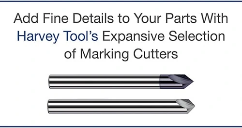
While similar on the surface, Half-round Engraving Cutters and Marking Cutters are actually very different. Both tools are unique in the geometries they possess, the benefits they offer, and the specific purposes they’re used for. Below are the key differences that all machinists must know, as the engraving on a part is often a critical step in the machining process.
Engravers & Marking Cutters Serve Different Purposes
All Marking Cutters are Engraving Cutters, but not all Engraving Cutters are Marking Cutters. This is because Marking Cutters are a “type” of engraving tool. By virtue of their sturdier geometry, these tools are suited for applications requiring repetition such as the engraving of serial numbers onto parts. Harvey Tool has been able to customize specific tool geometries for ferrous and non-ferrous applications, offering Marking Cutters for material specific purposes.
Engraving Cutters, on the other hand, are meant for finer detailed applications that require intricate designs such as engraving a wedding band or a complex brand design.
These Tools Have Unique Geometry Features
Historically, Engraving Cutters have been made as a half round style tool. This tool allows for a true point, which is better for fine detail, but can easily break if not run correctly. Because of this, these tools have performed well in softer materials such as aluminum and wood, especially for jobs that require an artistic engraving with fine detail.
Marking cutters are not as widely seen throughout the industry, however. These tools hold up in harder-to-machine materials exceedingly well. Marking Cutters are a form of Engraving Cutter that contain 2 flutes and a web at the tip, meaning that the tool has a stronger tip and is less susceptible to breakage.
While these tools do not contain a true point (due to their web), they do feature shear flutes for better cutting action and the ability to evacuate chips easier when compared to a half-round engraver.
Harvey Tool Product Offering
Harvey Tool offers a wide variety of both Engraving Cutters and Marking Cutters. Choose from a selection of pointed, double-ended, tip radius, and tipped-off Engraving Cutter styles in 15 included angles ranging from 10° to 120°.
Marking Cutters are fully stocked in tip radius or tipped-off options, and are designed specifically for either ferrous or non-ferrous materials. They are are offered in included angles from 20° to 120°.
While Engraving Cutters are offered uncoated or in AlTiN, AlTiN Nano, or Amorphous Diamond coatings, Marking Cutters are fully stocked in uncoated, AlTiN, or TiB2 coated styles.
While both Engraving Cutters and Marking Cutters can accomplish similar tasks, each tool has its own advantages and purpose. Selecting the correct tool is based largely on preference and applicability to the job at hand. Factors that could impact your selection would be final Depth of Cut, Width of Cut, the angle needing to be achieved, and the desired detail of the engraving.
Few steps in the machining process are as important as proper end mill selection. Complicating the process is the fact that each individual tool has its own unique geometries, each pivotal to the eventual outcome of your part. We recommend asking yourself 5 key questions before beginning the tool selection process. In doing so, you can ensure that you are doing your due diligence in selecting the best tool for your application. Taking the extra time to ensure that you’re selecting the optimal tool will reduce cycle time, increase tool life, and produce a higher quality product.
Question 1: What Material Am I Cutting?
Knowing the material you are working with and its properties will help narrow down your end mill selection considerably. Each material has a distinct set of mechanical properties that give it unique characteristics when machining. For instance, plastic materials require a different machining strategy – and different tooling geometries – than steels do. Choosing a tool with geometries tailored towards those unique characteristics will help to improve tool performance and longevity.
Helical Solutions also provides a diverse product offering tailored to specific materials, including Aluminum Alloys & Non-Ferrous Materials; and Steels, High-Temp Alloys, & Titanium. Each section includes a wide variety of flute counts – from 2 flute end mills to Multi-Flute Finishers, and with many different profiles, coating options, and geometries.
Question 2: Which Operations Will I Be Performing?
An application can require one or many operations. Common machining operations include:
Traditional Roughing
Slotting
Finishing
Contouring
Plunging
High Efficiency Milling
By understanding the operations(s) needed for a job, a machinist will have a better understanding of the tooling that will be needed. For instance, if the job includes traditional roughing and slotting, selecting a Helical Solutions Chipbreaker Rougher to hog out a greater deal of material would be a better choice than a Finisher with many flutes.
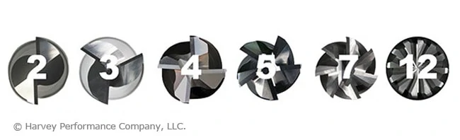
Question 3: How Many Flutes Do I Need?
One of the most significant considerations during end mill selection is determining proper flute count. Both the material and application play an important role in this decision.
Material:
When working in Non-Ferrous Materials, the most common options are the 2 or 3-flute tools. Traditionally, the 2-flute option has been the desired choice because it allows for excellent chip clearance. However, the 3-flute option has proven success in finishing and High Efficiency Milling applications, because the higher flute count will have more contact points with the material.
Ferrous Materials can be machined using anywhere from 3 to 14-flutes, depending on the operation being performed.
Application:
Traditional Roughing: When roughing, a large amount of material must pass through the tool’s flute valleys en route to being evacuated. Because of this, a low number of flutes – and larger flute valleys – are recommend. Tools with 3, 4, or 5 flutes are commonly used for traditional roughing.
Slotting: A 4-flute option is the best choice, as the lower flute count results in larger flute valleys and more efficient chip evacuation.
Finishing: When finishing in a ferrous material, a high flute count is recommended for best results. Finishing End Mills include anywhere from 5-to-14 flutes. The proper tool depends on how much material remains to be removed from a part.
High Efficiency Milling: HEM is a style of roughing that can be very effective and result in significant time savings for machine shops. When machining an HEM toolpath, opt for 5 to 7-flutes.
Question 4: What Specific Tool Dimensions are Needed?
After specifying the material you are working in, the operation(s) that are going to be performed, and the number of flutes required, the next step is making sure that your end mill selection has the correct dimensions for the job. Examples of key considerations include cutter diameter, length of cut, reach, and profile.
Cutter Diameter
The cutter diameter is the dimension that will define the width of a slot, formed by the cutting edges of the tool as it rotates. Selecting a cutter diameter that is the wrong size – either too large or small – can lead to the job not being completed successfully or a final part not being to specifications. For example, smaller cutter diameters offer more clearance within tight pockets, while larger tools provide increased rigidity in high volume jobs.
Length of Cut & Reach
The length of cut needed for any end mill should be dictated by the longest contact length during an operation. This should be only as long as needed, and no longer. Selecting the shortest tool possible will result in minimized overhang, a more rigid setup, and reduced chatter. As a rule of thumb, if an application calls for cutting at a depth greater than 5x the tool diameter, it may be optimal to explore necked reach options as a substitute to a long length of cut.
Tool Profile
The most common profile styles for end mills are square, corner radius, and ball. The square profile on an end mill has flutes with sharp corners that are squared off at 90°. A corner radius profile replaces the fragile sharp corner with a radius, adding strength and helping to prevent chipping while prolonging tool life. Finally, a ball profile features flutes with no flat bottom, and is rounded off at the end creating a “ball nose” at the tip of the tool. This is the strongest end mill style. A fully rounded cutting edge has no corner, removing the mostly likely failure point from the tool, contrary to a sharp edge on a square profile end mill. An end mill profile is often chosen by part requirements, such as square corners within a pocket, requiring a square end mill. When possible, opt for a tool with the largest corner radius allowable by your part requirements. We recommend a corner radii whenever your application allows for it. If square corners are absolutely required, consider roughing with a corner radius tool and finishing with the square profile tool.
Question 5: Should I Use a Coated Tool?
When used in the correct application, a coated tool will help to boost performance by providing the following benefits:
More Aggressive Running Parameters
Prolonged Tool life
Improved Chip Evacuation
Harvey Tool and Helical Solutions offer many different coatings, each with their own set of benefits. Coatings for ferrous materials, such as AlTiN Nano or TPlus, typically have a high max working temperature, making them suitable for materials with a low thermal conductivity. Coatings for non-ferrous applications, such as TiB2 or ZPlus, have a low coefficient of friction, allowing for easier machining operations. Other coatings, such as Amorphous Diamond or CVD Diamond Coatings, are best used in abrasive materials because of their high hardness rating.
Ready to Decide on an End Mill
There are many factors that should be considered while looking for the optimal tooling for the job, but asking the aforementioned five key question during the process will help you to make the right decision. As always, The Harvey Performance Company Technical Service Department is always available to provide recommendations and walk you through the tool selection process, if need be.
https://www.harveyperformance.com/wp-content/uploads/2018/10/Feature-Image-5-Questions-IMG-2.jpg5251400Harvey Performance Companyhttp://www.harveyperformance.com/wp-content/uploads/2018/08/Logo_HarveyPerformanceCompany-4.pngHarvey Performance Company2018-10-16 09:00:242023-10-24 10:42:255 Questions to Ask Before Selecting an End Mill
We use cookies to ensure that we give you the best experience on our website. If you continue to use this site we will assume that you are happy with it.Ok