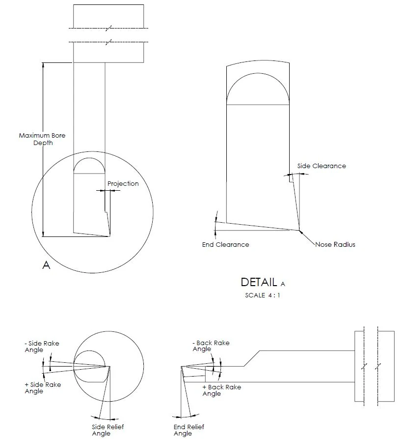
Understanding Key Qualities in Micro 100’s Offering of Micro-Quik Quick Change Tool Holders

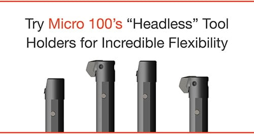
Did you know that, along with supplying the machining industry with premier turning tools, Micro 100 also fully stocks tool holders for its proprietary Micro-Quik Quick Change Tool Holder System? In fact, Micro 100’s Spring 2021 Product Catalog introduced new “headless” style tool holders, which are revolutionizing the machine setup process for turning operations.

This “In the Loupe” guide is designed to provide you with insight for navigating Micro 100’s offering, and to help you select the optimal holder style for your operation.

Micro 100 ad showing four different tool holders

Understanding Micro 100’s Micro-Quik

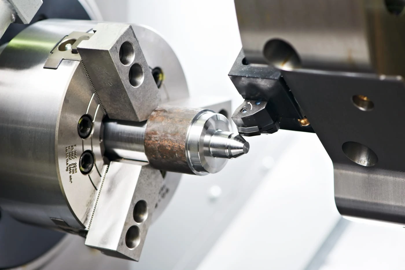
Micro 100’s Micro-Quik is unlike any other tool change system you may have seen from other tool manufacturers because of its incredible axial and radial repeatability and its ease of use. This foolproof system delivers impressive repeatability, tip-to-tip consistency, and part-to-part accuracy, all the while resulting in tool changes that are 90 % faster than conventional methods.

In all, a tool change that would regularly take more than 5 minutes is accomplished in fewer than 30 seconds.

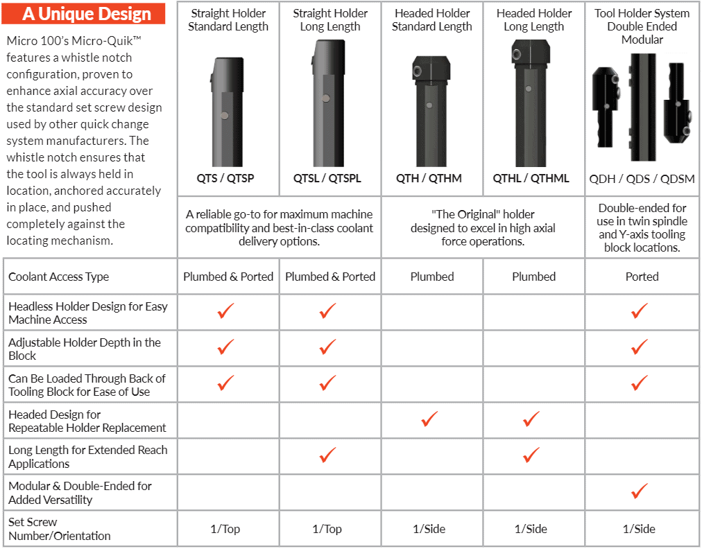
Micro 100 Quick Change Tool Holder Selection

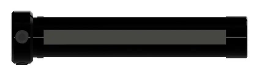
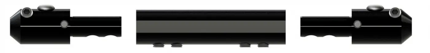
Straight Style, Headless Tool Holders

When using a straight style tool holder, you will enjoy significantly enhanced versatility during the machine set up process. These holders are engineered specifically for use in any Swiss, standard lathe, or multi-function lathe, and allow for adjustable holder depth in a tooling block. Radial coolant access ports provide easier access to coolant and the ability to utilize coolant through functionality in tooling blocks that share a static and live tool function, and cannot be plumbed through the back of the holder. Further, their headless design allows for installation through the backside of the tooling block in machines where the work envelope is limited, allowing for a simplified installation process.

Created by Harvey Performance Company Application Engineers, the following videos outline the simple process for inserting each style of Micro 100 Straight Tool Holder into a tooling block.

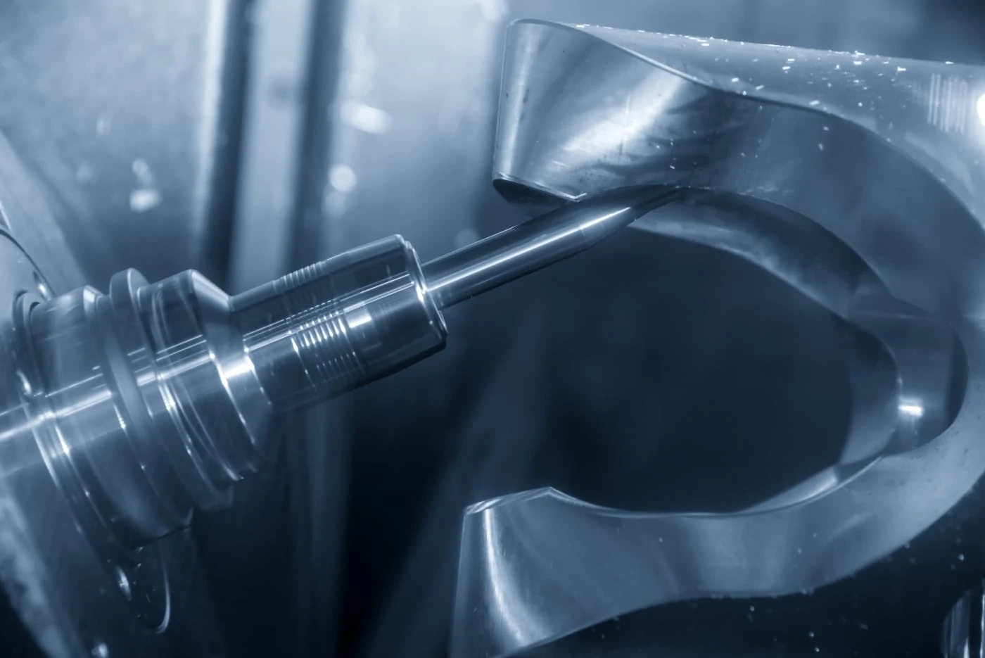
Micro 100 Straight Holder, Plumbed Style (QTS / QTSL)

In the video, you’ll notice that the first step is to place your Micro-Quik tool in this quick change holder, and align it with the locating pin. Then, tighten the locating and locking screw into the whistle notch. This forces the tool against the locking pin, and allows for repeatable accuracy, every time. From there, the quick change tool holder can be installed as a unit into a tooling block. When desired tool position is achieved, set screws can be tightened to lock the holder in place.

Micro 100 Straight Holder, Plumbed & Ported Style (QTSP / QTSPL)

This unique Micro 100 quick change tool holder style is plumbed and ported, allowing for enhanced versatility and coolant delivery efficiency. The setup process using this style of holder is also simple. First, place your Micro 100 quick change tool into the holder, and align it with the locating pin. From there, tighten the locating and locking screw into the whistle notch, forcing the tool against the locating pin and allowing for repeatable accuracy, every time. When plumbed coolant is being used, remove the plumbed plug in the back of the holder, and connect the appropriate coolant adapter and line. Then, the holder can be installed as a unit into the tooling block and locked into place with set screws.

When using ported coolant, make sure that the coolant plug in the back of the holder is tightly installed. Then, be sure to only use one of the radial ports. Simply plug the two that aren’t in use. Install the provided porting adapter to allow for coolant access. Porting options allow for coolant capabilities in machine areas where coolant is not easily accessible.

Headed Tool Holders

headed quick change tool holder

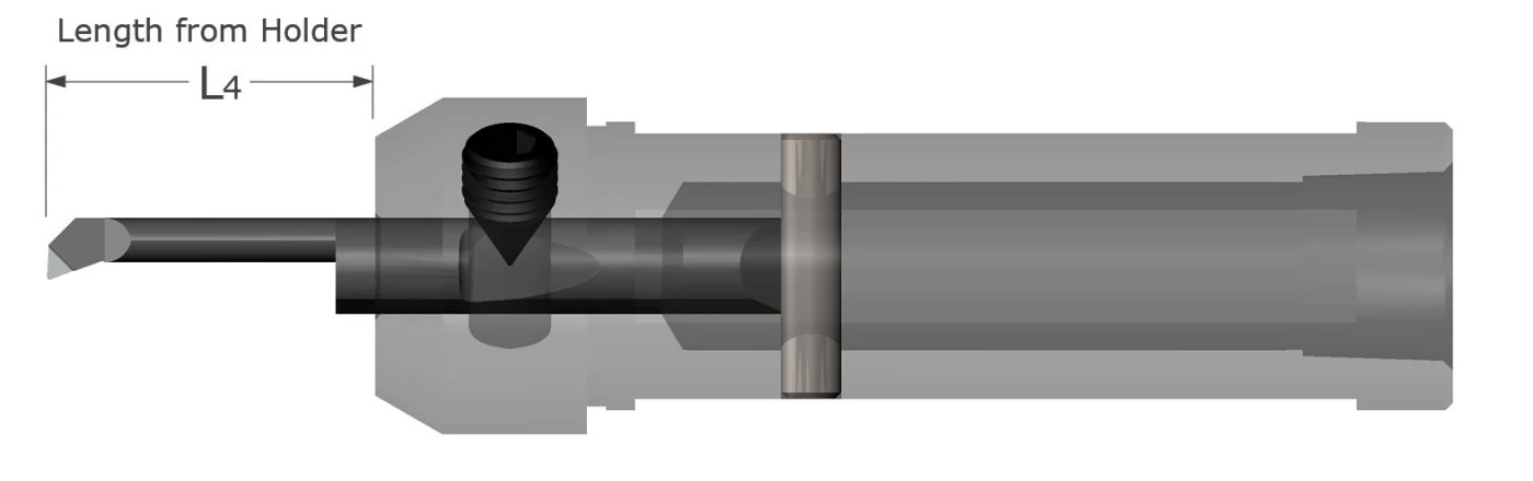
Micro 100’s original quick change tool holder for its Micro-Quik system, this style of tool holder for lathe applications features a unique “3 point” locking and locating system to ensure repeatability. When conducting a tool change with this tool holder style, you must follow a simple, 3-step process:

  1. Loosen the tool holder’s set screw
  2. Remove the used tool from the holder
  3. Insert the new tool and retighten the set screw

These headed holders are plumbed through the back of the holder for NPT coolant connection and are available in standard length and long length styles.

Try Micro 100’s “Headless” Tool Holders for Incredible Flexibility

Double-Ended Modular Tool Holder System

double ended quick change tool holder

For twin spindle and Y-axis tooling block locations, Micro 100 fully stocks a double-ended modular system. Similar to its single-ended counterparts, this modular is headless, meaning it enhances machine access during the tool block installation process, and the holder depth can be adjusted while in the block. Because this system is double-ended, however, there is obviously no plumbed coolant option through the end of the tool. Instead, coolant is delivered via an external coolant port, the adapter for which is included in the purchase of the modular system. Right hand and left hand tool holders are designed so the set screws are facing the operator for easy access. Both right and left hand styles are designed for right hand turning.

Enjoy Quick Change Tool Holding Confidence & Ease of Use

When opting for a quick change system, machinists long for simplicity, versatility, and consistency. Though many manufacturers have a system of their own, Micro 100’s Micro-Quik sets itself apart with axial and radial repeatability, and tip-to-tip consistency. Further, Micro 100 fully stocks several quick change tool holder options, allowing a machinist to select the style that best fits their application.

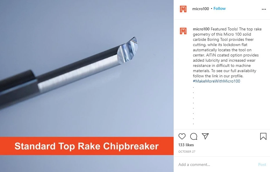
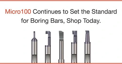
Micro100 also manufactures and stocks a wide variety of boring tools for the Micro-Quik. Click here to learn more.

For more information on selecting the appropriate quick change tool holder for your job, view our selection chart or call an experienced Micro 100 technical engineer at 800-421-8065.

quick change tool holder selection chart for Micro100

8 Unique Facts About Thread Forming Taps

Unlike most CNC cutting tools, Thread Forming Taps, otherwise known as Form Taps, Forming Taps, or Roll Taps, work by molding the workpiece rather than cutting it. Because of this, Form Taps do not contain any flutes, as there is no cutting action taking place, nor are there any chips to evacuate. Below are 8 unique facts of Thread Forming Taps (and some may surprise you).

1. Chips Aren’t Formed

When using a Form Tap, chips are not formed, nor is any part material evacuated (Yes, you read that right). With thread forming, the tool is void of any flutes, as chip evacuation is not a concern. Form Taps quite literally mold the workpiece, rather than cut it, to produce threads. Material is displaced within a hole to make way for the threads being formed.

Increase Your Tapping Efficiency 20x With Titan USA’s Thread Form Taps

2. Cutting Oils Allow for Reduced Friction & Heat Generation

Did you know that Thread Forming Taps require good lubrication? But why is that the case if chips are not being evacuated, and how does lubrication enter the part with such a limited area between the tool and the perimeter of the hole being threaded? Despite the fact that chips aren’t being formed or evacuated, cutting oils aid the Form Tap as it interacts with the part material, and reduces friction and heat generation. Lube vent grooves are narrow channels engineered into the side of Forming Taps that are designed to provide just enough room for lubricant to make its way into – and out of – a part.

titan usa thread forming tool

Not all materials are well suited for Thread Forming Taps. In fact, attempting to use a tap in the wrong material can result in significant part and tool damage. The best materials for this unique type of operation include aluminum, brass, copper, 300 stainless steel, and leaded steel. In other words, any material that leaves a stringy chip is a good candidate for cold forming threads. Materials that leave a powdery chip, such as cast iron, are likely too brittle, resulting in ineffective, porous threads.

4. Threads Produced Are Stronger Than Conventional Tapping Threads

Thread forming produces much stronger threads than conventional tapping methods, due to the displacements of the grain of the metal in the workpiece. Further, cutting taps produce chips, which may interfere with the tapping process.

5. Chip Evacuation is Never a Concern With Thread Forming

In conventional tapping applications, as with most machining applications, chip evacuation is a concern. This is especially true in blind holes, or holes with a bottom, as chips created at the very bottom of the hole oftentimes have a long distance to travel before being efficiently evacuated. With form taps, however, chip removal is never a concern.

6. Form Taps Offer Extended Tool Life

Thread Forming Taps are incredibly efficient, as their tool life is substantial (Up to 20x longer than cutting taps), as they have no cutting edges to dull. Further, Thread Forms can be run at faster speeds (Up to 2x faster than Cutting Taps).

Pro Tip: To prolong tool life even further, opt for a coated tool. Titan USA Form Taps, for example, are fully stocked in both uncoated and TiN coated styles.

titan usa thread forming tool on stack of red product packaging containers

7. A Simple Formula Will Help You Find the Right Drill Size

When selecting a Tap, you must be familiar with the following formula, which will help a machinist determine the proper drill size needed for creating the starter hole, before a Thread Forming Tap is used to finish the application:

Drill Size = Major Diameter – [(0.0068 x desired % of thread) / Threads Per Inch]
Drill Size (mm) = Major Diameter – [(0.0068 x desired % of thread x pitch (mm)]

two titan usa thread form taps

8. Thread Forming Taps Need a Larger Hole Size

  1. Thread Form Taps require a larger pre-tap hole size than a cutting tap. This is because these tools impact the sides of the hole consistently during the thread forming process. If the pre-tap hole size is too small, the tool would have to work too hard to perform its job, resulting in excessive tool wear, torque, and possible breakage.

As an example, a ¼-20 cut tap requires a #7 drill size for the starter hole, whereas a ¼-20 roll tap requires a #1 drill size for 65% thread.

CNC Machining & 3D Printing: A Hybrid Approach to Precision Manufacturing

With recent advancements in 3D printing capabilities, it is becoming easier for manufacturers to use additive manufacturing to create parts from a wide variety of materials, including polymers like ABS, TPE, and PLA as well as carbon fiber composites, nylon, and polycarbonates. Even pricey metals like Titanium, Stainless Steel, and Inconel are becoming increasingly common in the world of additive manufacturing as well.

There is no doubt that the additive manufacturing space will continue to develop and grow in the coming years, but will it render subtractive manufacturing methods like CNC Machining obsolete? Absolutely not. In fact, precision CNC machining is likely more important to the additive manufacturing process than you may think, as a new process called “hybrid manufacturing” is quickly taking hold in the industry.

3d printing metal
3D printing of metal parts is becoming more common, but subtractive manufacturing is an important part of manufacturing precision additive parts.

Additive Manufacturing vs. Subtractive Manufacturing

Before implementing a hybrid manufacturing approach, it is important to understand the pros and cons of each method. Here is a quick breakdown of both additive and subtractive manufacturing, and the benefits and drawbacks of each.

Additive ManufacturingSubtractive Manufacturing
Adds material layers to create partsRemoves material layers to create parts
Slower process, better for small production runsFaster process, better for large production runs
Better for smaller partsBetter for larger parts
Rough surface finish that requires significant post-operation finishingMore definied surface finish with minimal post-operation finishing required
Less precise part tolerancesAble to hold extremely precise part tolerances
Cheaper material costsMore expensive material costs
Less material wasteMore material waste
Intricate details easier to createIntricate details can require complex programs and additional capabilities (5 axis)

Using CNC Machining to Create Precise 3D Printed Parts

Looking at the chart above, you will notice that one of the key differences between additive manufacturing and subtractive manufacturing is the surface finish and tolerances that can be achieved with each method. This is where a hybrid approach to additive manufacturing can be extremely beneficial.

As parts come off the printer, they can be quickly moved into a CNC machine with a program designed for part completion. The CNC machine will be able to get 3D printed parts down to the tight tolerances required by many industries and reach the desired surface finish. Advanced finishing tools and long reach, tapered tools from brands like Harvey Tool can easily machine the tight geometries of 3D printed parts, while extremely sharp diamond-coated tooling and material-specific tools designed for plastics and composites can work to create a beautiful, in-tolerance finished part regardless of the material.

long reach end mill
Long reach tools can easily machine hard to reach, intricate part details on 3D printed parts.

By designing a workflow like this in your shop, you can spend less time worrying about the precision of printed parts by adding in subtractive operations to keep material costs low, create less waste, and keep parts in tight tolerances for precision machining excellence.

Using 3D Printing to Increase CNC Machining Efficiency

If your shop is focused completely on subtractive manufacturing methods, you are probably thinking that there is no need for an additive option in your shop. Can’t a CNC machine create everything a 3D printer can, and in less time? Not necessarily. Again, by using the two methods together and taking a hybrid approach, you may be able to lower your manufacturing and material costs.

For example, you could machine the bulk of a part with typical subtractive machines, which would likely take a very long time using additive methods. Then you can go back to that part with a 3D printer to add intricate features to the part that may take complex programming and hours of planning on a subtractive machine. An impeller is a great example, where the bulk of that part can be machined, but the tricky fins and blades could be printed onto the part, and then finished back on the CNC machine.

3d printed metal parts
3D printed impeller waiting for finishing operations

The ability of additive machines to literally “add-on” to a part can also make for a cheaper approach to part design. Instead of using expensive materials like Inconel or Titanium to machine an entire part, portions of the part that do not require extreme heat resistance could be machined out of cheaper steel, while the heat resistant portions using expensive materials can be added later through additive methods.

Hybrid Manufacturing Machines

As hybrid manufacturing workflows become more popular, so do new hybrid manufacturing machines. These hybrid machines are all-in-one machines where both additive and subtractive manufacturing can be performed in a single setup. Many of these machines offer metal 3D printing as well as multi-axis machining capabilities, ready for even the most complex parts thrown their way. With a bit of customization, large-scale 3D printing machines or CNC mills can be retrofit to allow for hybrid manufacturing with add-ons from companies like Hybrid Manufacuring Technologies.

hybrid manufacturing machines
Example of a hybrid machine add-on from Hybrid Manufacturing Technologies, featuring 3D printing spindles and milling tools in the same machine carousel.

As manufacturing and design techniques get progressively “smarter” with CAM/CAD programs offering generative design and artificial intelligence, these hybrid machines could become a new standard in high-end machine shops working in advanced manufacturing industries like aerospace, medical, defense, and the mold, tool & die market.

Overall, in 2021 we are still early on in this new revolution of hybrid machining and advanced design methods, but it is important to understand the role that adding a CNC machine could have in your additive-focused shop, and vice versa. By combining additive and subtractive together, shops can mitigate the cons of each method and take full advantage of the benefits of having both options available on the shop floor.

Causes & Effects of Built-Up Edge (BUE) in Turning Applications

In turning operations, the tool is stationary while the workpiece is rotating in a clamped chuck or a collet holder. Many operations are performed in a lathe, such as facing, drilling, grooving, threading, and cut-off applications. it is imperative to use the proper tool geometry and cutting parameters for the material type that is being machined. If these parameters are not applied correctly in your turning operations, built-up edge (BUE), or many other failure modes, may occur. These failure modes adversely affect the performance of the cutting tool and may lead to an overall scrapped part.

downloadable speeds and feeds charts ad

Common Types of Tool Failure


When inspecting a cutting tool under a microscope or eye loupe, there are several different types of turning tool failure modes that can be apparent. Some of the most common modes are:

  • Normal Flank Wear: The only acceptable form of tool wear, caused by the normal aging of a used cutting tool and found on the cutting edges.
    • This abrasive wear, caused by hard constituents in the workpiece material, is the only preferred method of tool wear, as it’s predictable and will continue to provide stable tool life, allowing for further optimization and increased productivity.
  • Cratering: Deformations found on the cutting face of a tool.
    • This tool mode is a chemical and heat failure, localized on the rake face area of the turning tool, or insert. This failure results from the chemical reaction between the workpiece material and the cutting tool and is amplified by cutting speed. Excessive Crater Wear weakens a turning tool’s cutting edge and may lead to cutting edge failure.
  • Chipping: Breaking of the turning tool along its cutting face, resulting in an inaccurate, rough cutting edge.
    • This is a mechanical failure, common in interrupted cutting or non-rigid machining setups. Many culprits can be to blame for chipping, including machine mishaps and tool holder security.
  • Thermal Mechanical Failure (Thermal Cracking): The thermal cracking of a cutting tool is due to significant swings in machining temperature.
    • When turning, heat management is key. Too little or too much heat can create issues, as can significant, fast swings in temperature (repeated heating and cooling on the cutting edge). Thermal Mechanical Failure usually shows in the form of evenly spaced cracks, perpendicular to the cutting edge of the turning tool.
  • Built-Up Edge (BUE): When chips adhere to the cutting tool due to high heat, pressure, and friction.

Effects of Built-Up Edge in Turning Application

What Is BUE In Machining?

A built-up edge is perhaps the easiest mode of tool wear to identify, as it may be visible without the need for a microscope or an eye loupe. The term built-up edge means that the material that you’re machining is being pressure welded to the cutting tool. When inspecting your tool, evidence of a BUE problem is material on the rake face or flank face of the cutting tool.

built up cutting edge on turning tools
Image Source: Carbide inserts Wear Failure modes. | machining4.eu, 2020

Problems With BUE

This condition can create a lot of problems with your machining operations, such as poor tool life, subpar surface finish, size variations, and many other quality issues. The reason for these issues is that the centerline distance and the tool geometry of the cutting edge are being altered by the material that’s been welded to the rake or flank face of the tool. As the BUE condition worsens, you may experience other types of failures or even catastrophic failure.                     

Causes of Built-Up Edge in Turning Applications

Improper Tooling Choice

Built-Up Edge is oftentimes caused by using a turning tool that does not have the correct geometry for the material being machined. Most notably, when machining a gummy material such as aluminum or titanium, your best bet is to use tooling with extremely sharp cutting edges, free cutting geometry, and a polished flank and rake face. This will not only help you to cut the material swiftly but also to keep it from sticking to the cutting tool.

four different gold edge turning tools

Using Aged Tooling

Even when using a turning tool with correct geometry, you may still experience BUE. As the tool starts to wear and its edge starts to degrade, the material will start building up on the surface of the tool. For this reason, it is very important to inspect the cutting edge of a tool after you have machined a few parts, and then randomly throughout the set tool life. This will help you identify the root cause of any of the failure modes by identifying them early on.

Eliminate BUE With Micro 100 Speeds and Feeds Charts

Insufficient Heat Generation

Built-up edge can be caused from running a tool at incorrect cutting parameters. Usually, when BUE is an issue, it’s due to the speed or feed rates being too low. Heat generation is key during any machining application – while too much heat can impact a part material, too little can cause the tool to be less effective at efficiently removing chips.

4 Simple Ways to Mitigate Built-Up Edge in Turning Applications

Chipbreaker Tooling

When selecting a tool, opt for free cutting, up sharp geometries with highly polished surfaces. Selecting a tool with chipbreaker geometry will also help to divide chips, which will help to remove it from the part and the cutting surface. Boring bars with chipbreaker geometry allow for maximum control over the chips leading to freer cutting when turning.

Correct Speeds and Feeds

Be confident in your application approach and your running parameters. It’s always important to double-check that your speeds and feeds are appropriate for your turning application. Ensure the condition of your machine is optimal as older machines used for abrasive materials may display backlash. Consult your tooling manufacturer for recommended speeds and feeds and to prevent from aggressively running your machine more than it can handle.

metal blank machining process on lathe with cutting tool

Coolant Usage

When coolant is directed towards a part, it can evacuate chips and aid in preventing high temperatures from melting onto the cutting edge. Thus, BUE is less likely to occur when coolant is utilized. Make sure the coolant is focused on the cutting edge and increase the coolant concentration amount.

Tool Coatings

Opt for a coated insert, as tool coatings are specifically engineered for a given set of part materials, and are designed to prevent common machining woes. Coatings are designed to minimize the impact of cutting forces and to keep tool failure at bay. Machinists must select the right material specific coating for their turning operations in order to promote the life of their tools.

micro 100 solid carbide turning tool Instagram post

Save Time With Quick Change Tooling

Making a manual tool change on any CNC machine is never a timely or rewarding process. Typically, a tool change in a standard holder can take up to 5 minutes. Add that up a few times, and suddenly you have added significant minutes to your production time.

As CNC machine tool and cutting tool technology has advanced, there are more multi-functional tools available to help you avoid tool changes. However, sometimes it just isn’t feasible, and multiple tool changes are needed. Luckily, Micro 100 has developed a revolutionary new method to speed up tool changes significantly.

What is the Micro-Quik Tooling System?

Developed in Micro 100’s world-class grinding facility in Meridian, Idaho, the Micro 100 Micro-Quik tooling system is held to the same standards and tight tolerances as all of the Micro 100 carbide tooling.

The quick change tooling system allows for highly repeatable tool changes that save countless hours without sacrificing performance. This system combines a unique tool holder with a unique tool design to deliver highly repeatable and accurate results.

Each quick change tool holder features a locating/locking set screw to secure the tool and a locating pin which helps align the tool for repeatability. Removing a tool is as simple as loosening the set screw and inserting its replacement.

depiction of removing tool from quick change system

During tool changes, the precision ground bevel on the rear of the tool aligns with a locating pin inside the tool holder. The distance from this locational point to the tip of the tool is highly controlled under tight tolerances, meaning that the Micro-Quik tooling system ensures a very high degree of tool length and centerline repeatability. The “L4” dimension on all of our quick change tools, as seen in the image above, remains consistent across the entire product line. Check out the video below for a demonstration of the Micro 100 Micro-Quik system in action!

Quick Change Tooling Benefits

quick change system with micro 100 boring bar close up image

The most obvious benefit to using Micro 100’s Micro-Quik Quick Change Tooling System is the time savings that come with easier tool changes. By using the quick change holders in combination with quick change tooling, it is easy to reduce tool changes from 5 minutes to under 30 seconds, resulting in a 90% decrease in time spent swapping out tools. This is a significant benefit to the system, but there are benefits once the tool is in the machine as well.

As mentioned above, the distance from the locational point on each tool shank to the tip of the tool is highly controlled, meaning that regardless of which type of tool you insert into the holder, your stick out will remain the same. This allows you to have confidence in the tooling and does not require additional touch offs, which is another major time saver.

assortment of boring bars with quick change system

By removing additional touch-offs and tool changes from your workflow, you also reduce the chances for human or machine error. Improper touch-offs or tool change errors can cause costly machine crashes and result in serious repairs and downtime. With the Micro 100 Micro-Quik Quick Change Tooling System, initial setups become much easier, allowing you to hit the cycle start button with total confidence for each run.

By making a few simple changes to your tool holding configurations and adopting the Micro-Quik system, your shop can save thousands in time saved, with less machine downtime and increased part production. To learn more about the Micro 100 Micro-Quik cutting tools and tool holders, please visit Micro 100.

5 Things to Know About Helical’s High Feed End Mills

Helical Solutions‘ High Feed End Mills provide many opportunities for machinists, and feature a special end profile to increase machining efficiencies. A High Feed End Mill is a High Efficiency Milling (HEM) style tool with specialized end geometry that utilizes chip thinning, allowing for drastically increased feed rates in certain applications. While standard end mills have square, corner radius, or ball profiles, this Helical tool has a specialized, very specific design that takes advantage of chip thinning, resulting in a tool that can be pushed harder than a traditional end mill.

helical solutions high feed end mills ad with both solid round and coolant through options

Below are 5 things that all machinists should know about this exciting Helical Solutions product offering.

1. They excel in applications with light axial depths of cut

A High Feed End Mill is designed to take a large radial depth of cut (65% to 100% of the cutter diameter) with a small axial depth of cut (2.5% to 5% diameter) depending on the application. This makes them perfect for face milling, roughing, slotting, deep pocketing, and 3D milling. Where HEM toolpaths involve light radial depths of cut and heavy axial depths of cut, these utilize high radial depths of cut and smaller axial depths of cut.

2. This tool reduces radial cutting forces

The end profile of this tool is designed to direct cutting forces upward along the axis of the tool and into the spindle. This reduces radial cutting forces which cause deflection, allowing for longer reach tools while reducing chatter and other issues that may otherwise lead to tool failure. The reduction of radial cutting forces makes this tool excellent for use in machines with lower horsepower, and in thin wall machining applications.

3. High Feed End Mills are rigid tools

The design and short length of cut of these end mills work in tandem with the end geometry to produce a tool with a strong core, further limiting deflection and allowing for tools with greater reach lengths.

Push Harder in HEM With Helical Solutions’ High Feed End Mills

4. They can reduce cycle times

In high RDOC, low ADOC applications, these tools can be pushed significantly faster than traditional end mills, saving time and money over the life of the tool.

5. High Feed End Mills are well suited for hard materials

The rigidity and strength of High Feed End Mills make them excellent in challenging to machine materials. Helical’s High Feed End Mills come coated with Tplus coating, which offers high hardness and extended tool life in high temp alloys and ferrous materials up to 45Rc.

In summary, these tools with specialized end geometry that utilizes chip thinning and light axial depths of cut to allow for significantly increased feed rates in face milling, slotting, roughing, deep pocket milling, and 3D milling applications. The end profile of a High Feed End Mill applies cutting forces back up into the spindle, reducing radial forces that lead to deflection in long reach applications. Combining this end geometry with a stubby length of cut results in a tool that is incredibly rigid and well suited for harder, difficult to machine materials.

Benefits & Drawbacks of High and Low Helix Angles

While many factors impact the outcome of a machining operation, one often overlooked factor is the cutting tool’s helix angle. The Helix angle of a tool is measured by the angle formed between the centerline of the tool and a straight line tangent along the cutting edge.

A higher helix angle, usually 40° or more, will wrap around the tool “faster,” while a “slower” helix angle is usually less than 40°.

When choosing a tool for a machining operation, machinists often consider the material, the tooling dimensions and the flute count. The helix angle must also be considered to contribute to efficient chip evacuation, better part finish, prolonged tool life, and reduced cycle times.

Helix Angles Rule of Thumb

One general rule of thumb is that as the helix angle increases, the length of engagement along the cutting edge will decrease. That said,
there are many benefits and drawbacks to slow and high helix angles that can impact any machining operation.

Slow Helix Tool <40°

Benefits

  • Enhanced Strength – A larger core creates a strong tool that can resist deflection, or the force that will bend a tool under pressure.
  • Reduced Lifting – A slow helix will decrease a part from lifting off of the worktable in settings that are less secure.
  • Larger Chip Evacuation – The slow helix allows the tool to create a large chip, great for hogging out material.

Drawbacks

  • Rough Finish – A slow helix end mill takes a large chip, but can sometimes struggle to evacuate the chip. This inefficiency can result in a sub-par part finish.
  • Slower Feed Rate – The increased radial force of a slow helix end mill requires running the end mill at a slower feed rate.

High Helix Tool >40°

Benefits

  • Lower Radial Force – The tool will run quieter and smoother due to better shearing action, and allow for less deflection and more stability in thin wall applications.
  • Efficient Chip Evacuation – As the helix angle increases, the length of cutting edge engagement will decrease, and the axial force will increase. This lifts chips out and away, resulting in efficient chip evacuation.
  • Improved Part Finish – With lower radial forces, high helix tools are able to cut through material much more easily with a better shearing action, leaving an improved surface finish.

Drawbacks

  • Weaker Cutting Teeth – With a higher helix, the teeth of a tool will be thinner, and therefore thinner.
  • Deflection Risk – The smaller teeth of the high helix tool will increase the risk of deflection, or the force that will bend a tool under pressure. This limits how fast you can push high helix tools.
  • Increased Risk of Tool Failure – If deflection isn’t properly managed, this can result in a poor finish quality and tool failure.

Helix Angle: An Important Decision

In summary, a machinist must consider many factors when choosing tools for each application. Among the material, the finish requirements, and acceptable run times, a machinist must also consider the helix angle of each tool being used. A slow helix end mill will allow for larger chip formation, increased tool strength and reduce lifting forces. However, it may not leave an excellent finish. A high helix end mill will allow for efficient chip evacuation and excellent part finish, but may be subject to increased deflection, which can lead to tool breakage if not properly managed.

Selecting the Right Chamfer Cutter Tip Geometry

A chamfer cutter, or a chamfer mill, can be found at any machine shop, assembly floor, or hobbyist’s garage. These cutters are simple tools that are used for chamfering or beveling any part in a wide variety of materials. There are many reasons to chamfer a part, ranging from fluid flow and safety, to part aesthetics.

Due to the diversity of needs, tooling manufacturers offer many different angles and sizes of chamfer cutters, and as well as different types of chamfer cutter tip geometries. Harvey Tool, for instance, offers 21 different angles per side, ranging from 15° to 80°, flute counts of 2 to 6, and shank diameters starting at 1/8” up to 1 inch.

After finding a tool with the exact angle they’re looking for, a customer may have to choose a certain chamfer cutter tip that would best suit their operation. Common types of chamfer cutter tips include pointed, flat end, and end cutting. The following three types of chamfer cutter tip styles, offered by Harvey Tool, each serve a unique purpose.

Harvey Tool Chamfer Cutters

Pointed and Flat End Chamfer Cutters

Three Types of Harvey Tool Chamfer Cutters

Type I: Pointed

This style of chamfer cutter is the only Harvey Tool option that comes to a sharp point. The pointed tip allows the cutter to perform in smaller grooves, slots, and holes, relative to the other two types. This style also allows for easier programming and touch-offs, since the point can be easily located. It’s due to its tip that this version of the cutter has the longest length of cut (with the tool coming to a finished point), compared to the flat end of the other types of chamfer cutters. With only a 2 flute option, this is the most straightforward version of a chamfer cutter offered by Harvey Tool.

Type I Chamfer Cutter overview

Type II: Flat End, Non-End Cutting

Type II chamfer cutters are very similar to the type I style, but feature an end that’s ground down to a flat, non-cutting tip. This flat “tip” removes the pointed part of the chamfer, which is the weakest part of the tool. Due to this change in tool geometry, this tool is given an additional measurement for how much longer the tool would be if it came to a point. This measurement is known as “distance to theoretical sharp corner,” which helps with the programming of the tool. The advantage of the flat end of the cutter now allows for multiple flutes to exist on the tapered profile of the chamfer cutter. With more flutes, this chamfer has improved tool life and finish. The flat, non-end cutting tip flat does limit its use in narrow slots, but another advantage is a lower profile angle with better angular velocity at the tip.

Type II Chamfer Cutter overview

Type III: Flat End, End Cutting

Type III chamfer cutters are an improved and more advanced version of the type II style. The type III boasts a flat end tip with 2 flutes meeting at the center, creating a center cutting-capable version of the type II cutter. The center cutting geometry of this cutter makes it possible to cut with its flat tip. This cutting allows the chamfer cutter to lightly cut into the top of a part to the bottom of it, rather than leave material behind when cutting a chamfer. There are many situations where blending of a tapered wall and floor is needed, and this is where these chamfer cutters shine. The tip diameter is also held to a tight tolerance, which significantly helps with programing it.

Type III Chamfer Cutter overview

In conclusion, there could be many suitable cutters for a single job, and there are many questions you must ask prior to picking your ideal tool. Choosing the right angle comes down to making sure that the angle on the chamfer cutter matches the angle on the part. One needs to be cautious of how the angles are called out, as well. Is the angle an “included angle” or “angle per side?” Is the angle called off of the vertical or horizontal? Next, the larger the shank diameter, the stronger the chamfer and the longer the length of cut, but now, interference with walls or fixtures need to be considered. Flute count comes down to material and finish. Softer materials tend to want less flutes for better chip evacuation, while more flutes will help with finish. After addressing each of these considerations, the correct style of chamfer for your job should be abundantly clear.

How Boring Bar Geometries Impact Cutting Operations

Boring is a turning operation that allows a machinist to make a pre-existing hole bigger through multiple iterations of internal boring. It has a number of advantages over traditional hole finishing methods:

  • The ability to cost-effectively produce a hole outside standard drill sizes
  • The creation of more precise holes, and therefore tighter tolerances
  • A greater finish quality
  • The opportunity to create multiple dimensions within the bore itself
boring bar dimension explanation

Solid carbide boring bars, such as those offered by Micro 100,  have a few standard dimensions that give the tool basic functionality in removing material from an internal bore. These include:

Minimum Bore Diameter (D1): The minimum diameter of a hole for the cutting end of the tool to completely fit inside without making contact at opposing sides

Maximum Bore Depth (L2): Maximum depth that the tool can reach inside a hole without contact from the shank portion

Shank Diameter (D2): Diameter of the portion of the tool in contact with the tool holder

Overall Length (L1): Total length of the tool

Centerline Offset (F): The distance between a tool’s tip and the shank’s centerline axis

Micro100 Continues to Set the Standard for Boring Bars, Shop Today.

Tool Selection

In order to minimize tool deflection and therefore risk of tool failure, it is important to choose a tool with a max bore depth that is only slightly larger than the length it is intended to cut. It is also beneficial to maximize the boring bar and shank diameter as this will increase the rigidity of the tool. This must be balanced with leaving enough room for chips to evacuate. This balance ultimately comes down to the material being bored. A harder material with a lower feed rate and depths of cut may not need as much space for chips to evacuate, but may require a larger and more rigid tool. Conversely, a softer material with more aggressive running parameters will need more room for chip evacuation, but may not require as rigid of a tool.

Geometries

In addition, they have a number of different geometric features in order to adequately handle the three types of forces acting upon the tool during this machining process. During a standard boring operation, the greatest of these forces is tangential, followed by feed (sometimes called axial), and finally radial. Tangential force acts perpendicular to the rake surface and pushes the tool away from the centerline. Feed force does not cause deflection, but pushes back on the tool and acts parallel to the centerline. Radial force pushes the tool towards the center of the bore.

Defining the Geometric Features of a Boring Bar:

Nose Radius: the roundness of a tool’s cutting point

Side Clearance (Radial Clearance): The angle measuring the tilt of the nose relative to the axis parallel to the centerline of the tool

End Clearance (Axial Clearance): The angle measuring the tilt of the end face relative to the axis running perpendicular to the centerline of the tool

Side Rake Angle: The angle measuring the sideways tilt of the side face of the tool

Back Rake Angle: The angle measuring the degree to which the back face is tilted in relation to the centerline of the workpiece

Side Relief Angle: The angle measuring how far the bottom face is tilted away from the workpiece

End Relief Angle: The angle measuring the tilt of the end face relative to the line running perpendicular to the center axis of the tool

boring bar geometric features

Effects of Geometric Features on Cutting Operations:

Nose Radius: A large nose radius makes more contact with the workpiece, extending the life of the tool and the cutting edge as well as leaving a better finish. However, too large of a radius will lead to chatter as the tool is more exposed to tangential and radial cutting forces.

Another way this feature affects the cutting action is in determining how much of the cutting edge is struck by tangential force. The magnitude of this effect is largely dependent on the feed and depth of cut. Different combinations of depth of cuts and nose angles will result in either shorter or longer lengths of the cutting edge being exposed to the tangential force. The overall effect being the degree of edge wear. If only a small portion of the cutting edge is exposed to a large force it would be worn down faster than if a longer portion of the edge is succumb to the same force. This phenomenon also occurs with the increase and decrease of the end cutting edge angle.

End Cutting Edge Angle: The main purpose of the end cutting angle is for clearance when cutting in the positive Z direction (moving into the hole). This clearance allows the nose radius to be the main point of contact between the tool and the workpiece. Increasing the end cutting edge angle in the positive direction decreases the strength of the tip, but also decreases feed force. This is another situation where balance of tip strength and cutting force reduction must be found. It is also important to note that the angle may need to be changed depending on the type of boring one is performing.

Side Rake Angle: The nose angle is one geometric dimension that determines how much of the cutting edge is hit by tangential force but the side rake angle determines how much that force is redistributed into radial force. A positive rake angle means a lower tangential cutting force as allows for a greater amount of shearing action. However, this angle cannot be too great as it compromises cutting edge integrity by leaving less material for the nose angle and side relief angle.

Back Rake Angle: Sometimes called the top rake angle, the back rake angle for solid carbide boring bars is ground to help control the flow of chips cut on the end portion of the tool. This feature cannot have too sharp of a positive angle as it decreases the tools strength.

Side and End Relief Angles: Like the end cutting edge angle, the main purpose of the side and end relief angles are to provide clearance so that the tools non-cutting portion doesn’t rub against the workpiece. If the angles are too small then there is a risk of abrasion between the tool and the workpiece. This friction leads to increased tool wear, vibration and poor surface finish. The angle measurements will generally be between 0° and 20°.

Boring Bar Geometries Summarized

Boring bars have a few overall dimensions that allow for the boring of a hole without running the tool holder into the workpiece, or breaking the tool instantly upon contact. Solid carbide boring bars have a variety of angles that are combined differently to distribute the 3 types of cutting forces in order to take full advantage of the tool. Maximizing tool performance requires the combination of choosing the right tool along with the appropriate feed rate, depth of cut and RPM. These factors are dependent on the size of the hole, amount of material that needs to be removed, and mechanical properties of the workpiece.

The Geometries and Purposes of a Slitting Saw

When a machinist needs to cut material significantly deeper than wide, a Slitting Saw is an ideal choice to get the job done. These are unique due to their composition and rigidity, which allows it to hold up in a variety of both straightforward and tricky to machine materials.

What is a Slitting Saw?

A Slitting Saw is a flat (with or without a dish), circular-shaped tool that has a hole in the middle and teeth on the outer diameter. Used in conjunction with an arbor, this tool is intended for machining purposes that require a large amount of material to be removed within a small diameter, such as slotting or cutoff applications.

Other names include (but are not limited to) Slitting Cutters, Slotting Cutters, Jewelers Saws, and Slitting Knives. Both Jewelers Saws and Slitting Knives are particular types of saws. Jewelers Saws have a high tooth count enabling them to cut tiny, precise features, and Slitting Knives have no teeth at all. On Jewelers Saws, the tooth counts are generally much higher than other types of saws in order to make the cuts as accurate as possible.

Key Terminology

slitting saw terminology chart

Why Use a Slitting Saw?

These saws are designed for cutting into both ferrous and non-ferrous materials, and by utilizing their unique shape and geometries, they can cut thin slot type features on parts more efficiently than any other machining tool. Non-Ferrous slitting saws have fewer teeth, allowing for aggressively deep depths of cut.

harvey tool slitting saw

Common Applications:

  1. Separating Two Pieces of Material
    1. If an application calls for cutting a piece of material, such as a rod, in half, then a slitting saw will work well to cut the pieces apart while increasing efficiency.
  2. Undercutting Applications
    1. Saws can perform undercutting applications if mounted correctly, which can eliminate the need to remount the workpiece completely.
  3. Slotting into Material
    1. Capable of creating thin slots with a significant depth of cut, Slitting Saws can be just the right tool for the job!

When Not to Use a Slitting Saw

While it may look similar to a stainless steel circular saw blade from a hardware store, this tool should never be used with construction tools such as a table or circular saw.  Brittle saw blades will shatter when used on manual machines, and can cause injury when not used on the proper set up.

In Conclusion

Slitting Saws can be beneficial to a wide variety of machining processes, and it is vital to understand their geometries and purpose before attempting to utilize them in the shop. They are a great tool to have in the shop and can assist with getting jobs done as quickly and efficiently as possible.