Tag Archive for: cnc milling

Olson Manufacturing – Featured Customer

Featured Image Courtesy of Logan Olson, Olson Manufacturing

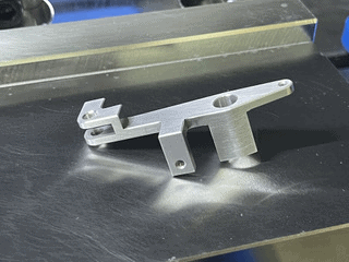
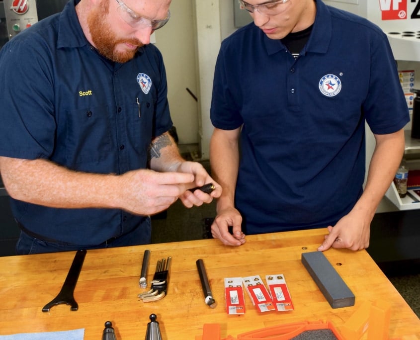
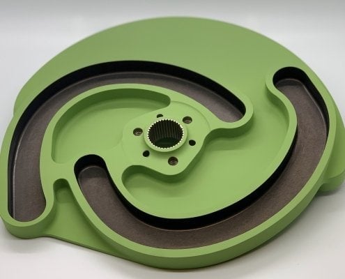
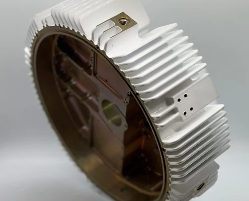
Located in northern California, Olson Manufacturing specializes in handcrafted, customizable golf products that are made with utmost attention to detail from the highest quality materials. Logan Olson, its owner, was introduced to the game of golf by his grandparents at a young age and fell in love with the sport, especially how individualized it is, and how one’s own effort and dedication is paramount. It is because of this love of golf that Logan began designing, and making, his own putters. Soon after, Olson Machining was born.

Now with years under his belt, Logan took time to reflect about Olson Manufacturing, his passion for golf, high-quality tooling, and where his inspiration for his designs originated.

Photo Courtesy of: Logan Olson, Olson Manufacturing

How did you get started and learn how to machine?

I got started in manufacturing coincidentally with making putters: A project that went from a solely digital design to learning a CAD program. It turned into something I wanted to bring into tangible space. A friend of mine introduced me to a manual machinist that had a small machine shop at his house. He had just purchased a personal hobby-sized CNC machine and was kind enough to let me hobble my way through learning the fundamentals of machining on it to design a putter. A year later, I held a barely recognizable chattery mess of a putter and my journey was just beginning.

Where does your passion for golf come from?

I was introduced to the game of golf early on by my grandparents. The individual nature of the game, surrounded by the need to depend on your own effort and dedication as a means to success, has really paved the way for me as a business owner. The need for honesty and integrity, even when it might be easier to take the other road out, has allowed me to stick through the challenging aspects of creating a machine shop and allow my business to thrive in this fast pace, ever-changing world.

What is the inspiration in your designs?

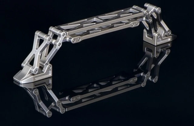
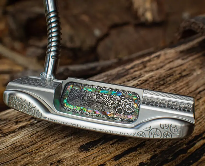
From a design aspect, my number one priority is to do my absolute best to execute the task of creating the best putter I can for the end-user. Customization, additional design aspects, as well as other details, are a welcome addition to a putter that will perform at the highest level. When it comes to the design of creating a custom build, I try to forget that the piece I am working on is a putter altogether and pull my inspiration from other places and different crafts.

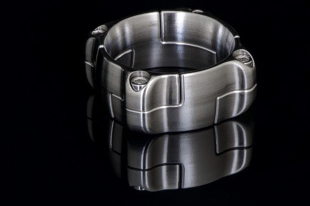
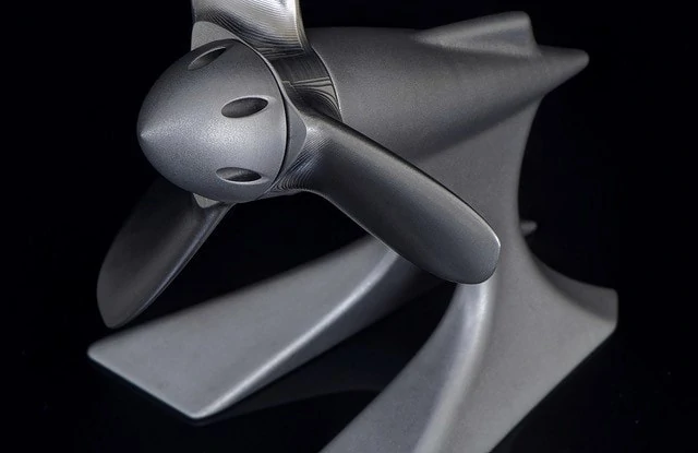
It’s always fun when people ask what I do as a machinist to tell them I make golf clubs. There’s always a hesitant humorous laugh as they respond with an, “oh that’s nice, or good for you”. That always seems to change as soon as I show them what I actually make.  The following response is usually more on the stream of “you seriously make these, or wow, that’s not at all what I expected.” The detailed craftsmanship of sword makers, clockmakers, and jewelers is where I try to pull my main inspiration from.

 I do a lot of commissioned work for customers ordering a specific putter that they themselves design, however, I think my true voice as an artist and machinist lies with the putters I make where the designs can flow out of my own imagination with no guidelines or restrictions.

What is your favorite putter you’ve designed?

I’ve had the opportunity to create a ton of really cool and unique projects in my years as a putter maker. It’s really hard to pick out a favorite. I try to say that my favorite putter I’ve ever made is the one I’m currently working on or excited about. I could probably make a list of the top 20 maybe, but picking an individualistic favorite would be tough.

Who is the most famous contact that you have worked on a project with?

I’ve been lucky enough to work with a handful of professionals on the PGA tour as well as the LPA tour and Web.com tours. Feedback from this caliber of players is really the driving force of development for what I do. They can offer some of the most keynotes that help drive changes every year. I have a hard time picking apart a favorite project, but every time a professional golfer comes aboard I always seem to learn something new.

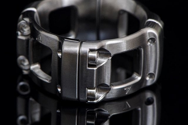
What sets Olson Manufacturing apart from the competition?

In a world where mass production and system efficiency control the consumer market, utilizing old world craftsmanship in companion with cutting edge technology, I can create one of a kind personalized and unique products. That’s not a touch you can find buying something off of a shelf. Knowing that only 1 pair of hands might have spent hours, days, even weeks just creating a putter, I think is something a person holds value to once they acquire one of my putters.

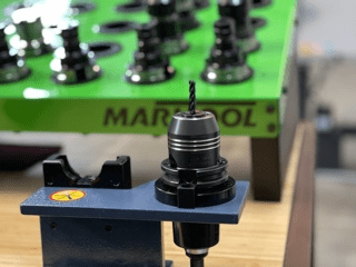
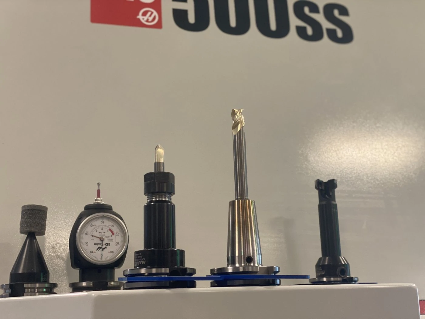
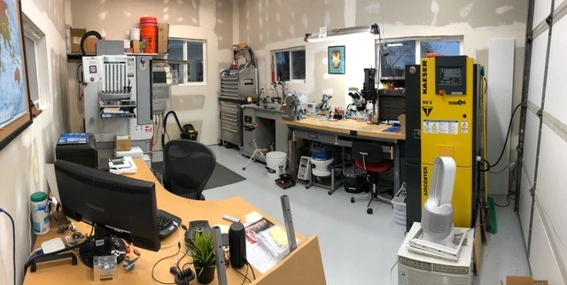
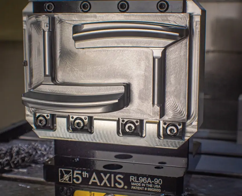
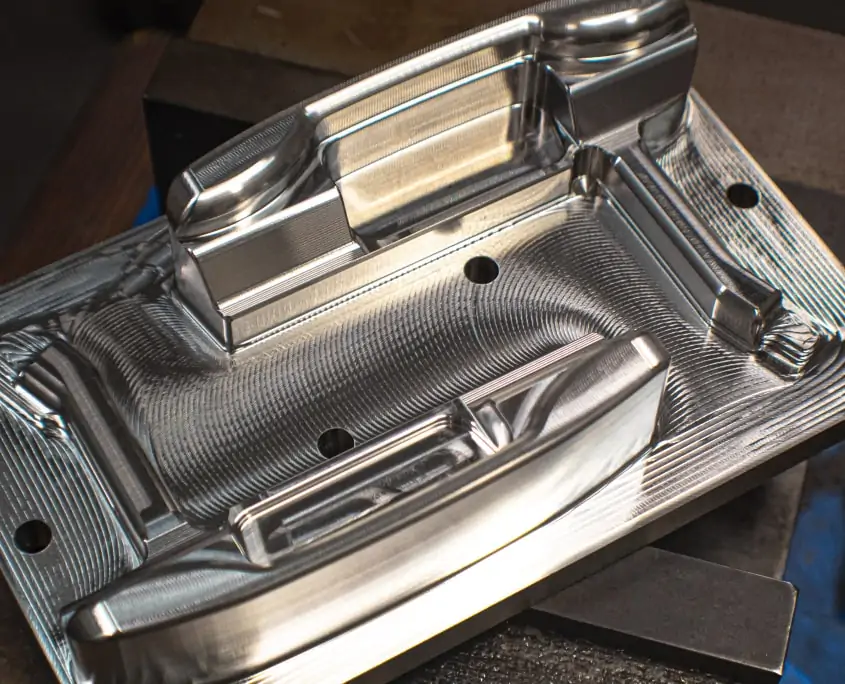
What machines do you currently have in your shop and what materials are you machining?

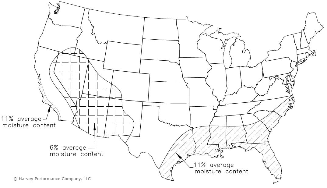
I use all vertical mills at my shop. With the exception of one of my largest machines, having a 4th axis. Everything I run is all 3 axis machining. I really cut everything under the sun. The bulk of my machining consists of stainless steel, mild alloy carbon steel, and aluminum, for fixture making. However, with that said, I do a very large amount of copper as well. The bulk majority of my inlay work is done in superalloys and some exotic blends such as Zirconium-Titanium alloys, Titanium Damascus (Timascus), pre-hardened high carbon Damascus steels, mother of pearl, bronze, and a handful of other materials.

Why is high quality tool performance important to you?

When I’m working in an environment where the part I am making is a one-shot kind of deal or the material is incredibly hard to get/ expensive, not having the ability to remake the part is why customer support and applications engineers are indispensable. When you’re off purchasing a cheap tool from an unknown company you are unlikely to be able to pick up the phone and say “hey, I’ve got a .030” tool going 1” deep in titanium, this tool can’t break haha can you help me out?”

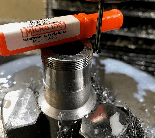
I can count back just in the last year at least a dozen times I’ve spoken with a Harvey Tool rep on one of my micro tools for a cutting recipe recommendation for an application that kept me out of the dog house. I think we could all talk about coating, cutting life, and tool performance all day long, but I could argue that being able to make a phone call and have an engineer reassure you something will work, is the most important thing of all when it comes to quality tool performance.

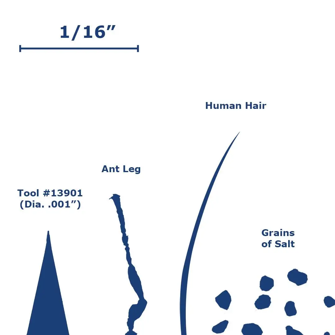
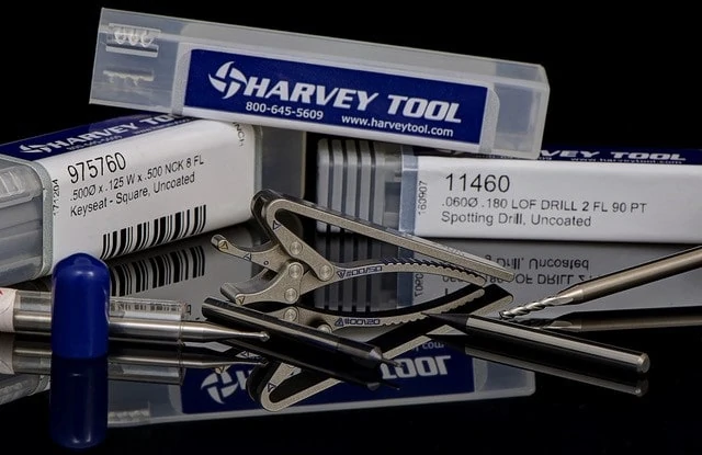
What is the smallest Harvey tool you have used and the largest Helical tool?

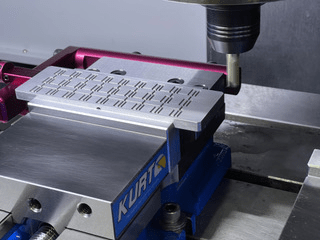
I’ve used a .02” diameter 3 flute tool for stainless and carbon steel, which would likely be the smallest. I regularly store a .04” tool in my tool changer for pocketing on small inlay work. I used to be scared to sneeze on them in fear of them breaking, now they’re as dependable as any tool in my library and I require them daily for all kinds of machine work. The largest tool I run from Helical is a 6 flute ½” endmill for HEM roughing. I find that’s really as large as I need to go.

If heavier cutting is necessary I’ll lean on an insert tool. I really think some people would be amazed though, at the MRR you can get with a ½” tool. These modern toolpaths are incredibly powerful in comparison to some of the older style machining strategies. Give me a ½” tool in stainless full depth at 250 inches a minute and I can move some metal.

Can you talk about a time that Harvey Tool or Helical products really came through and helped your business?

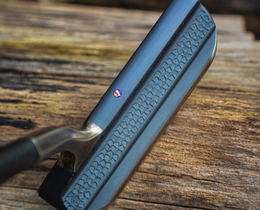
This would go back to one of my earlier answers for the customer support argument. I was running a billet of pre-hardened Damascus steel for a putter I was making. I don’t know if you’re familiar with Damascus at all, but if you picture high carbon steel blended, smashed, and forged together with a nickel alloy, then hardened, I think you can paint a picture. Oh yeah, and nickel alloys are famously fun to machine… think Inconel, Monel, and Hastelloy… fun stuff. So take that billet and make a putter out of it haha.

Anyways, this stuff is harder than a coffin nail and is eating my 80 dollar endmills for breakfast like it skipped dinner the night before. I was down to my last ½” tool that could do the machine work on this putter and didn’t know what I was going to do. I called up Helical, and an applications engineer not only gave me a recipe that ended up saving me but sent me the skew for a tool that worked way better than the one I had in the spindle. I ordered a package of them, and ever since that day, they are my go-to in Damascus.

If you could give one piece of advice to a new machinist ready to take the #PlungeIntoMachining, what would it be?

My biggest piece of advice would be to learn as much as you can. In today’s world, the internet is an incredibly powerful tool and platform for the machining community. There is basically a video out there somewhere you can watch that can probably answer any question you might have. It’s insane. I’m 24 years old and started as a machinist at 19-20. There is absolutely no way I could have gotten to where I am today without countless hours of YouTube scrolling and video binge-watching. It’s great stuff and you should soak it in like a sponge as fast as you can. 30 years ago the machinists would look at the stuff we are doing today and call it Wizardry. We truly are living in an incredible time. Live, learn and love what you do.

To see more of Logan and Olson Manufacturing, you can follow him on Instagram @olsonmfg

Defiant CNC – Featured Customer

Featured Image Courtesy of Jeremy Taylor, Defiant CNC

Twenty years ago, Jeremy Taylor worked as a Tool and Die Apprentice and was well on his way to earning his Journeyman Certification, when he fell in with the wrong crowd and found himself in trouble, criminally. As a result, he found himself facing a lengthy prison sentence but was determined to make his time incarcerated as constructive as possible. During his sentence, he earned his undergraduate and MBA degrees, taught himself Spanish and Italian, and used his limited access to computers to stay updated on all things CNC machining, including the evolution of tool making and advanced manufacturing.

Today, Taylor owns Defiant CNC, a 2-year-old machine shop located in Orlando, Florida, that specializes in performing a wide variety of machining operations, including CNC Milling, CNC turning, laser engraving, finishing, quality control, CAM/CAD, inventory management, technical drawings, and ERP services. Defiant CNC machines everything from components for underwater welding robots to tools for helicopter repair kits, to even tools for pastry decorating and jewelry making.

Along with owning his business, Taylor also spends his time working with The Community, a company that focuses on preparing prisoners to reenter society.

We spoke with Taylor to learn more about how he changed his life’s trajectory; his new business; the ERP system he built, himself; and what he values most in CNC tooling, among other topics.

Photo Courtesy of: Jeremy Taylor, Defiant CNC

How did you first get started in machining?

I started off as a Tool and Die Apprentice. I was making tremendous progress towards my Journeyman Certification until I got myself into trouble. I had done a great job of learning very sophisticated toolmaking techniques and CNC programming/machining. Unfortunately, when I was a few months away from obtaining my journeyman’s card, I was incarcerated for 14 years. However, I utilized that time to significantly change my life trajectory. While in prison, I taught myself Spanish and Italian, kept as up to speed as I could (given very limited access to computers) on the evolution of tool making, CNC machining, advanced manufacturing, computer hardware, and software, completed both an undergraduate degree and an MBA via a mixture of mail and online access.

Today I am a completely different person than the one who wasted the great opportunities I had before my imprisonment. Somewhere along the line during the time when I was 18-19 or so, I fell in with the wrong people and took a path that led to me wasting what should have been the best years of my life. Rather than give up, I used that time while confined to continue my education and prepare myself for a productive role in society after my release. Getting back into machining played a huge role in my current success. Defiant CNC has only been in business for a little over two years, but the best is yet to come.

Photo Courtesy of: Jeremy Taylor, Defiant CNC

What machines are in your shop?

Defiant CNC currently has 4 mills: Doosan DNM 4500, Chevelier QP 2040, Toyoda Stealth 1365, and a Manual Bridgeport Mill. We use Fusion 360 on all of our milling machines. We also have 5 lathes: Emco Maier 365 Y, Miyano BND-51S, Miyano BND-20S5, Miyano BND-34S. and a Miyano BND-42S. Finally, we have our two support machines, a Cosen MH-1016JA Bandsaw and a Boss FMS Laser for Desktop Fiber Marking.

What industries have you worked with?

We have worked with a large variety of industries, including aerospace, defense, automotive, commercial, and medical. Working in these industries allows us to machine in all different materials: Aluminum (7075, 6061, and 2024), Stainless Steel (303, 304, and 316), and Steel (1018, 4140, and 1045).

Photo Courtesy of: Jeremy Taylor, Defiant CNC

What sets Defiant CNC apart from the competition?

We provide an array of machining-related services including milling, turning, CAD design, engineering, and laser engraving in-house. We also provide a number of services through vetted partners such as heat treating, welding, and plating. However, what sets us apart from the rest of the competition is the Enterprise Resource Planning (ERP) system that I built, which is customized specifically for our shop. Not only does it allow us to streamline our operations, but it also allows us to give that something extra to our customers. I create portals and give our customers access to all their past and present jobs with us. They can check the status of any of their jobs as they move through the production process. We take just as much care managing every aspect of the business as we do machining parts.

Typically in small-to-medium-sized shops, the data structure is to create a series of customer-job-part revision folders, and put the customer data there. This data structure is rarely planned for growth. I created an Enterprise Resource Planning (ERP) system using Airtable, along with other API-friendly applications, because the software has Product Data Management (PDM) built into it. PDM is the architecture of the data storage system which, in a nutshell, is the organization, storage, and retrieval of any data that might be tied to a manufacturing process. Since Airtable has a built-in PDM system, we are able to store all our CAM files, G-code, setup documents, tool data (where we log important data about our Helical and Harvey tools), fixture data, and any other data that needs to be tied to a step for making a part. We now have a place to bring together product data (images, instructions, inventory, links, etc), customer information (CRM data), data on sales, marketing development and deployment, a schedule, and more, all in one place. All of the integrations and automations that I built saves hours of manual work and prevents a multitude of mistakes.

Photo Courtesy of: Jeremy Taylor, Defiant CNC

What is your favorite job you have worked on?

I just finished a production run on a job where I completed 12 pieces of two different parts out of hardened 17-4 stainless from start to finish. The cycle time was just over four hours. Each part required three operations after the stock was sawed and heat treated. I designed, modeled, and made two sets of fixtures for each operation in order to load one set while the other was being machined.

When have Harvey or Helical products helped your business?

A majority of the endmills that we stock are Harvey Tool and Helical products. We utilize Fusion 360, which has a tool library full of Harvey Tool and Helical products. About a week ago, we purchased some Harvey Tool flat bottom endmills which saved substantial time on a large production run because we no longer had to circular interpolate a hole. Whenever we are in a pinch and need a tool quickly, Helical Solutions and Harvey Tool always come through.

Photo Courtesy of: Jeremy Taylor, Defiant CNC

Why is high quality tooling important to you?

High quality tools allow us to spend more time machining and less time changing tools. Our go-to tool is Helical’s 3 flute – 40-degree helix with ZPlus, whether we need 1/8 end mills or 5/8 endmills, they get the job done.

What advice do you have for others who want to try High Efficiency Milling?

Consider the material that you are cutting. Consult with your tooling vendor and/or documentation on their website to obtain a starting point and go from there. Helical Solutions has great information on their website and on their social media accounts, with regard to their products. It is worth consulting these sources when utilizing their tools.

Photo Courtesy of: Jeremy Taylor, Defiant CNC

If you could give one piece of advice to a new machinist ready to take the #PlungeIntoMachining, what would it be?

Learning needs to be continuous. Don’t just expect to learn everything that you need to know in one place. Constantly increment your skills in every aspect of machining.

Is there anything else you would like to share with the “In The Loupe” community?

I am grateful for the opportunity to talk about my experiences with Harvey Tool and Helical products and my business. I use Harvey Tool and Helical products because they work well. I will continue to document my usage of their products on my website DefiantCNC.com, as well as my company’s social media accounts (@defiantcnc on Instagram, LinkedIn, and Facebook). Be sure to check them out.

Photo Courtesy of: Jeremy Taylor, Defiant CNC

Workshops for Warriors – Featured Customer

Featured Image Courtesy of Workshops for Warriors

In 2008, Hernán Luis y Prado, a United States Navy officer, noticed his fellow service members looking for a successful path in life after service. Hernán decided he needed to make a change. He set out to make a difference for his fellow service members by starting Workshops for Warriors, a state-licensed, board governed, fully audited, nonprofit school. Its mission is to provide quality training, accredited educational programs, and opportunities for its students to earn third-party nationally recognized credentials to enable Veterans, transitioning service members, and others to be successfully trained and placed in their chosen advanced manufacturing career field.

We had the honor of speaking with Marine Veteran Scott Leoncini, an instructor at Workshops for Warriors, about the accomplishments and amazing work Workshops for Warriors does for our Veterans.

What Does Workshops for Warriors Offer for Our Veterans?

Workshops for Warriors offers two primary tracks of training, both taught by Veterans: welding and machining, Scott explained. After choosing a track, students become a part of the 16-week accelerated program. Those with only a minimum of four months and one nationally-recognized certification can walk across the shipyards and gain employment. Workshops for Warriors remains committed to providing free training to Veterans who do not have access to living-wage jobs. U.S. Veterans often face challenges as they transition to civilian life, including significant barriers to civilian employment. In addition to the hard technical skills, our students are also learning soft skills such as attitude, communication, work ethic, teamwork, time management, problem-solving, critical thinking, and conflict resolution.

A proven path into a rewarding career can eliminate problems like unemployment, homelessness, broken families, and suicide. The problem of Veteran unemployment does not have easy, short-term solutions. Workshops for Warriors is uniquely positioned to expand proven innovative techniques to give Veterans marketable employment that will allow them to build careers and families. 

How Did You Find Workshops for Warriors and Become an Instructor?

After I left the Marines in 2009, after serving two tours in Iraq as a combat engineer, I desired an action-packed career. I thought my best option was to start a career in law enforcement. I got a job at a security company and worked there for a few years. During this time, a close friend of mine tragically passed away in a helicopter crash, leaving behind his pregnant wife. This made me reevaluate my current life with my wife and two children. I decided I didn’t need that action-packed career, and that my family comes before anything.

Another friend of mine actually told me about Workshops for Warriors and how it was giving him career skills in welding, and he talked about a machining program. When I showed up, I had no idea what was in store for me. I started learning all about CNC machines, and how to program and run these things. It was eye-opening and I was having a great time. After my first semester, I was asked to become a teacher’s assistant and I’ve been teaching here now for almost five years.

Where Does Your Passion for Teaching Come From?

I love teaching Veterans and helping them transition so they don’t have to go through the same five years I did of, “What am I going to do with my life?” I’ve gone through the same situation a lot of the people coming to us are currently in.

I think that there are three fundamentals that anyone looking for a career or path can apply to their lives and be successful. You have to show up on time, you have to work hard, and you have to be willing to learn. I didn’t know anything about machinery when I first got into this field. When I went through it as a student myself, I applied those three things to my work habits, and now I’m an instructor. I had pigeonholed myself for a long time. But you have to recognize that there’s always something else, something up next and that’s what I want to help teach the Veterans who come through here.

What Courses Does Workshops for Warriors Provide?

We offer many different courses, including CAD courses in Solidworks and CAM courses in Mastercam, and we offer welding courses for Gas Metal and Flux Cored Arc Welding. We also offer advanced training in Flowmaster Programming and Waterjet Operation, 3D Printing, and Robotics. With these courses, we offer many credentials to start a real career. The machining program is accredited by the National Institute for Metalworking Skills (NIMS). NIMS is recognized by the United States Department of Education. The welding program is accredited by the American Welding Society (AWS), which is the worldwide leader in certification programs for the welding industry.

Thanks to private donors, Veterans and transitioning service members are able to become trained and certified in our advanced manufacturing programs. Students can apply to enter one of our programs, or take specific classes that meet their needs.

What Jobs Have You Seen Veterans Acquire After Workshops for Warriors?

We have seen many success stories from Veterans once they leave Workshops for Warriors. One Veteran, in particular, visited us in search of direction in 2019. The machining program had one spot left for the semester, so he took it. He is now certified in machining and welding. He entered a job market that was struggling after his graduation. But he still had a job lined up with 5th Axis Machining in San Diego. His future plans are to own his own business to support his family.

How Could People Help Support Workshops for Warriors?

They can donate directly to us on our website, or on our Facebook page. Or, people looking to help support us can reach out to us by email, [email protected], or by calling us at 619-550-1620, with any questions. We also accept equipment donations for each program, welding, and machining. You can also support us by following on Facebook, Instagram, Twitter, LinkedIn, YouTube, or our newsletter.

What Advice Would you Give to Anyone Looking to Start a Career Path?

After leaving the service, I fell into a depression. I kept thinking, “I’ll never be as good as I was back then.” It was hard to not have “Marine” be the primary part of my identity, so I became blinded by my obsession with still being the superhero kicking down doors. Don’t paint yourself into a corner. Be flexible and make sure to show up on time, work hard, and be willing to have an open mind and ready to learn. Test your comfort zone. When I left the service, I only knew how to be the man with the gun. Workshops for Warriors gave me a chance to be more than that – it gave me a direction in life. I now get to do what I love and help my fellow Veterans.

To learn more about Workshops for Warriors and their mission you can visit their website or follow them on Instagram, Facebook, LinkedIn or Twitter.

Heavy Duty Racing – Featured Customer

Featured Image Courtesy of Pete Payne, Heavy Duty Racing

Heavy Duty Racing is a manufacturing company based in Stafford, VA, that specializes in motocross, off-road motorcycle suspension, and 2-stroke engine modification. Its owner, Pete Payne, grew up racing motorcycles. Later in life, he even taught classes on how to race. Simply, Motocross and motorcycles became Pete’s passion.

Pete always looked for ways to enhance his motorcycle’s engine, but quickly realized that no shops in his area could design what he was looking for. To get access to the parts he would need, he would have to rely upon companies from far away, and would oftentimes be forced to wait more than three weeks for them to arrive. Because of this, Pete decided he would need to take part manufacturing into his own hands. He purchased a manual lathe, allowing him to make modifications to his two-stroke engines exactly how he wanted them. Quickly thereafter, Heavy Duty Racing was born.

Pete discussed with us his love of racing, how he first got into machining, the parts his shop has designed, and tips and tricks for new machinists.

Pete Payne Heavy Duty Racing
Photo Courtesy of: Pete Payne, Heavy Duty Racing

How did you get started in machining?

Since I was a kid I have been riding motorcycles and racing motocross. I went to a tech school in the ’80s and learned diesel technologies. When I realized nobody in this area could help design the engines I wanted to make, I decided I needed to learn how to do it myself. I have a friend, George, who is a retired mold and die maker that also worked on motorcycle engines, I asked him for some advice on how to get started. George ended up teaching me all about machining and working on engines. I really learned from failures, by trying new things, and doing it every day. I started Heavy Duty Racing in 1997 and we have been modifying and designing the highest performing engines since then.

turning motorcycle part on lathe
Photo Courtesy of: Pete Payne, Heavy Duty Racing

What machines and softwares are you using in your shop?

We currently have a Thormach PCNC 1100 and a Daluth Puma CNC Lathe (we call it The Beast, it’s angry and grumpy but it gets the job done). We also have a Bridgeport Mill, Manual Lathe, and a Tiggwell. When we were choosing software to use, they had to be easy and quick to learn. We weighed our options and decided to use Autodesk Fusion 360 about 5 years ago. We mostly machine cast iron and steel since most engines are made from those materials.

What sets Heavy Duty Racing apart from competitions?

We have a small hands-on approach and treat every part with care. We don’t have a cookie-cutter process so we are very flexible when it comes to customer needs. Since each part is different, we don’t have set prices and have custom quoting on each part. We value our customers and tailor every build to the rider, based on the weight, fuel, and skill level of the rider. We make unique components for each rider so they can have the best experience when they hop on their bike. We are just focused on letting people do what they love.

metal racing parts made by Heavy Duty Racing
Photo Courtesy of: Pete Payne, Heavy Duty Racing

What is the coolest project you have worked on?

In 2016, MX Tech Suspension in Illinois gave us the opportunity to build an engine for them to display at their event. We got to go to California to watch them demo the engine in front of thousands of people. It was very nerve-racking to watch it live but the experience was amazing. The engine was later featured on the cover of Motocross Action magazine. It was very cool to see something we dedicated so much hard time toward get that much recognition.

Why is high quality tooling important to you?

We are making really difficult machine parts so we need tools that can last. Micro 100 tooling lasts and does the job. The thread mills we use are 3-4 mm and 14 mm and they last longer than any competition out there. The thread mills do not chip like the competition and the carbide is super strong. Breaking a tool is not cheap, so to keep one tool in the machine for how long we have has really saved me in the long run. We found Micro 100 one day looking through our distributor’s catalog and decided to try some of their boring bars. After about 5 holes, we realized that these tools are the best we have ever used! Micro has had everything I’ve been looking for in stock and ready to ship, so we have yet to need to try out their custom tools.

Most engine tolerances are no more than .0005” taper. You need the tooling to hold tight tolerances, especially in engines. Just like with tooling, minimizing vibration is key to getting the engine to last longer. We need tight tolerances to maintain high quality and keep engines alive.

machined metal racing part
Photo Courtesy of: Pete Payne, Heavy Duty Racing

If you could give one piece of advice to a new machinist ready to take the #PlungeIntoMachining, what would it be?

The same advice I’ve given to my son: Don’t be ashamed to start from the bottom and learn from the ground, up. Everybody wants to make cool projects, but you need to learn what is going on around you to master the craft. Learn the processes and follow the steps. It’s very easy to break a tool, ruin a part, or even hurt yourself. Don’t be scared of quality tools! Buying the cheap stuff will help you with one job, but the quality tools last and will save you in multiple situations.

Follow Heavy Duty Racing on Instagram, and go check out their website to see more about them!

Achieving Success in CNC Woodworking

Developing a Successful Cutting Direction Strategy

There are a number of factors that can affect the machining practices of wood in woodworking. One that comes up a lot for certain hardwoods is the cutting direction, specifically in relation to the grain pattern of the wood. Wood is an anisotropic material. This means that different material properties are exhibited in different cutting directions. In terms of lumber, there are different structural grades of wood related to grain orientation. If the average direction of the cellulose fibers are parallel to the sides of the piece of lumber, then the grains are said to be straight. Any deviation from this parallel line and the board is considered to be “cross-grain”. Figure 1 below depicts a mostly straight grain board with arrows indicating the different axes. Each of these axes exhibits different sets of mechanical properties. Because of these differences, one must be conscious of the tool path in woodworking and minimize the amount of cutting forces placed on the cutter in order to maximize its tool life.

straight grain wood board with woodworking axes
Figure 1: Mostly straight grain board with arrows indicating different axes

Cutting perpendicular to the grain is known as cutting “across the grain” in woodworking. In Figure 1 above, this would be considered cutting in the radial or tangential direction. Cutting parallel to the grain is known as cutting “along the grain” (longitudinally in terms of Figure 1). The closer you are to cutting at 90° to the grain of the wood in any direction, the larger the cutting force will be. For example, a tool with its center axis parallel to the tangential direction and a tool path along the longitudinal direction would have less wear than a tool with the same center axis but moving in the radial direction. The second type of tool orientation is cutting across more grain boundaries and therefore yields greater cutting forces. However, you must be careful when cutting along the grain as this can cause tear-outs and lead to a poor surface finish.

The Proper Formation of Wood Chips With CNC Woodworking

When cutting wood parallel to the grain, there are three basic types of chips that are formed. When cutting perpendicular to the grain, the chip types generally fall into these same 3 categories, but with much more variability due to the wide range in wood properties with respect to the grain direction.

Type 1 Chips

Type 1 chips are formed when wood splits ahead of the cutting edge through cleavage until failure in bending occurs as a cantilever beam. A large force perpendicular to the shear plane is produced, causing the wood ahead of the cutting edge to split, forming this tiny cantilever beam. When the upward force finally exceeds the strength of this tiny beam, it breaks off.  These types of chips cause comparatively little wear compared to types 2 and 3, as the material is splitting before coming in contact with the pointed edge. End mills with either extremely high rake or very low rake angles often produce type 1 chips. This is especially true when machining against grain slopes that are greater than 25°. Woods with moisture content less than 8%form discontinuous chips and are at a higher risk of tear-out.

Type 2 Chips

Type 2 chips are the most desirable of the three types in terms of surface finish. They are a result of material failure along a diagonal shear plane, extending from the cutting edge to the workpiece surface. Type 2 chips form when there is a proper balance between the properties of the wood, cutting parameters, and cutter geometry. Woods with a moisture content between 8% and 20%have a much higher chance of forming continuous type 2 chips while leaving a good surface finish.

Type 3 Chips

The last type of chip forms when the rake angle of a cutter is much too low. In this scenario, the cutting force is almost parallel to the direction of travel. This causes a soft material, such as wood, to be crushed rather than sheared away, leaving a poor surface finish. Generally, the surface left behind looks like tiny bundles of wood elements, a surface defect commonly known as “fuzzy grain.” This type of chip occurs more frequently in softwoods as the crushing situation is compounded in low-density woods.

types of wood chips in woodworking
Figure 2: Different types of wooden chips

Extending Tool Life When Woodworking

Speeds & Feeds Rules of Thumb

There are several different categories of tool wear that occur when cnc woodworking. General rules of machining still apply as RPM has the greatest influence on wear rate. Over-feeding can increase tool wear exponentially and also cause tool breakage. As with most machining operations, a balance between these two is essential. If you are looking to increase your productivity by increasing your speed, you must increase your feed proportionally in order to maintain a balance that keeps the tool properly engaged in the material.

Proper Management of Heat

When cutting tools are exposed to high heat, they begin to wear even faster, due to corrosion. The cobalt binder within most carbide tools on the market begins to oxidize and break free of the cutting edge. This sets off a chain reaction, as when the binder is removed, the tungsten carbide breaks away, too. Different species of wood and types of engineered wood have different corrosive behaviors at high temperatures. This is the most consistent type of wear that is observed when machining MDF or particleboard. The wear is due to the chlorine and sulfate salts found in adhesives as this accelerates high-temperature corrosion.  As with aluminum, when the silica content of a wood increases, so too does its corrosiveness.

Generally, increased tool wear is observed in wood with high moisture content. This trait is due to the increased electro-chemical wear caused by the extractives in wood., Moisture content in wood includes substances such as resins, sugars, oils, starches, alkaloids, and tannins in the presence of water. These molecules react with the metallic constitutes of the cutting tool and can dull the cutting edge. Carbide is more resistant to this type of wear compared to high-speed steel.

Best Coatings for Extended Tool Life in Wood

If you want a longer-lasting tool that will maintain its sharp cutting edge (and who doesn’t), you may want to consider an Amorphous Diamond coating. This is an extremely abrasive resistant coating meant for non-ferrous operations in which the temperature of the cutting zone does not exceed 750 °F. This coating type is one of Harvey Tool’s thinnest coatings, therefore minimizing the risk of any edge rounding and maximizing this edge’s durability.

Avoiding Common Woodworking Mishaps

Tear Out

Tear out, sometimes called chipped grain or splintering, is when a chunk of the wood material being machined tears away from the main workpiece and leaves an unappealing defect where it used to be. This is one of the most common defects when machining wood products. There are many different reasons that tear out occurs. Material characteristics are something to be considered. Tear out is more likely to occur if the grain orientation is less than 20°relative to the tool path, the moisture content of the wood is too low, or the density of the wood is too low. Figure 4 shows the grain orientation angle relative to the tool path. In terms of machining parameters, it can also occur if either the chip load, depth of cut, or rake angle is too high.

woodworking grain in relation to tool path
Figure 4: Example of grain orientation angle relative to the tool path

Fuzzy Grain Finish

Fuzzy grain looks like small clumps of wood attached to the newly machined face and occurs when the wood fibers are not severed properly. Low rake or dull cutting tools indent fibers until they tear out from their natural pattern inside, causing type 3 chips to form, resulting in a poor finish. This can be exacerbated by a low feed or depth of cut as the tool is not properly engaged and is plowing material rather than shearing it properly. Softer woods with smaller and lesser amounts of grains are more susceptible to this type of defect. Juvenile wood is known to be particularly liable for fuzzy grain because of its high moisture content.

fuzzy grain wood finish
Figure 5: Example of a fuzzy grain finish

Burn Marks

Burn Marks are a defect that is particularly significant in the case of machining wood, as it is not generally a concern when machining other materials. Dwelling in a spot for too long, not engaging enough of the end mill in a cut, or using dull tools creates an excessive amount of heat through friction, which leaves burn marks. Some woods (such as maple or cherry) are more susceptible to burn marks, therefore tool paths for these types should be programmed sensibly. If you are having a lot of trouble with burn marks in a particular operation, you may want to try spraying the end mill with a commercial lubricant or paste wax. Be careful not to use too much as the excess moisture can cause warping. Increasing your tool engagement or decreasing RPM may also combat burn marks.

burn marks from wood cutter
Figure 6: Example of burn marks

Chip Marks

Chip marks are shallow compressions in the surface of the wood that have been sprayed or pressed into the surface. These defects can swell with an increase in moisture content, worsening the finish even more. This type of blemish is generally caused by poor chip evacuation and can usually be fixed by applying air blast coolant to the cutting region during the operation.

Raised Grain

Raised grain, another common defect of woods, is when one or more portions of the workpiece are slightly lower than the rest. This blemish is particularly a problem when machining softer woods with dull tools as the fibers will tear and deform rather than be cleanly sheared away. This effect is intensified when machining with slow feeds and the wood has a high moisture content. Variations in swelling and shrinking between damaged and undamaged sections of wood exacerbate this flaw. It’s for this reason that raised grain is a common sight on weather-beaten woods. Work holding devices that are set too tight also have a chance of causing raised grain.

Differentiating Harvey Tool Wood Cutting & Plastic Cutting End Mills

Woodworking Upcut End Mill
Harvey Tool Upcut End Mill For Wood

https://www.harveytool.com/products/material-specific-end-mills/woodMachinists oftentimes use Plastic Cutting End Mills for woodworking, as this tool has very similar internal geometries to that of an End Mill for Wood. Both tools have large flute valleys and sharp cutting edges, advantageous for the machining of both plastic and wood. The main difference between the Harvey Tool plastic cutters and the woodcutters is the wedge angle (a combination of the primary relief and rake angle). The woodcutter line has a lower rake but still has a high relief angle to maintain the sharpness of the cutting edge. The lower rake is designed to not be as “grabby” as the plastic cutters can be when woodworking. It was meant to shear wood and leave a quality surface finish by not causing tear-out.

Harvey Tool’s offering of End Mills for Wood includes both upcut and downcut options. The upcut option is designed for milling natural and engineered woods, featuring a 2-flute style and a wedge angle engineered for shearing wood fiber materials without causing tear out or leaving a fuzzy grain finish. The downcut offering is optimized for milling natural and engineered woods and helps prevent lifting on vacuum tables.

For more help on achieving a successful machining operation, or more information on Harvey Tool’s offering of End Mills for Wood, please contact Harvey Tool’s team of engineers at 800-645-5609.

Understanding Wood Properties for CNC Woodworking Projects

Machinists oftentimes confuse wood for being an “easy to machine material” during CNC Woodworking because of how much softer the material is than metal. In some sense this is true, as you can program wood cutting parameters in CNC Woodworking with much higher feed rates compared to that of most metals. On the other hand, however, wood has many unique properties that need to be accounted for in order to optimize the cutting process for maximum efficiency.

Get the Most Out of Your CNC Woodworking Projects With Harvey Tool’s Speeds and Feeds

Types of Wood for CNC Woodworking

There are 3 main categories of wood for woodworking: hardwood, softwood and engineered wood.

Hardwood

The textbook definition of a hardwood tree is an angiosperm, more commonly referred to as a broadleaf tree. A few examples would be oak, birch, and maple trees. These types of trees are often used for making high quality furniture, decks, flooring, and construction components.

Softwood

A softwood is a coniferous tree, sometimes known as a gymnosperm. These are typically less dense than hardwoods and are therefore associated with being easier to machine. Do not let the name fool you: some soft woods are harder than some hardwoods. Harvey Tool’s Speeds and Feeds Charts for its offering of Material Specific End Mills for Wood are categorized by Janka hardness for this exact reason. Janka hardness is a modified hardness scale with a test specifically designed for classifying types of wood.

Softwood is used to make furniture, but can also be used for doors, window panes, and paper products. A couple of examples are pine and cedar trees. Table 1 lists 20 common woods with their Janka hardness.

Common Name:Janka Imperial Hardness:
Balsa90
Buckeye, Yellow350
Willow, Black360
Pine, Sugar380
Cottonwood, Eastern430
Chesnut, American540
Pine, Red560
Douglas-Fir, Interior North600
Birch, Gray760
Ash, Black850
Cedar, Eastern Red900
Cherry, American Black950
Walnut, Black1010
Beech, American1300
Oak, White1360
Maple, Sugar1450
Apple1730
Cherry, Brazilian2350
Olive2700
Rosewood, Indian3170
Table 1: Janka Hardness of Common Woods

Engineered Woods

Engineered wood, or composite wood, is any type of wood fiber, particle, or strand material held together with an adhesive or binding agent. Although some of these materials are easier to machine than solid woods, the adhesive holding the material together can be extremely abrasive. This can cause premature tool wear and create difficulties when cnc woodworking. It’s important to note that some types of engineered woods are more difficult to machine than others, specifically those with a higher amount of binding material. These types should be programmed with less aggressive speeds and feeds. For example, medium density fiberboard (MDF) if more difficult to machine than plywood, but much easier to machine than phenolic.

stack of medium density fiberboard pieces for cnc woodworking
Figure 1: Example of Medium Density Fiberboard

Properties of Wood

Grain Size

Technically speaking, wood can be considered a natural composite material as it consists of strong and flexible cellulose fibers held together by a stiffer glue-like matrix composed of lignin and hemicellulose. If you think in terms of construction, the cellulose fibers would be the steel rebar, and the concrete would be the lignin and hemicellulose. Wood with large cellulose fibers are considered to be coarse-grained (oak and ash). Woods that have smaller and fewer fibers are considered fine-grained (pine and maple). Softwoods tend to be fine-grained and are therefore stereotyped as being easier to machine since they do not have as many strong fibers to shear. It’s important to note that not all hardwood trees are coarse grained and not all softwood trees are fine-grained.

diagram of natural wood fibers for cnc woodworking
Figure 2: Simplified diagram of fibers that constitute natural wood. The cellulose fibers run vertically in this depiction.

Moisture Content (MC)

Moisture content (MC) is one of the most important variables to consider when machining wood. An extremely common problem with building anything with wood is its tendency to warp. Moisture variability in the air inevitably affects the moisture content within the wood. Any change in moisture content (whether an increase or a decrease) will disturb the shape of the workpiece. This is why one must take into account what type of moisture a product will be exposed to in its final resting place.

Equilibrium Moisture Content (EMC)

Equilibrium moisture content (EMC) occurs when wood has reached a balance point in its moisture content. Interior EMC values across the United States average at about 8%, with exterior values averaging around 12%. These values vary around the country due to the differences in temperature and humidity. For example, the southeastern United States have an average interior EMC of 11% while the southwest averages about 6% (excluding the coastal region). It’s important to consider what region and application the final product is going to encounter so that the wood with the correct moisture content can be selected before machining. Most species of flat-grain wood will change size 1% for every 4% change in MC. The direction of warping depends on the grain orientation.

United States map showing average regional indoor EMC
Figure 4: Average regional indoor EMC

Generally, power requirements for an operation rise with increasing moisture content, mainly because of the surge in density. Density of wood increases with rising MC. The additional power may be necessary to push a heavier chip out of the cutting zone during CNC Woodworking. It’s worth noting that, like synthetic polymers, wood is a viscoelastic material that absorbs energy as it becomes wetter. The proportional limit of its mechanical properties intensifies as MC increases.

When machining some types of wood, cutting region temperature will surge with increasing MC, but in other species it will decline. Be safe and avoid rapid tool wear by decreasing SFM when machining a wood with a moisture content above 10%. Harvey Tool Speeds and Feeds Charts suggest a decrease of 30 per MC percentage point. As always, though, it depends on the type of wood being machined and the type of operation being performed.

Temperature change is not the only reason higher moisture content is associated with rapid tool wear. Moisture within wood isn’t just associated with water, but also with resins, sugars, oils, starches, alkaloids, and tannin present within the water. These substances react particularly well with high speed steel, and to a lesser degree with carbide.

Knots and Their Effect on CNC Woodworking

A knot is a portion of a branch or limb that has become incorporated in the trunk of a tree. The influence of knots on the mechanical properties of wood is due to the interruption of continuity and change in direction of wood fibers associated with it. These properties are lower in this portion of the wood because the fibers around the knot are distorted and lead to stress concentrations. “Checking” (cracking due to shrinking) often occurs around knots during drying. Hardness and strength perpendicular to the grain are exceptions to generally lower mechanical properties. Because of these last two exceptions, woodworking machining parameters should be reduced when encountering a knotted portion of the workpiece to avoid shock loading.

typical natural wood knot in hardwood
Figure 5: Photo of a typical knot

Rennscot LLC – Featured Customer

Featured Image Courtesy of David Bamforth, Rennscot LLC

David Bamforth is the founder and CEO of Rennscot LLC, a manufacturing company based out of Woburn, Massachusetts, which was created to meet product design demands of both individual and commercial clients. From idea to prototype, and eventually to final product, Rennscot LLC prides itself on its ability to make part ideas come to life. David took some time to talk with us about Rennscot LLC, his company’s machining capabilities, and much more.

Assortment of end mills and tool holders at Rennscott LLC
Photo Courtesy of: David Bamforth, Rennscot LLC

What capabilities does your shop have?

We are mostly a mill shop with two verticals and one 5-axis machine. We also have a small bar fed lathe, a larger sub-spindle live-tooling lathe, and some design tools like a Faro Design Scan Arm. We work predominantly with aluminum, but sometimes see brass, stainless, titanium, and steel alloy jobs come through. We use Fusion 360 for everything and currently all 4 of our machines are Haas.

What sets Rennscot LLC apart from the competition?

We are a bit different from most shops because, in addition to machining services, we also offer design services. A lot of our jobs are won because we are a one-stop-shop from idea to producing the final product. Recently we have been making a lot of parts for vehicle restoration. Typically, we are just handed a part and asked to reproduce it.

What is your favorite part of the job?

Problem solving and learning new skills. We are a pretty young team and love being challenged by new projects. We also pride ourselves on being pretty innovative with our machining strategies to help reduce lead times and cost for our customers.

cnc machined metal part from Rennscot LLC
Photo Courtesy of: David Bamforth, Rennscot LLC

Where did your passion for automobiles come from?

Like many, I have always been passionate about cars. I have some great memories of going to car shows with my dad and watching any TV show with a car in it as a kid. Nowadays, I spend my personal time taking our shop development car, a Porsche Cayman, to the track.

What is the coolest product you have made?

We have had some pretty unusual characters bring us some really cool projects. Currently, we are working with a guy from Connecticut on laser scanning a model Mercedes C10 Le Mans car that we will CAD model, so a full-sized car body can be reproduced. It’s a really interesting project, trying to take a 1:43 car and blow it up to full size. Eventually, we will help design and manufacture many of the machined components on this car. Also, we once made a custom billet alternator mount in just 5 days for a 996 Porsche GT3 with a Chevy LS engine in it. We really enjoyed being part of that project and the V8 sounded amazing on track!

cnc machined metal part from Rennscot LLC
Photo Courtesy of: David Bamforth, Rennscot LLC

What is the most difficult product you have made?

We once worked on an enclosure for a handheld x-ray machine. The part was only about 1”x 1.25” x4” and only had .040” walls all around. The main pocket was machined with our go-to Helical ¼” reduced shank end mill. It also had #0-80 taps all along the top edge of the enclosure, making for a few broken taps! It was a pain to get dialed in but once the process was proved out it was really rewarding to get consistent good parts off the will.

Why is high quality tool performance important to you?

Once we started using high quality end mills, we immediately saw an improvement in tool life and surface finish. We also really enjoy using tools that are backed by a company that puts out so much information and resources to help its customers out.

When was a time that Harvey Tool or Helical products really came through and helped your business?

We have had several moments when we hit a wall while building a process for a new part, and Helical’s phone support helped us find the perfect tool for the process. The combination of great phone support, having such a vast array of product offerings, and all of the tools always being in stock has helped my business tremendously.

Rennscot LLC machine shop assortment of harvey tool and helical end mills
Photo Courtesy of: David Bamforth, Rennscot LLC

Are you guys using High Efficiency Milling (HEM) techniques to improve cycle times?

Always! All our mills are spec’ed with HSM and 12k RPM spindles, and we take full advantage of this with chip breaking roughers. Honestly, we are so young that we have only ever used HEM techniques, so I’m honestly just confused by companies that don’t use it. Not using HEM is like not driving a car on the highway because it’s too fast.

If you could give one piece of advice to a new machinist ready to take the #PlungeIntoMachining, what would it be?

Machining is probably the most in demand and most satisfying industries that someone can get into now-a-days. There are a lot of companies that are in demand for green machinists who are just eager to learn. I would recommend putting together and sending out a resume to local shops that shows that you have the ability to take on projects and complete them.

If anyone is interested in learning more about what we do our manufacturing website, rennscotmfg.com is a great resource. Also, check us our on Instagram at @rennscot.

How to Optimize Results While Machining With Miniature End Mills

 The machining industry generally considers micromachining and miniature end mills to be any end mill with a diameter under 1/8 of an inch. This is also often the point where tolerances must be held to a tighter window. Because the diameter of a tool is directly related to the strength of a tool, miniature end mills are considerably weaker than their larger counterparts, and therefore, lack of strength must be accounted for when micromachining. If you are using these tools in a repetitive application, then optimization of this process is key.

Size comparison chart with square miniature end mill, ant leg, human hair, and grains of salt
Size Comparison for Harvey Tool’s #13901 Square Miniature End Mill

Key Cutting Differences Between Conventional and Miniature End Mills

Runout

Runout during an operation has a much greater effect on miniature tools, as even a very small amount can have a large impact on the tool engagement and cutting forces. Runout causes the cutting forces to increase due to the uneven engagement of the flutes, prompting some flutes to wear faster than others in conventional tools, and breakage in miniature tools. Tool vibration also impacts the tool life, as the intermittent impacts can cause the tool to chip or, in the case of miniature tools, break. It is extremely important to check the runout of a setup before starting an operation. The example below demonstrates how much of a difference .001” of runout is between a .500” diameter tool and a .031” diameter tool.

chart comparing tool diameter for runout in micromachining with miniature end mills
The runout of an operation should not exceed 2% of the tool diameter. Excess runout will lead to a poor surface finish.

Chip Thickness

The ratio between the chip thickness and the edge radius (the edge prep) is much smaller for miniature tools. This phenomena is sometimes called “the size effect” and often leads to an error in the prediction of cutting forces. When the chip thickness-to-edge radius ratio is smaller, the cutter will be more or less ploughing the material rather than shearing it. This ploughing effect is essentially due to the negative rake angle created by the edge radius when cutting a chip with a small thickness.

If this thickness is less than a certain value (this value depends of the tool being used), the material will squeeze underneath the tool. Once the tool passes and there is no chip formation, part of the plowed material recovers elastically. This elastic recovery causes there to be higher cutting forces and friction due to the increased contact area between the tool and the workpiece. These two factors ultimately lead to a greater amount of tool wear and surface roughness.

chart of edge radius in relation to chip thickness for micromachining
Figure 1: (A) Miniature tool operation where the edge radius is greater than the chip thickness (B) Conventional operation where the edge radius is small than the chip thickness

Tool Deflection in Conventional vs. Micromachining Applications

Tool deflection has a much greater impact on the formation of chips and accuracy of the operation in micromachining operations, when compared to conventional operations. Cutting forces concentrated on the side of the tool cause it to bend in the direction opposite the feed. The magnitude of this deflection depends upon the rigidity of the tool and its distance extended from the spindle. Small diameter tools are inherently less stiff compared to larger diameter tools because they have much less material holding them in place during the operation. In theory, doubling the length sticking out of the holder will result in 8 times more deflection. Doubling the diameter of an end mill it will result in 16 times less deflection. If a miniature cutting tool breaks on the first pass, it is most likely due to the deflection force overcoming the strength of the carbide. Here are some ways you can minimize tool deflection.

Workpiece Homogeny

Workpiece homogeny becomes a questionable factor with decreasing tool diameter. This means that a material may not have uniform properties at an exceptionally small scale due to a number of factors, such as container surfaces, insoluble impurities, grain boundaries, and dislocations. This assumption is generally saved for tools that have a cutter diameter below .020”, as the cutting system needs to be extremely small in order for the homogeny of the microstructure of the material to be called into question.

Surface Finish

Micromachining may result in an increased amount of burrs and surface roughness when compared to conventional machining. In milling, burring increases as feed increases, and decreases as speed increases. During a machining operation, chips are created by the compression and shearing of the workpiece material along the primary shear zone. This shear zone can be seen in Figure 2 below. As stated before, the chip thickness-to-edge radius ratio is much higher in miniature applications. Therefore, plastic and elastic deformation zones are created during cutting and are located adjacent to the primary shear zone (Figure 2a). Consequently, when the cutting edge is close to the border of the workpiece, the elastic zone also reaches this border (Figure 2b). Plastic deformation spreads into this area as the cutting edge advances, and more plastic deformation forms at the border due to the connecting elastic deformation zones (Figure 2c). A permanent burr begins to form when the plastic deformation zones connect (Figure 2d) and are expanded once a chip cracks along the slip line (Figure 2e). When the chips finally break off from the edge of the workpiece, a burr is left behind (Figure 2f).

burr formation mechanism using a miniature end mill
Figure 2: Burr formation mechanism using a miniature end mill 

Tool Path Best Practices for Miniature End Mills

Because of the fragility of miniature tools, the tool path must be programmed in such a way as to avoid a sudden amount of cutting force, as well as permit the distribution of cutting forces along multiple axes. For these reasons, the following practices should be considered when writing a program for a miniature tool path:

Ramping Into a Part

Circular ramping is the best practice for moving down axially into a part, as it evenly distributes cutting forces along the x, y, and z planes. If you have to move into a part radially at a certain depth of cut, consider an arching tool path as this gradually loads cutting forces onto the tool instead of all at once.

Micromachining in Circular Paths

You should not use the same speeds and feed for a circular path as you would for a linear path. This is because of an effect called compounded angular velocity. Each tooth on a cutting tool has its own angular velocity when it is active in the spindle. When a circular tool path is used, another angular velocity component is added to the system and, therefore, the teeth on the outer portion of tool path are traveling at a substantially different speed than expected. The feed of the tool must be adjusted depending on whether it is an internal or external circular operation. To find out how to adjust your feed, check out this article on running in circles.

Slotting with a Miniature End Mill

Do not approach a miniature slot the same way as you would a larger slot. With a miniature slot, you want as many flutes on the tool as possible, as this increases the rigidity of the tool through a larger core. This decreases the possibility of the tool breaking due to deflection. Because there is less room for chips to evacuate with a higher number of flutes, the axial engagement must be decreased. With larger diameter tools you may be stepping down 50% – 100% of the tool diameter. But when using miniature end mills with a higher flute count, only step down between 5% – 15%, depending on the size of the diameter and risk of deflection. The feed rate should be increased to compensate for the decreased axial engagement. The feed can be increased even high when using a ball nose end mill as chip thinning occurs at these light depths of cut and begins to act like a high feed mill.

Slowing Down Your Feed Around Corners

Corners of a part create an additional amount of cutting forces as more of the tool becomes engaged with the part. For this reason it is beneficial to slow down your feed when machining around corners to gradually introduce the tool to these forces.

Climb Milling vs. Conventional Milling in Micromachining Applications

This is somewhat of a tricky question to answer when it comes to micromachining. Climb milling should be utilized whenever a quality surface finish is called for on the part print. This type of tool path ultimately leads to more predictable/lower cutting forces and therefore higher quality surface finish. In climb milling, the cutter engages the maximum chip thickness at the beginning of the cut, giving it a tendency to push away from the workpiece. This can potentially cause chatter issues if the setup does not have enough rigidity.  In conventional milling, as the cutter rotates back into the cut it pulls itself into the material and increases cutting forces. Conventional milling should be utilized for parts with long thin walls as well as delicate operations.

Combined Roughing and Finishing Operations

These operations should be considered when micromachining tall thin walled parts as in some cases there is not sufficient support for the part for a finishing pass.

Helpful Tips for Achieving Successful Micromachining Operations With Miniature End Mills

Try to minimize runout and deflection as much as possible when micromachining with miniature end mills. This can be achieved by using a shrink-fit or press-fit tool holder. Maximize the amount of shank contact with the collet while minimizing the amount of stick-out during an operation. Double check your print and make sure that you have the largest possible end mill because bigger tools mean less deflection.

  • Choose an appropriate depth of cut so that the chip thickness to edge radius ratio is not too small as this will cause a ploughing effect.
  • If possible, test the hardness of the workpiece before machining to confirm the mechanical properties of the material advertised by the vender. This gives the operator an idea of the quality of the material.
  • Use a coated tool if possible when working in ferrous materials due to the excess amount of heat that is generated when machining these types of metals. Tool coatings can increase tool life between 30%-200% and allows for higher speeds, which is key in micro-machining.
  • Consider using a support material to control the advent of burrs during a micromachining application. The support material is deposited on the workpiece surface to provide auxiliary support force as well as increase the stiffness of the original edge of the workpiece. During the operation, the support material burrs and is plastically deformed rather than the workpiece.
  • Use flood coolant to lower cutting forces and a greater surface finish.
  • Scrutinize the tool path that is to be applied as a few adjustments can go a long way in extending the life of a miniature tool.
  • Double-check tool geometry to make sure it is appropriate for the material you are machining. When available, use variable pitch and variable helix tools as this will reduce harmonics at the exceptionally high RPMs that miniature tools are typically run at.
side-by-side view of two end mills comparing variable pitch versus non-variable pitch
Figure 3: Variable pitch tool (yellow) vs. a non-variable pitch tool (black)

TOMI Engineering INC – Featured Customer

Featured Image Courtesy of TOMI Engineering

Since its beginning in 1977, brothers Tony and Mike Falbo have made the focal point of TOMI Engineering to deliver quality, competitively-priced parts on time. TOMI Engineering has earned a reputation through the years as being a world-class manufacturer of precision machined components and assemblies for aerospace, defense, commercial and other advanced technology industries. They are fortunate to have the highest level of engineering, quality and programming personnel on staff, and, with over 40 years in the industry, there isn’t a problem TOMI hasn’t experienced.

With all the years of experience, TOMI Engineering has a lot of knowledge to share. We had the pleasure of sitting down with Tony and Mike Falbo to ask them about their experiences, techniques, tooling and a lot more.

green machined part from Tomi Engineering INC
Photo Courtesy of: TOMI Engineering

How was TOMI Engineering INC started?

TOMI Engineering, Inc. began in 1977 when we (Tony and Mike) teamed up and got a loan from our father to purchase our first machine.  The machine was used in the garage of our parents’ home, which still resides in Tustin, California.  Forty years, 20 current machines, and countless parts later, TOMI Engineering proudly serves the defense, airline, medical and commercial industries.  We machine just about any type of product thrown our way.  Over the years, we have made wing tips for the F16 fighter jet, enclosures for GPS housings, manifolds that help transport fluids, support frames for Gulfstream, cabin brackets for Airbus, ammunition feeders for tanks, and many, many others.

At TOMI Engineering, we aim to be a one-stop shop for our customers.  Once we receive blueprints, we can program, machine, deburr, inspect, process and assemble most parts.  We utilize a mixture of 3-and-4-axis machines in order to increase efficiency, which helps us to cut down costs to our customer.  In our temperature-controlled assembly room, we can assemble bearings, bushings, rivets, nut plates, gaskets and sealants.  We also hope to add additive machining to our repertoire soon.

What machines are you currently using in your shop?

Our 21,250 square foot facility houses 20 CNC machines.  Most of our machines are Kitamura, OKK and Okuma.  The purchase dates of these machines range from 1987 to December of 2019.  With our large machine diversity, we can machine parts smaller than a penny, and as large as 30 x 60 inches. Most of the material that makes its way through our shop is aluminum.  Whether it is 6061 or aircraft grade 7000 series, we aim to have most of our parts be aluminum.  However, we do see a large amount of 6AL-4V titanium, along with 17-4 and 15-5 steel. We are currently utilizing Mastercam 2020 for most of our programming needs and are staying up to date with software upgrades and progression.

Tomi Engineering CNC mill
Photo Courtesy of: TOMI Engineering

What sets TOMI Engineering apart from the rest of the competition?

We believe our greatest asset is our experience.  Here at TOMI, we have been machining parts since 1977.  In those 40-plus years, a lot of parts have come and gone through our doors and we have helped our customers solve a large array of problems.  Most of our machinists have been with us for over 10 years, while some are approaching 20 years!  Our programmers easily boast over 60 years of experience! With so many of our employees working together for so many years, it has really helped everyone to understand what helps us quickly machine our products, while being held accountable to the high standards of AS9100. 

Where did your passion for machining start?

We grew up with machines in our garage and it wasn’t until we needed money to pay for college that our dad realized he could show us the basics of operating a milling machine, which allowed us to pay our tuition while working at home in the evenings and weekends. Machining was more of a necessity than a passion at the time. However, after nearly 40 years in the business, it has been amazing to see the strides in technology from a Bridgeport Mill to the multi-axis lights-out machining that is available today.

My favorite part of the job has always been the flexibility it has allowed me. I had the opportunity to watch my kids grow up and be a part of their lives by going to their school plays, coaching them, and being home at night to help them with anything they needed. Most importantly, I’ve had the opportunity to work with my brother, my business partner, who also shares the same ideals about being with family, so we could always cover for each while the other was gone and spending time with their family. The business would not have worked without both of us understanding the importance of each other’s input. The challenge of running a business keeps me going, and working with all of the different personalities was an added bonus.

machined part from Tomi Engineering
Photo Courtesy of: TOMI Engineering

Who is the most famous contact that you have worked on a project with? What is the most interesting product you’ve made?

At TOMI, we do not work with specific individuals, so we can’t really name drop.  However, a vast majority of our work is for Airbus, Boeing, or the military. So it’s pretty gratifying to say that we supply parts to some of the biggest companies in the world and that our work helps to defend this country.

The most interesting product we have made here at TOMI is a GPS housing for a defense contractor.  This part encompasses everything that we can do at TOMI: precision machining, complex/multi detail assemblies, gasket assembly, and pressure testing fluid transportation components. 

Why is high quality tool performance important to you?

High quality tool performance is important to us in many ways.  Purchasing high quality tools allow us to constantly achieve premium surface finishes, push our machines to the high speeds and feeds that they are capable of, and enjoy noticeably longer tool life.

Every part, day-in and day-out, is different.   Because of our vast array of products, our tools are always changing.  But when we are picking out Helical End Mills for Aluminum, we always go with their 3-flute variable helix cutters, and we have always been happy with them.

machined part from Tomi Engineering
Photo Courtesy of: TOMI Engineering

What sort of tolerances do you work in on a daily basis?

The tolerances we typically work with are ± tenths of an inch, as well as very tight true position cal louts. We can hold and achieve these close tolerance dimensions through our very experienced Mastercam programmers, as well as our superior quality department.  Our quality inspectors have over 30 years of experience in the industry and utilize two Zeiss Contura G2 coordinate measuring machines (CMMs).  While in their temperature controlled environment, the CMMs are capable of measuring close tolerance dimensions and are used to generate data for inspection reports.

Are you guys using High Efficiency Milling (HEM) techniques to improve cycle times? What advice do you have for others who want to try HEM?

Yes, we are using HEM techniques to improve cycle times while roughing to increase our MRR while increasing tool life. If you have CAM/CAD software that supports HEM, then go for it!  Machining Advisor Pro (MAP) is VERY helpful with the suggested speeds and feeds as a starting point.  Over time though, and through experience, we have learned that every single machine is a bit different and often needs a different approach with speeds and feeds.  Start with a smaller than suggested RDOC and physically go out to your machine and see how it sounds and what is going on.  Then, start increasing and find that sweet spot that your particular machine runs well on.  Many programmers in the industry will not take the time to go out and watch how their part is sounding and cutting on the machine and going out and doing that is the best way to really find out what you and the machine are capable of achieving.

If you could give one piece of advice to a new machinist ready to take the #PlungeIntoMachining, what would it be?

Ask questions!  Don’t be afraid to talk to programmers and fellow coworkers about what is trying to be achieved and WHY the programmer is holding tolerances a certain way.  Learn from them and watch what every cutter is doing during your cycles.  The more you learn, the more you can contribute to the machining process and move up in your business.  Sometimes it takes just one good suggestion about the machining approach that can change the set-up process from aggravating to very easy.  Lastly, be open minded to new ideas and approaches.  As we said earlier, there are a ton of ways to make good parts in a constantly evolving industry.

Please take the time to check out the TOMI Engineering INC website or follow them on social media!

Titan Ring Design – Featured Customer

Featured Image Courtesy of Trevor Hirschi, Titan Ring Design

Officially started in 2015, Titan Ring Design is a high quality machine shop that designs rings, as well as mechanical tie clips, art based designs, and freelance custom designs. While working at a machine shop that produced top notch parts for just about every type of field you can imagine, now owner of Titan Ring Design, Trevor Hirschi, noticed that the machining industry is mostly about cranking out a mass quantity of the highest quality parts as quickly as possible. This often resulted in compromised tolerances and part finishes, something Trevor aimed to change. Quality always comes first in his projects.

Whether you are looking for a band for an upcoming wedding, looking to replace or upgrade your current wedding ring, or just want something unique and beautiful, Trevor’s designs are different than anything else. Trevor was able to take the time and answer some questions for us about his business, machining techniques, tooling, and a lot more.

machined metal ring from Titan Ring Design
Photo Courtesy of: Trevor Hirschi, Titan Ring Design

How was Titan Ring Design started?

Titan Ring Designs is a part time, passion/hobby business of mine that I sort of started at the time I was ring shopping for a wedding ring back in 2013. I didn’t like what was available on the market and was inspired by a former Oakley designer to machine my own. I had been introduced to machining in High School at a technical college and had been working as a machinist since graduating in 2007, so I decided to make my own wedding ring. It sort of snowballed into my business in 2015, after finally deciding to make it official with a business license and some sales. Some further work experience in California for McWhinney Designs brought me greater motivation and encouragement to keep going and helped me get to where I am today. I now offer several different CNC Milled [wedding] rings, as well as a mechanical tie clip, some occasional art based designs, and freelance custom design and mill work. I also teach machining full time  at the same tech college I graduated from in my own education and enjoy sharing my knowledge and love for machining with those interested in the career.

machined propeller art from Titan Ring Design
Photo Courtesy of: Trevor Hirschi, Titan Ring Design

What capabilities does your shop have?

Custom Design in CAD/CAM, 3axis CNC Mill work, Small Scale Lathe Work, Tumbling, Finishing, Assembling, 3D Printing/Rapid Prototyping. I cut 6-4 Titanium primarily, but also work with Stainless Steel for fasteners, Aluminum and some Steel for fixtures, and Polycarbonate for prototyping ideas. I teach machining technology full time, so I have access to SolidWorks, MasterCam, Fusion360, and NC Simul. We currently have a Haas OfficeMill 3axis, Levin High Precision Instrument Maker’s Lathe, Prusa i3 MK2S 3D Printer in the shop.

What sets Titan Ring Design apart from the competition?

There are lots of people making interesting rings today, but most are done on lathes. Anyone can make a round part on a lathe. Very few of them make rings on a mill, and I feel that gives the opportunity to be creative and allows you to think outside the box more. I try to stand out in that field by offering something that makes you think about the value of the design process more by interrupting and challenging the norm. I also like to take on work that is outside of jewelry, but still highly design related. Most other ring makers stick with just rings.

Titan Ring Design machining facility
Photo Courtesy of: Trevor Hirschi, Titan Ring Design

What is your favorite part of the job and what other passions do you have?

Making cool stuff! Most machinists only end up making whatever comes through the shop, which can be cool, but most of the time you have no idea what you’re making, just some part for Customer X, Y, or Z. Being a small, design centered business, I get to come up with ideas for what to make next, and most of the time I start out making something that wasn’t ever intended to be marketed, it was simply something I wanted for myself that I found others were interested in too. I discovered machining in high school and fell in love with it when I started making parts for my dirt bikes and truck. I’ve been hooked ever since but I do have other passions. I’ve always had a big interest in LED lighting and flashlights. I’m perpetually working on different ideas for making one of my own, which will happen eventually. I’m also a bit of a health-nut and enjoy being outdoors and spending time with my family.

Who is the most famous contact that you have worked on a project with?

I made a ring for an NFL player once, but I don’t follow football and his name didn’t stick out to me so I’ve forgotten who he was. I also had the privilege of working for McWhinney Designs and made some truly remarkable products in the openable wedding ring niche market. I gained more skill in design, machining, craftsmanship, and engineering while working for Jeff McWhinney. We’re good friends and often work together to help each other when one of us gets stumped on something.

machined metal art from Titan Ring Design
Photo Courtesy of: Trevor Hirschi, Titan Ring Design

What is the most difficult project you have worked on?

I was commissioned to design from the ground up and machine was a custom set of all-titanium cabinet door handle pulls for a very high end wine cabinet. Each handle was an assembly of 32 pieces, all machined from billet 6-4 Titanium. They required over 400 individual CAM toolpath operations, 35 unique machine setups, and well over 300 hours to complete, including finishing and assembly. More than anything, it was extremely time intensive in programming, set up, and machine time. The design was a fair bit challenging in my mind and initial modeling, but didn’t compete with what it took to actually produce them. I grossly underestimated and underbid the job. But in the end, I really enjoyed making a truly one of a kind, Tour-De-Force product, even if it was completely overkill for its purpose. I enjoy making that kind of stuff, and the lessons you learn from it.

What is your favorite project you have worked on?

It’s really simple and was initially designed just because I wanted it for myself, but I have a mechanical titanium tie clip that I really enjoy making. It’s quite unique in that, as far as I know, to this day, it is the only CNC machined mechanical titanium tie clip you’ll find anywhere in the world. It puts a little bling in your formal attire, for those times you have to go full suit and tie.

machined metal band from Titan Ring Design
Photo Courtesy of: Trevor Hirschi, Titan Ring Design

Why is high quality tool performance important to you?

Because I cut mostly titanium, tools wear out quickly if you don’t have a rigid set up, the right coolant, proper feeds & speeds, and of course, high quality tooling. Harvey Tool makes such a wide variety of micro tooling that works so well in the industry of making small titanium parts, where I like to fit into. I’ve used a fair spread across Harvey’s offering and have always been impressed with performance and the feeds and speeds guides are top notch too. I had an application that required a .0035” internal corner radius which landed me with a .007” end mill. It’s still hard to comprehend tooling in this league. My machine actually recommends only tooling under 1/4” shank size, so I don’t get into Helical’s range too often. But I’ve used Helical 1/2” end mills extensively at other job shops and they are definitely made for eating metal. I was using another tool brand’s key cutters for some undercut hinges and would wear through them much more often than I thought was reasonable. When I finally decided to try Harvey’s key cutters, I was blown away with how much longer they have lasted me. Truly a game changer!

harvey tool end mills with Titan Ring Design machined tie clip
Photo Courtesy of: Trevor Hirschi, Titan Ring Design

If you could give one piece of advice to a new machinist ready to take the #PlungeIntoMachining, what would it be?

Be creative. Machining is such a rewarding career that has limitless possibilities of what you can achieve. Follow your passion and have fun with it! If you end up in a dead end shop doing something you don’t like, go somewhere else. There are so many shops that need help right now and chances are good that you can find a better shop that suits your style.

Is there anything else you would like to share with the In The Loupe community?

To those machine shops out in industry, do whatever you can to be supportive of your local trade schools that are teaching the upcoming machinist workforce. They really need your support and in turn will bring you the employees you depend on.

Please take the time to check out Titan Ring Designs website or follow them on Instagram @titanringdesigns