Diving Into Depth of Cut: Peripheral, Slotting, & HEM Approaches
The following is just one of several blog posts relevant to High Efficiency Milling. To achieve a full understanding of this popular machining method, view any of the additional HEM posts below!
Introduction to High Efficiency Milling I High Speed Machining vs. HEM I How to Combat Chip Thinning I How to Avoid 4 Major Types of Tool Wear I Intro to Trochoidal Milling
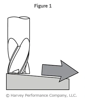
Every machining operation entails a radial and axial depth of cut strategy. Radial depth of cut (RDOC), the distance a tool is stepping over into a workpiece; and Axial depth of cut (ADOC), the distance a tool engages a workpiece along its centerline, are the backbones of machining. Machining to appropriate depths – whether slotting or peripheral milling (profiling, roughing, and finishing), is vital to your machining success (Figure 1).
Below, you will be introduced to the traditional methods for both peripheral milling and slotting. Additionally, High Efficiency Milling (HEM) strategies – and appropriate cutting depths for this method – will be explained.

Quick Definitions:
Radial Depth of Cut (RDOC): The distance a tool is stepping over into a workpiece. Also referred to as Stepover, Cut Width, or XY.
Axial Depth of Cut (ADOC): The distance a tool engages a workpiece along its centerline. Also referred to as Stepdown, or Cut Depth.
Peripheral Milling: An application in which only a percentage of the tool’s cutter diameter is engaging a part.
Slotting: An application in which the tool’s entire cutter diameter is engaging a part.
High Efficiency Milling (HEM): A newer machining strategy in which a light RDOC and heavy ADOC is paired with increased feed rates to achieve higher material removal rates and decreased tool wear.

Peripheral Milling Styles and Appropriate RDOC
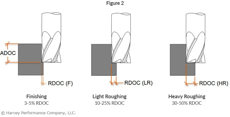
The amount a tool engages a workpiece radially during peripheral milling is dependent upon the operation being performed (Figure 2). In finishing applications, smaller amounts of material are removed from a wall, equating to about 3-5% of the cutter diameter per radial pass. In heavy roughing applications, 30-50% of the tool’s cutter diameter is engaged with the part. Although heavy roughing involves a higher RDOC than finishing, the ADOC is most often smaller than for finishing due to load on the tool.
Slotting Styles and Appropriate ADOC Engagement
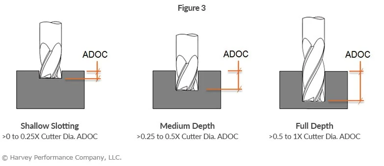
The amount a tool engages a part axially during a slotting operation must be appropriate for the tool being used (Figure 3). Using an inappropriate approach could lead to tool deflection and damage, and poor part quality.
End mills come in various length of cut options, as well as numerous reached options. Choosing the tool that allows the completion of a project with the least deflection, and highest productivity, is critical. As the ADOC needed to slot can be lower, a stub length of cut is often the strongest and most appropriate tool choice. As slot depths increase, longer lengths of cut become necessary, but reached tooling should be used where allowable.
Depth of Cut Strategy for High Efficiency Milling (HEM)
Pairing a light RDOC and heavy ADOC with high performance toolpaths is a machining strategy known as High Efficiency Milling or HEM. With this machining style, feed rates can be increased and cuts are kept uniform to evenly distribute stresses across the cutting portion of the tool, prolonging tool life.
Traditional Strategy
- Heavy RDOC
- Light ADOC
- Conservative Feed Rate
Newer Strategy – High Efficiency Milling (HEM)
- Light RDOC
- Heavy ADOC
- Increased Feed Rate
Click Here to Access Our Free Educational Webinar on High Efficiency Milling
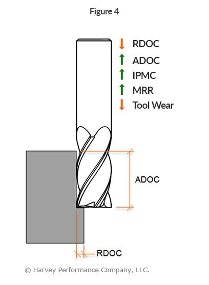
HEM involves using 7-30% of the tool diameter radially and up to twice the cutter diameter axially, paired with increased feed rates (Figure 4). Accounting for chip thinning, this combination of running parameters can result in noticeably higher metal removal rates (MRR). Modern CAM software often offers a complete high performance solution with built-in features for HEM toolpaths. These principals can also be applied to trochoidal toolpaths for slotting applications.
Corner Engagement: How to Machine Corners
Understanding Corner Engagement
During the milling process, and especially during corner engagement, tools undergo significant variations in cutting forces. One common and difficult situation is when a cutting tool experiences an “inside corner” condition. This is where the tool’s engagement angle significantly increases, potentially resulting in poor performance.
Challenges of Corner Engagement
Engaging corners improperly can lead to various issues, affecting both performance and quality. Some common challenges include:
- Chatter: – visible imperfections in corner finishes
- Deflection – detected by unwanted wall taper measurements
- Strange cutting sound – tool squawking or chirping in the corners
- Tool breakage/failure or chipping – resulting from excessive stress or improper handling
Least Effective Approach (Figure 1)
Generating an inside part radius that matches the radius of the tool at a 90° direction range is not a desirable approach to machining a corner. In this approach, the tool experiences extra material to cut (dark gray), an increased engagement angle, and a direction change. As a result, issues including chatter, tool deflection/ breakage, and poor surface finish may occur.
Feed rate may need to be lessened depending on the “tool radius-to-part radius ratio.”

More Effective Approach (Figure 2)
Generating an inside part radius that matches the radius of the tool with a sweeping direction change is a more desirable approach for corner engagement. The smaller radial depths of cut (RDOC) in this example help to manage the angle of engagement, but at the final pass, the tool will still experience a very high engagement angle. Common results of this approach will be chatter, tool deflection/breakage and poor surface finish.
Feed rate may need to be reduced by 30-50% depending on the “tool radius-to-part radius ratio.”

Most Effective Approach For Corner Engagement (Figure 3)
Generating an inside part radius with a smaller tool and a sweeping action creates a much more desirable machining approach. The manageable RDOC and smaller tool diameter allow for management of the tool engagement angle, higher feed rates and better surface finishes. As the cutter reaches full radial depth, its engagement angle will increase, but the feed reduction should be much less than in the previous approaches.
Feed rate may need to be heightened depending on the “tool-to-part ratio.” Utilize tools that are smaller than the corner you are machining.

Corner engagement is a critical aspect of machining that demands attention to detail and strategic planning. By implementing effective techniques and leveraging appropriate tools, manufacturers can overcome challenges associated with corner machining and achieve superior results.
Ramping to Success
Poor tool life and premature tool failure are concerns in every machining application. Something as simple as tool path selection – and how a tool first enters a part – can make all the difference. Tool entry has a great deal of influence on its overall success, as it’s one of the most punishing operations for a cutter. Ramping into a part, via a circular or linear toolpath, is one of the most popular and oftentimes the most successful methods (Figure 1). Below, learn what ramping is, its benefits, and in which situations it can be used.
Check Out Our Micromachining Webinar to Get More Life Out of Your Miniature Cutting Tools
What is Ramping?
Ramping refers to simultaneous radial and axial motion of a cutting tool, making an angular tool path. Oftentimes, this method is used to approach a part when there is a need to create closed forms such as pockets, cavities, engravings, and holes. In doing so, the need to plunge with an end mill or drill to create a starting point is eliminated. Ramping is particularly important in micromachining where even the slightest imbalance in cutting forces can cause tool failure.
There are two types of ramping toolpaths: Linear and Circular (Figure 2 ).
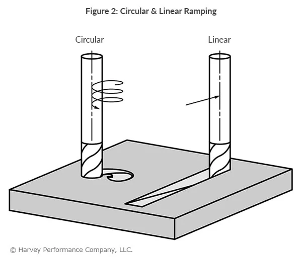
Linear Ramping involves moving a cutting tool along two axes (the z-axis and one of the x, y axes). This method has significant more radial engagement with complementary increased cutting forces distributed across only two axes.
Circular Ramping (Helical Interpolation) has a spiral motion of the cutting tool that engages all three axes (x, y, and z axes). This method typically has less radial engagement on the cutting tool, with the cutting forces distributed across the three different axes. This is the recommended method, as it ensures the longest tool life.
Suggested Starting Ramp Angles:
Soft/Non-Ferrous Materials: 3° – 10°
Hard/Ferrous Materials 1° – 3°
Benefits of Ramping
When a tool enters the part via a Ramping method, it gradually increases in depth, preventing any shock loading on end mills. This reduces costs resulting from unnecessary tool breakage. Ramping produces smaller chips when compared to plunging, which makes chip evacuation faster and easier. As a result, cycle time can be decreased by running the end mill at faster parameters. Ramping also creates an extra space in the tool changer that would otherwise be occupied by a drill purposed with machining a starter hole.

Arcing
Similar to ramping in both method and benefit, arcing is another technique of approaching a workpiece (See Figure 3).
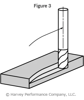
While ramping enters the part from the top, arcing enters from the side. The end mill follows a curved tool path (or arc) when milling, thus gradually increasing the load on the tool as the tool enters the part, as well as gradually decreasing the load as the tool exits the part. In this way, shock loading and possible tool breakage are avoided.
For more information on ramping, arcing, and other tool entry methods, please see Helical Solutions’ “Types of Tool Entry.”
Dodging Dovetail Headaches: 7 Common Dovetail Mistakes
Cutting With Dovetails
While they are specialty tools, dovetail style cutters have a broad range of applications. Dovetails are typically used to cut O-ring grooves in fluid and pressure devices, industrial slides and detailed undercutting work. Dovetail cutters have a trapezoidal shape—like the shape of a dove’s tail. General purpose dovetails are used to undercut or deburr features in a workpiece. O-ring dovetail cutters are held to specific standards to cut a groove that is wider at the bottom than the top. This trapezoidal groove shape is designed to hold the O-ring and keep it from being displaced.
Check our Harvey Tool’s Comprehensive Selection of Dovetail Cutters that Ship to You Today.
Avoiding Tool Failure
The dovetail cutter’s design makes it fragile, finicky, and highly susceptible to failure. In calculating job specifications, machinists frequently treat dovetail cutters as larger than they really are because of their design, leading to unnecessary tool breakage. They mistake the tool’s larger end diameter as the critical dimension when in fact the smaller neck diameter is more important in making machining calculations.
As the tools are downsized for micro-applications, their unique shape requires special considerations. When machinists understand the true size of the tool, however, they can minimize breakage and optimize cycle time.
Miniature Matters – Micro Dovetailing
As the trend towards miniaturization continues, more dovetailing applications arise along with the need for applying the proper technique when dovetailing microscale parts and features. However, there are several common misunderstandings about the proper use of dovetails, which can lead to increased tool breakage and less-than-optimal cycle times.
There are seven common mistakes made when dovetailing and several strategies for avoiding them:
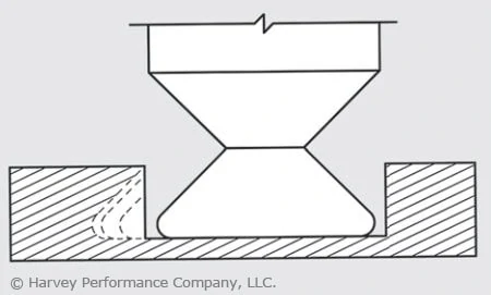
1. Not Taking Advantage of Drop Holes
Many O-ring applications allow for a drop hole to insert the cutter into the groove. Take advantage of a drop hole if the part design allows it, as it will permit usage of the largest, most rigid tool possible, minimizing the chance of breakage (Figure 1).
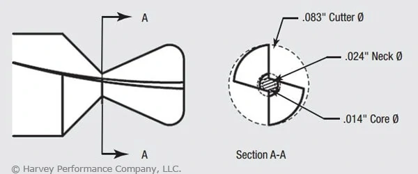
2. Misunderstanding a Dovetail’s True Neck Diameter.
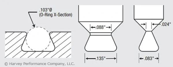
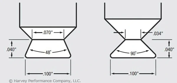
The dovetail’s profile includes a small neck diameter behind a larger end-cutting diameter. In addition, the flute runs through the neck, further reducing the tool’s core diameter. (In the example shown in Figure 2, this factor produces a core diameter of just 0.014″.) The net result is that an otherwise larger tool becomes more of a microtool. The torque generated by the larger diameter is, in effect, multiplied as it moves to the narrower neck diameter. You must remember that excess stress may be placed on the tool, leading to breakage. Furthermore, as the included angle of a dovetail increases, the neck diameter and core diameter are further reduced. O-ring dovetail cutters have an included angle of 48°. Another common included angle for general purpose dovetails is 90°. Figure 3 illustrates how two 0.100″-dia. dovetail tools have different neck diameters of 0.070″ vs. 0.034″ and different included angles of 48° vs. 90°.
3. Calculating Speeds and Feeds from the Wrong Diameter.
Machinists frequently use the wrong tool diameter to calculate feed rates for dovetail cutters, increasing breakage. In micromachining applications where the margin for error is significantly reduced, calculating the feed on the wrong diameter can cause instantaneous tool failure. Due to the angular slope of a dovetail cutter’s profile, the tool has a variable diameter. While the larger end diameter is used for speed calculations, the smaller neck diameter should be used for feed calculations. This yields a smaller chip load per tooth. For example, a 0.083″-dia. tool cutting aluminum might have a chip load of approximately 0.00065 IPT, while a 0.024″-dia. mill cutting the same material might have a 0.0002-ipt chip load. This means the smaller tool has a chip load three times smaller than the larger tool, which requires a significantly different feed calculation.
4. Errors in Considering Depth of Cut.
In micromachining applications, machinists must choose a depth of cut (DOC) that does not exceed the limits of the fragile tool. Typically, a square end mill roughs a slot and the dovetail cutter then removes the remaining triangular-shaped portion. As the dovetail is stepped over with each subsequent radial cut, the cutter’s engagement increases with each pass. A standard end mill allows for multiple passes by varying the axial DOC. However, a dovetail cutter has a fixed axial DOC, which allows changes to be made only to the radial DOC. Therefore, the size of each successive step-over must decrease to maintain a more consistent tool load and avoid tool breakage (Figure 4).
5. Failing to Climb Mill.
Although conventional milling has the benefit of gradually loading the tool, in low-chip load applications (as dictated by a dovetail cutter’s small neck diameter) the tool has a tendency to rub or push the workpiece as it enters the cut, creating chatter, deflection and premature cutting edge failure. The dovetail has a long cutting surface and tooth pressure becomes increasingly critical with each pass. Due to the low chip loads encountered in micromachining, this approach is even more critical to avoid rubbing. Although climb milling loads the tool faster than conventional milling, it allows the tool to cut more freely, providing less deflection, finer finish and longer cutting-edge life. As a result, climb milling is recommended when dovetailing.

6. Improper Chip Flushing.
Because dovetail cuts are typically made in a semi-enclosed profile, it is critical to flush chips from the cavity. In micro-dovetailing applications, chip packing and recutting due to poorly evacuated chips from a semi-enclosed profile will dull the cutter and lead to premature tool failure. In addition to cooling and lubricating, a high-pressure coolant effectively evacuates chips. However, excessive coolant pressure placed directly on the tool can cause tool vibration and deflection and even break a microtool before it touches the workpiece. Take care to provide adequate pressure to remove chips without putting undue pressure on the tool itself. Specific coolant pressure settings will depend upon the size of the groove, the tool size and the workpiece material. Also, a coolant nozzle on either side of the cutter cleans out the groove ahead of and behind the cutter. An air blast or vacuum hose could also effectively remove chips.
7. Giving the Job Away.
As discussed in item number 3, lower chip loads result in significantly lower material-removal rates, which ultimately increase cycle time. In the previous example, the chip load was three times smaller, which would increase cycle time by the same amount. Cycle time must be factored into your quote to ensure a profitable margin on the job. In addition to the important micro-dovetailing considerations discussed here, don’t forget to apply the basics critical to all tools. These include keeping runout low, using tools with application-specific coatings and ensuring setups are rigid. All of these considerations become more important in micro-applications because as tools get smaller, they become increasingly fragile, decreasing the margin of error. Understanding a dovetail cutter’s profile and calculating job specifications accordingly is critical to a successful operation. Doing so will help you reach your ultimate goal: bidding the job properly and optimizing cycle time without unnecessary breakage.
This article was written by Peter P. Jenkins of Harvey Tool Company, and it originally appeared in MicroManufacturing Magazine.
Overcoming Composite Holemaking Challenges
Harvey Tool’s Miniature High Performance Composite Drills are specifically designed with point geometry optimized for the unique properties of composite materials. Our Double Angle style is engineered to overcome common problems in layered composites and our Brad Point style is built to avoid the issues frequently experienced in fibrous composites.
Circular Interpolation: Machining Circular Tool Paths
When machining, proper speeds and feeds are very important to avoid breakage and maximize performance. Traditional end milling formulas use Surface Footage (SFM) and Chip Load (IPT) to calculate Speed (RPM) and Feed (IPM) rates. These formulas dictate the correct machining parameters for use in a linear path in which the end mill’s centerline is travelling in a straight line. Since not all parts are made of flat surfaces, end mills will invariably need to move in a non-linear path. In the case of machining circular tool paths, the path of the end mill’s centerline is circular. Not surprisingly, this is referred to as Circular Interpolation.
Decrease Cycle Times and Increase Shop Efficiency. Download Our HEM Guidebook.
Cutting Circular Tool Paths
All rotating end mills have their own angular velocity at the outside diameter. But when the tool path is circular, there is an additional component that is introduced, resulting in a compound angular velocity. Basically, this means the velocity of the outside diameter is travelling at a substantially different velocity than originally expected. The cause of the compound angular velocity is seen in the disparity between the tool path lengths.
Internal Circular Tool Paths
Figure A shows the cross section of a cutting tool on a linear path, with the teeth having angular velocity due to tool rotation, and the center of the tool having a linear feed. Note that the tool path length will always be equal to the length of the machined edge. Figure B shows the same cutting tool on an internal circular path, as done when machining a hole. In this case, the angular velocity of the teeth is changed as a result of an additional component from the circular path of the tool’s center. The diameter of the tool path is smaller than that of the major diameter being cut. Or, in other words, the tool path length is shorter than the machined edge length, increasing the angular velocity of the teeth. To prevent overfeeding and the possibility of tool breakage, the increased angular velocity of the teeth must be made the same as in the linear case in Figure A. The formula below can be used to properly lower the feed rate for internal machining:
Internal Adjusted Feed = (Major Diameter-Cutter Diameter) / (Major Diameter) × Linear Feed
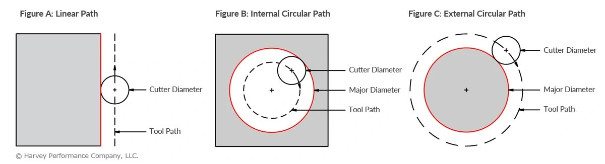
External Circular Tool Paths
Figure C shows the same cutting tool on an external circular path, as done when machining a post. In this case, the diameter of the tool path is larger than the major diameter being cut. This means that the tool path length is longer than the machined edge length, resulting in a decreased angular velocity. To prevent premature dulling and poor tool life due to over-speeding, use the formula below to properly raise the feed rate for external machining. In this way, the decreased angular velocity of the teeth is made the same as in the linear case in Figure A.
External Adjusted Feed = (Major Diameter+Cutter Diameter) / (Major Diameter) × Linear Feed

Optimize Your Performance
By adjusting the feed in the manner provided, internal applications can avoid tool breakage and costly down time. Further, external applications can enjoy optimized performance and shorter cycle times. It should also be noted that this approach can be applied to parts with radiused corners, elliptical features and when helical interpolation is required.
Your Guide to Thin Wall Milling
Milling part features with thin wall characteristics, while also maintaining dimensional accuracy and straightness, can be difficult at best. Although multiple factors contribute, some key components are discussed below and can help to increase your thin wall milling accuracy.
Use Proper Tooling
Necked Tooling
Long length tooling with a long length of cut can spell trouble in thin wall milling situations due to deflection, chatter and breakage. It is essential to keep your tool as strong as possible while maintaining the ability to reach to the desired depth. Necked-down tooling provides added tool strength while also helping you to reach greater than 3x Diameter depths.
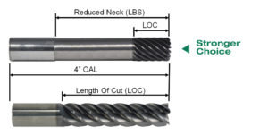
The total extension of an end mill, referred to as length below shank (LBS), represents the dimension that characterizes the necked length of the tool in use. This measurement is taken from the beginning of the necked section to the bottom of the cutting end of the tool. The neck relief serves the purpose of creating room for chip removal and preventing the shank from friction in deep-pocket milling scenarios.
Depth of Cut Selection
Axial Depth of Cut (ADOC)
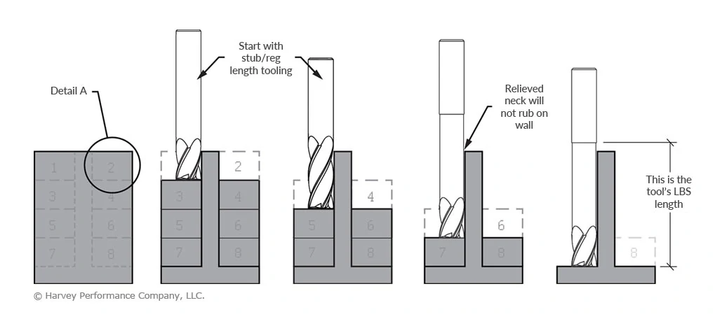
To support the walls during thin wall machining, keep a wide-cross section behind it. We recommend utilizing a “stepped down” approach, which divides the total wall height to manageable depths while working each side of the wall. The Axial Depth of Cut (ADOC) dimension will vary depending on the material (and its hardness) being cut.
Radial Depth of Cut (RDOC)
A progressive Radial Depth Of Cut (RDOC) strategy is also important as the thin wall height is increasing. Reducing tool pressure while support stock is disappearing is equally important to keep the thin wall stable.
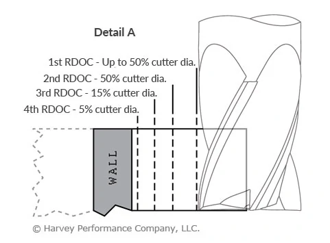
- Detail A represents a 5-step progressive radial approach. The number of passes will depend upon your particular application, material hardness and final wall dimensions.
- This approach helps to keep the pressure off the wall as you make your way towards it. Additionally, it is recommended to alternate sides when using this RDOC strategy.
- The final RDOC passes should be very light to keep wall vibration to a minimum while maximizing your part finish.
Additional Thin Wall Milling Accuracy Tips:
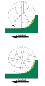
Climb Milling
Climb milling, gaining popularity among machinists seeking efficiency and extended tool life, minimizes heat generation and friction. Chips are ejected behind the cutter, reducing the likelihood of chip recutting. The chip initiates at its widest point and diminishes, leading to the transfer of generated heat into the chip rather than the tool or workpiece. This results in longer tool lifespan, enabling more parts per tool and lessened costs. Additionally, it contributes to a superior part finish by optimizing chip formation at the cutting edge.
Wall Stabilization
Manual vibration dampening and wall stabilization can be achieved by using thermoplastic compounds, or wax, which can be thermally removed.
HEM Toolpaths
The use of HEM toolpaths can optimize tool performance. It is an advanced machining approach which involves combining a low RDOC (Radial Depth of Cut) with a high ADOC (Axial Depth of Cut), along with elevated feed rates. This combination aims to enhance material removal rates and reduce tool wear.
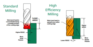
High Efficiency Milling (HEM) varies from conventional milling, where a higher RDOC and lower ADOC are usually recommended. Conventional milling tends to generate concentrated heat in a specific area of the cutting tool, expediting tool wear. Additionally, while conventional milling requires more axial passes, HEM toolpaths involve more radial passes.
How to Tackle Deep Cavity Milling the Right Way
Deep cavity milling is a common yet demanding milling operation. In this style, the tool has a large amount of overhang – or how far a cutting tool is sticking out from its tool holder. The most common challenges of deep cavity milling include tool deflection, chip evacuation, and tool reach.
Avoid Tool Deflection
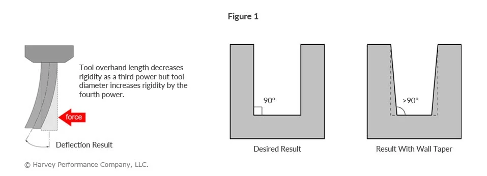
Excess overhang is the leading cause of tool deflection, due to a lack of rigidity. Besides immediate tool breakage and potential part scrapping, excessive overhang can compromise dimensional accuracy and prevent a desirable finish.
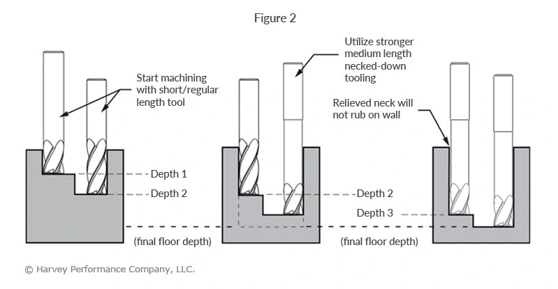
Tool deflection causes wall taper to occur (Figure 1), resulting in unintended dimensions and, most likely, an unusable part. By using the largest possible diameter, necked tooling, and progressively stepping down with lighter Axial Depths Of Cut (ADOC), wall taper is greatly reduced (Figure 2).
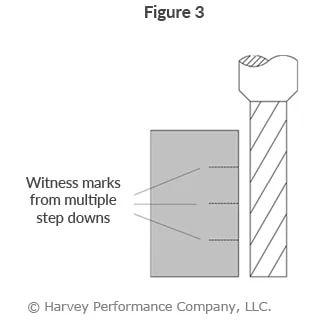
Achieve Optimal Finish
Although increasing your step-downs and decreasing your ADOC are ideal for roughing in deep cavities, this process oftentimes leaves witness marks at each step down. In order to achieve a quality finish, Long Reach, Long Flute Finishing End Mills (coupled with a light Radial Depth of Cut) are required (Figure 3).
Mill to the Required Depth
Avoiding tool deflection and achieving an acceptable finish are challenges that need to be acknowledged, but what if you can’t even reach your required depth? Inability to reach the required depth can be a result of the wrong tool holder or simply a problem of not having access to long enough tooling.
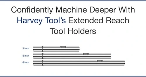
Fortunately, your tool holder’s effective reach can be easily increased with Harvey Tool’s Extended Reach Tool Holder, which allows you to reach up to 6 inches deeper.
Confidently Machine Deeper With Harvey Tool’s Extended Reach Tool Holders
Evacuate Chips Effectively
Many machining operations are challenged by chip evacuation, but none more so than Deep Cavity Milling. With a deep cavity, chips face more obstruction, making it more difficult to evacuate them. This frequently results in greater tool wear from chip cutting and halted production from clogged flute valleys.
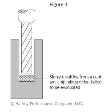
High pressure coolant, especially through the spindle, aids in the chip evacuation process. However, air coolant is a better option if heat and lubricity are not concerns, since coolant-chip mixtures can form a “slurry” at the bottom of deep cavities (Figure 4). When machining hardened alloys, where smaller, powder-like chips are created, slurry’s are a commonality
that must be avoided.