Harvey Performance Company
  • About Us
    • Company Overview
    • Our Unique Strengths
    • Our Partners
    • Our History
    • Our Locations
    • Sustainability
    • Giving Back
      • Giving Back
      • One Tree Planted
    • News
      • News
      • Press
  • Our Brands
    • Harvey Tool
    • Helical Solutions
    • Micro 100
    • Titan USA
    • CoreHog
    • Valor Holemaking
    • ATA Air Tools
    • ATA SGSPRO
    • Garryson
    • ITC
    • Karnasch
    • Van Hoorn Carbide
  • Products
    • Milling
    • Drilling
    • Grinding
    • Micro Tools
    • Sinking
    • Sawing
    • Composite Tools
    • Threading
    • Turning
    • Beveling
    • Reaming
    • Air Tools
  • Solutions
    • Aerospace
    • Automotive
    • Defense
    • Energy
    • Foundries
    • Marine
    • Medical
    • Mold & Die
    • Oil & Gas
    • Power Generation
    • Rail
  • Resources
    • CAM & TDM Tool Libraries
    • Machining Advisor Pro
    • In the Loupe Blog
    • Webinars
  • Careers
  • Contact Us
  • Menu Menu
  • Link to LinkedIn
  • Link to Facebook

Tag Archive for: Machining

Get to Know Machining Advisor Pro

September 13, 2018/2 Comments/in CNC Machining, CNC Programming, Machining 101, Machining Advisor Pro Help, Quick Tips/by David Pichette

Machining Advisor Pro (MAP) is a tool to quickly, seamlessly, and accurately deliver recommended running parameters to machinists using Helical Solutions end mills. This download-free and mobile-friendly application takes into account a user’s machine, tool path, set-up, and material to offer tailored, specific speeds and feed parameters to the tools they are using.

How to Begin With Machining Advisor Pro

This section will provide a detailed breakdown of Machining Advisor Pro, moving along step-by-step throughout the entire process of determining your tailored running parameters.

Register Quickly on Desktop or Mobile

To begin with Machining Advisor Pro, start by accessing its web page on the Harvey Performance Company website, or use the mobile version by downloading the application from the App Store or Google Play.

Whether you are using Machining Advisor Pro from the web or your mobile device, machinists must first create an account. The registration process will only need to be done once before you will be able to log into Machining Advisor Pro on both the mobile and web applications immediately.

machining advisor pro

Simply Activate Your Account

The final step in the registration process is to activate your account. To do this, simply click the activation link in the email that was sent to the email address used when registering. If you do not see the email in your inbox, we recommend checking your spam folders or company email filters. From here, you’re able to begin using MAP.

Using Machining Advisor Pro

A user’s experience will be different depending on whether they’re using the web or mobile application. For instance, after logging in, users on the web application will view a single page that contains the Tool, Material, Operation, Machine, Parameter, and Recommendation sections.
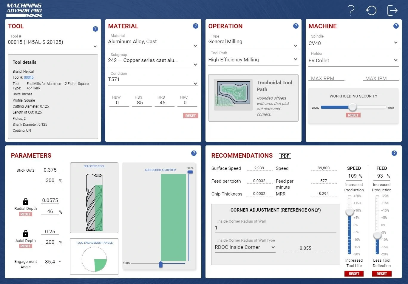
machining advisor pro

On the mobile application, however, the “Input Specs” section is immediately visible. This is a summary of the Tool, Material, Operation, and Machine sections that allow a user to review and access any section. Return to this screen at any point by clicking on the gear icon in the bottom left of the screen.

machining advisor pro

Identify Your Helical Tool

To get started generating your running parameters, specify the Helical Solutions tool that you are using. This can be done by entering the tool number into the “Tool #” input field (highlighted in red below). As you type the tool number, MAP will filter through Helical’s 4,800-plus tools to begin identifying the specific tool you are looking for.

machining advisor pro

Once the tool is selected, the “Tool Details” section will populate the information that is specific to the chosen tool. This information will include the type of tool chosen, its unit of measure, profile, and other key dimensional attributes.

Select the Material You’re Working In

Once your tool information is imported, the material you’re working in will need to be specified. To access this screen on the mobile application, either swipe your screen to the left or click on the “Material” tab seen at the bottom of the screen. You will move from screen to screen across each step in the mobile application by using the same method.

In this section, there are more than 300 specific material grades and conditions available to users. The first dropdown menu will allow you to specify the material you are working in. Then, you can choose the subgroup of that material that is most applicable to your application. In some cases, you will also need to choose a material condition. For example, you can select from “T4” or “T6” condition for 6061 Aluminum.

Machining Advisor Pro provides optimized feeds and speeds that are specific to your application, so it is important that the condition of your material is selected.

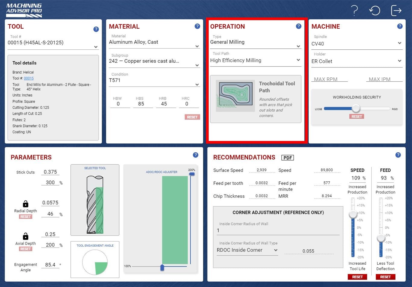
Pick an Operation

The next section of MAP allows the user to define their specific operation. In this section, you will define the tool path strategy that will be used in this application. This can be done by either selecting the tool path from the dropdown menu or clicking on “Tool Path Info” for a visual breakdown and more information on each available toolpath.
Tailor Parameters to Your Machine’s Capabilities

The final section on mobile, and the fourth web section, is the machine section. This is where a user can define the attributes of the machine that you are using. This will include the Max RPM, Max IPM, Spindle, Holder, and work holding security. Running Parameters will adjust based on your responses.
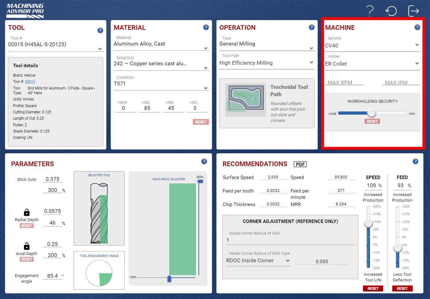
Access Machining Advisor Pro Parameters

Once the Tool, Material, Operation, and Machine sections are populated there will be enough information to generate the initial parameters, speed, and feed. To access these on the mobile app, either swipe left when on the machine tab or tap on the “Output” tab on the bottom menu.
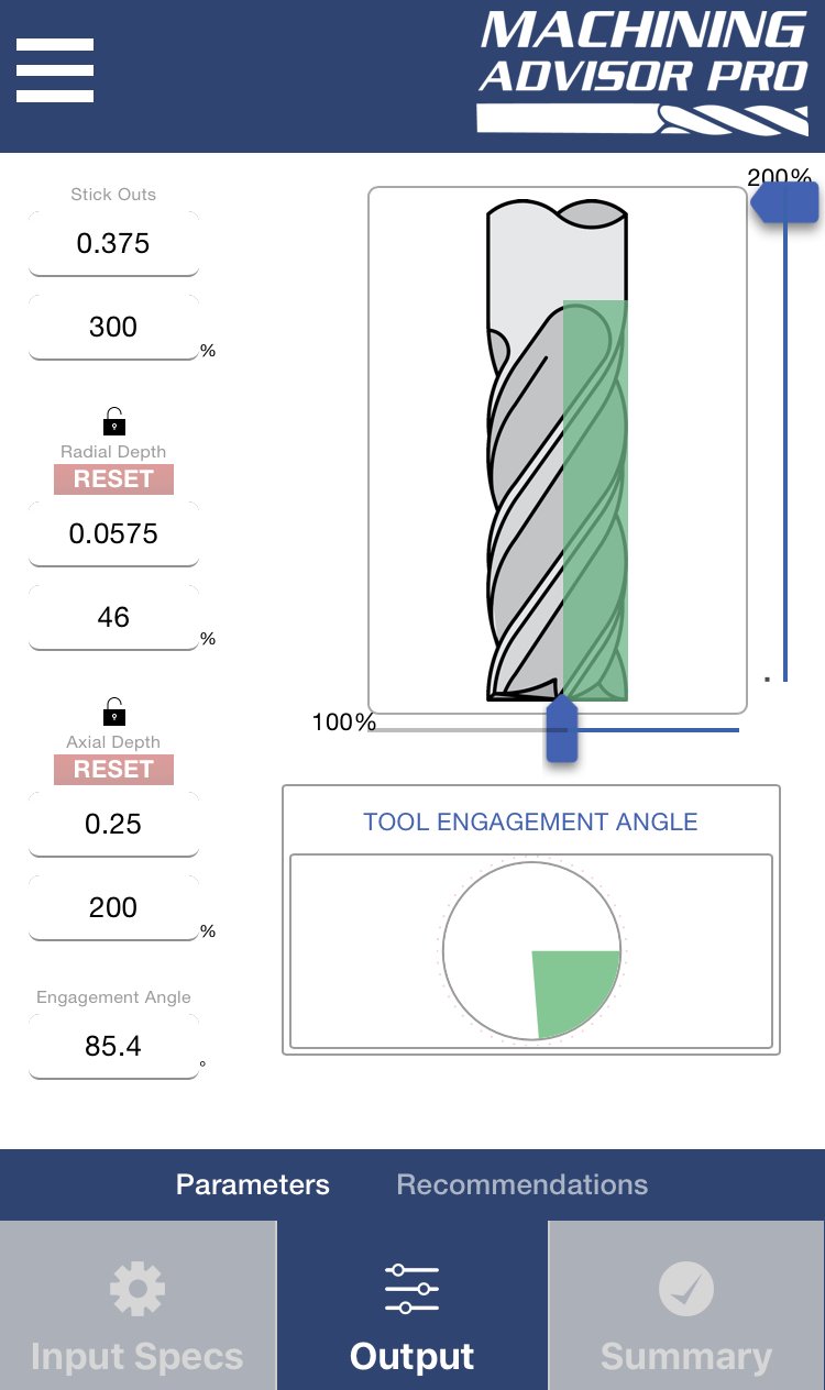
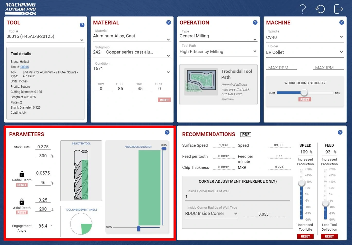
Please note that these are only initial values. Machining Advisor Pro gives you the ability to alter the stick out, axial depth of cut, and radial depth of cut to match the specific application. These changes can either be made by entering the exact numeric value, the % of cutter diameter, or by altering the slider bars. You are now able to lock RDOC or ADOC while adjusting the other depth of cut, allowing for more customization when developing parameters.
machining advisor pro

The parameters section also offers a visual representation of the portion of the tool that will be engaged with the materials as well as the Tool Engagement Angle.

MAP’s Recommendations

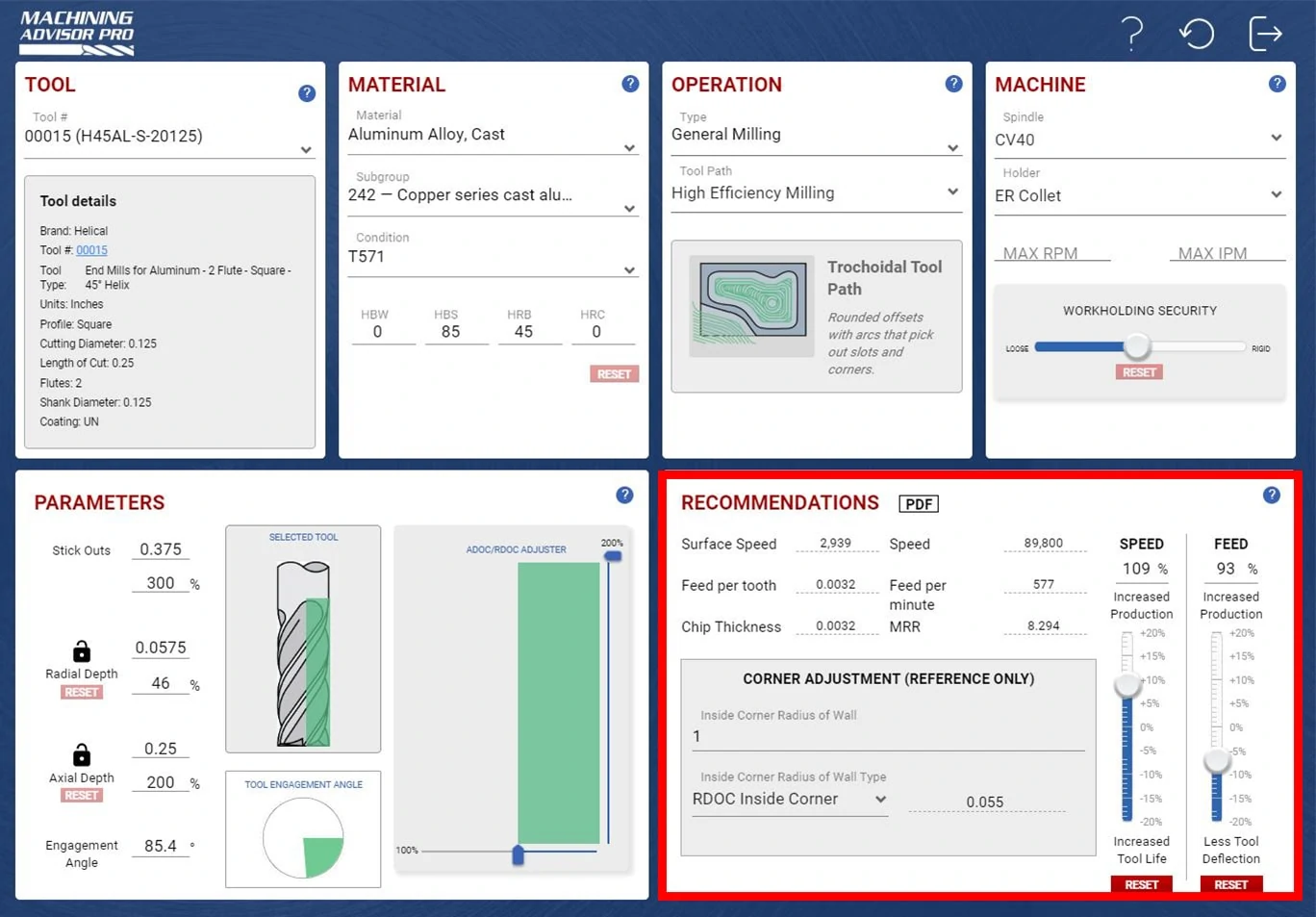
At this point, you can now review the recommended feeds and speeds that Machining Advisor Pro suggests based on the information you have input. These optimized running parameters can then be further refined by altering the speed and feed percentages.
machining advisor pro recommendation

Machining Advisor Pro recommendations can be saved by clicking on the PDF button that is found in the recommendation section on both the web and mobile platforms. This will automatically generate a PDF of the recommendations, allowing you to print, email, or share with others.

Machining Advisor Pro Summarized

The final section, exclusive to the mobile application, is the “Summary” section. To access this section, first tap on the checkmark icon in the bottom menu. This will open a section that is similar to the “Input Specs” section, which will give you a summary of the total parameter outputs. If anything needs to change, you can easily jump to each output item by tapping on the section you need to adjust.

machining advisor pro mobile

This is also where you would go to reset the application to clear all of the inputs and start a new setup. On the web version, this button is found in the upper right-hand corner and looks like a “refresh” icon on a web browser.

Contact Us

For the mobile application, we have implemented an in-app messaging service. This was done to give the user a tool to easily communicate any question they have about the application from within the app. It allows the user to not only send messages, but to also include screenshots of what they are seeing! This can be accessed by clicking on the “Contact Us” option in the same hamburger menu that the Logout and Help & Tips are found.

Click this link to sign up today!

https://www.harveyperformance.com/wp-content/uploads/2018/09/machiningadvisorpro.jpg 600 1599 David Pichette http://www.harveyperformance.com/wp-content/uploads/2018/08/Logo_HarveyPerformanceCompany-4.png David Pichette2018-09-13 14:20:202024-02-09 10:27:36Get to Know Machining Advisor Pro

B&R Custom Machining- Featured Customer

August 23, 2018/0 Comments/in Featured Customer/by Harvey Performance Company

Featured Image Courtesy of B&R Custom Machining

B&R Custom Machining is a rapidly expanding aerospace machine shop located in Ontario, Canada, focused primarily on aerospace and military/defense manufacturing. Over the past 17 years, B&R has grown from a 5 person shop with a few manual mills and lathes, into one of Canada’s most highly respected manufacturing facilities, with nearly 40 employees and 21 precision CNC machines.

B&R focuses on quality assurance and constant improvement, mastering the intimacies of metal cutting and maintaining the highest levels of quality through their unique shop management philosophies. They seek to consistently execute on clear contracts through accurate delivery, competitive price, and high quality machined components.

We talked with Brad Jantzi, Co-Founder and Technical Manager of B&R Custom Machining, to learn about how he started in the industry, his experience with High Efficiency Milling, what he looks for most in a cutting tool, and more!

B&R Custom machining

Photo Courtesy of: B&R Custom Machining

Can you tell us a little bit about how B&R Custom Machining started, and a little background about yourself and the company?

My brother (Ryan Jantzi, CEO/Co-Founder) and I started working in manufacturing back in 2001, when we were just 20/21 years old. We had 5 employees (including ourselves), a few manual mills and lathes, and we were wrapping our parts in newspaper for shipping. We took over from a preexisting shop and assumed their sales and machines.

We bought our first CNC machine in 2003, and immediately recognized the power of CNC and the opportunities it could open up for us. Now, we have 21 CNC machines, 38 employees, and more requests for work than we can keep up with, which is a good thing for the business. We are constantly expanding our team to elevate the business and take on even more work, and are currently hiring for multiple positions if anyone in Ontario is looking for some challenging and rewarding work!

What kind of CNC machines are you guys working with?

Right now we have a lot of Okuma and Matsuura machines, many of which have 5 axis capabilities, and all of them with high RPM spindles. In fact, our “slowest” machine runs at 15k RPM, with our fastest running at 46k. One of our high production machines is our Matsuura LX160, which has the 46k RPM spindle. We use a ton of Harvey Tool and Helical product on that machine and really get to utilize the RPMs.

B&R Custom Machining

Photo Courtesy of: B&R Custom Machining

What sort of material are you cutting?

We work with Aluminum predominantly, but also with a lot of super alloys like Invar, Kovar, Inconel, Custom 455 Stainless, and lots of Titanium. Some of those super alloys are really tricky stuff to machine. Once we learn about them and study them, we keep a recorded database of information to help us dial in parameters. Our head programmer/part planner keeps track of all that information, and our staff will frequently reference old jobs for new parts.

Sounds like a great system you guys have in place. How did B&R Custom Machining get into aerospace manufacturing?

It is a bit of a funny story actually. Just about 12 years ago we were contacted by someone working at Comdev, which is close to our shop, who was looking to have some parts made. We started a business relationship with him, and made him his parts. He was happy with the work, and so we eventually got involved in his company’s switch division and started to make more and more aerospace parts.

aerospace machining

Photo Courtesy of: B&R Custom Machining

We immediately saw the potential of aerospace manufacturing, and it promoted where we wanted to go with CNC machining, so it was a natural fit. It really was a case of being in the right place at the right time and seizing the moment. If an opportunity comes up and you aren’t ready for it, you miss it. You have to be hungry enough to see an opportunity, and confident enough to grab it, while also being competent enough to handle the request. So, we took advantage of what we were given, and we grew and went from there.

Who are some of the major players who you work with?

We have great relationships with Honeywell, MDA Brampton, and MDA Quebec. We actually worked on parts for a Mars Rover with MDA that was commissioned by the Canadian Space Agency, which was really cool to be a part of.

Working with large companies like that means quality is key. Why is high quality tool performance important to you?

High quality and superior tool performance is huge. Aside from cutting conditions, there are two quick things that cause poor performance on a tool: tool life and consistency of the tool quality. One without the other means nothing. We all can measure tool life pretty readily, and there is a clear advantage that some tools have over others, but inconsistent quality can sneak up on you and cause trouble. If you have a tool manufacturer that is only producing a quality tool even 95% of the time, that might seem ok, but that means that 5% of the time you suffer something wrong on the machine. Many times, you won’t know where that trouble is coming from. This causes you to pause the machine, investigate, source the problem, and then ultimately switch the tool and create a new program. It becomes an ordeal. Sometimes it is not as simple as manually adjusting the feed knob, especially when you need to rely on it as a “proven program” the next time around.

So, say the probability of a shortcoming on a machine is “x” with one brand of tooling, but is half of that with a brand like Harvey Tool. Sure, the Harvey Tool product might be 10-20% higher in upfront cost, but that pales in comparison to buying cheaper tools and losing time and money due to machine downtime caused by tool failure. The shop rate for an average machine is right around $100/hour, so machine downtime is much more expensive than the added cost of a quality tool.

B&R Custom machining

Photo Courtesy of: B&R Custom Machining

Inconsistent tool quality can be extremely dangerous to play around with, even outside of machine downtime. We create based on a specific tool and a certain level of expected performance. If that tool cannot be consistent, we now jeopardize an expensive part. The machine never went down, but the part is no good because we programmed based on consistency in tool quality. Again, the cost of scrapped parts heavily outweighs the upfront cost of quality tooling. Tooling is a low cost of what we do here, but poor tooling can cost us thousands versus a few dollars more for quality tools. Too many people focus on the upfront cost, and don’t look downstream through the rest of the process to see how poor quality tooling can affect your business in a much bigger way. We get to see the whole picture because I am involved from cradle to grave, gaining feedback and knowledge along the way.

That’s great feedback Brad, and I think it is important for people to understand what you have laid out here. Speaking of tool performance, have you guys been using High Efficiency Milling techniques in the shop?

Absolutely. We feel that we are on the front edge of efficient milling. We are quite capable of all the latest techniques, as our programmers are well-versed and up to date. For our larger production work, we have programs dialed in that allow us to push the tools to their limits and significantly cut down our cycle times.

What advice would you have for others who are interested in High Efficiency Milling?

Make sure you are smart about using HEM. If we have one-off parts, particularly expensive ones, that do not have time restraints, we want to make sure we have a safe toolpath that will get us the result we want (in terms of quality and cutting security), rather than pushing the thresholds and taking extra time to program the HEM toolpaths. HEM makes total sense for large production runs, but make sure you know when to, and when not to use these techniques to get the most out of HEM.

B&R Custom machining

Photo Courtesy of: B&R Custom Machining

Have you been using Machining Advisor Pro in your shop when you run Helical end mills?

We have been, and it makes for a great point of reference for the Helical end mills. It has become a part of our new employee training, teaching them about speeds and feeds, how hard they can push the Helical tools, and where the safe zones are. Our more experienced guys also frequent it for new situations where they have no data. Machining Advisor Pro helps to verify what we thought we knew, or helps us get the confidence to start planning for a new job.

If you could give one piece of advice to a new machinist, or someone looking to take the #PlungeIntoMachining for the first time, what would it be?

Learn the intimacies of metal cutting. Get ultra-familiar with the results of what is actually happening with your tool, your setup, your part, and your machine. As well, don’t be limited to thinking “it sounds good,” or “it’s going good so far, so that must be acceptable.” In order to push the tools and confirm they are performing well and making money, you need to identify and understand where the threshold of failure is, and back off the right amount. This doesn’t end here though. Cutting conditions change as the tools, holders, machines, and parts change. Learning the nuances of this fluctuating environment and adapting accordingly is essential. Verify your dimensions, mitigate against risk, and control the variables.

Also, get intimate with what causes tools to succeed and fail, and keep a log of it for reference. Develop a passion for cutting; don’t just punch in and punch out each shift. Here at B&R, we are looking for continuous improvement, and employees who can add value. Don’t stand around all day with your arms folded, but keep constant logs of what’s going on and always be learning and thinking of how to understand what is happening, and improve on it. That is what makes a great machinist, and a successful shop.

B&R custom machining

Photo Courtesy of: B&R Custom Machining

https://www.harveyperformance.com/wp-content/uploads/2018/08/Featured-Image-BR-Customer-Machining-IMG.jpg 525 1400 Harvey Performance Company http://www.harveyperformance.com/wp-content/uploads/2018/08/Logo_HarveyPerformanceCompany-4.png Harvey Performance Company2018-08-23 09:30:262021-08-20 14:02:02B&R Custom Machining- Featured Customer

Best Practices of Tolerance Stacking

August 10, 2018/10 Comments/in CNC Machining, High Efficiency Milling, How-To's, Machining 101, Machining Techniques/by Robert Keever

Tolerance stacking, also known as tolerance stack-up, is a critical step in manufacturing that determines how individual part tolerances combine to affect overall accuracy. In precision machining, this analysis is crucial for ensuring tools maintain their functional requirements in the cut while still remaining cost-effective to produce. In essence, tolerances are combined or “stacked-up” as a cumulative equation in machining to ensure feasibility.

Understanding tolerance stacking is crucial for three key reasons: preventing manufacturing failures, optimizing production costs, and ensuring consistent quality across high-volume production runs. This post provides comprehensive analysis methods, practical examples, and best practices for managing tolerances.

After a tolerance is identified on the dimension of a part, it is important to test whether that tolerance would work with the chosen tool’s tolerances: either the upper end or lower end. These tool tolerances are often called out within tool dimension charts. An example can be seen on a Harvey Tool Miniature Square End Mill where the tolerance of +.00005″ and -.0005″ is shown at the Cutter Diameter dimension.

Chart of end mill cutter diameter with tolerance callouts

A part or assembly can be subject to inaccuracies when its tolerances are stacked up incorrectly. Therefore, proper manufacturing tolerance calculation is paramount in winning at the spindle. Starting with a tolerance stack-up analysis prior to machining ensures parts are achievable with current setups, reducing scrapped parts. Continue reading to explore the importance of proper tolerance stacking, common pitfalls, and equations to ensure success.

Why Tolerance Analysis Matters in Manufacturing

Tolerances directly influence the cost and performance of a product. The tighter the tolerance, the more precise a finished part becomes. Tighter tolerances also make a machined part more difficult to manufacture and therefore often more expensive. With this in mind, it is important to find a balance between manufacturability of the part, its functionality, and its cost.

Tips for Successful Tolerance Stacking

Avoid Using Tolerances That are Unnecessarily Small

As stated above, tighter tolerances lead to a higher manufacturing cost as the part is more difficult to make. This higher cost is often due to the increased amount of scrapped parts that can occur when dimensions are found to be out of tolerance. The cost of high quality tool holders and tooling with tighter tolerances can also be an added expense.

Additionally, unnecessarily small tolerances will lead to longer manufacturing times, as more work goes in to ensure that the part meets strict criteria during machining, and after machining in the inspection process.

Be Careful Not to Over Dimension a Part

When an upper and lower tolerance is labeled on every feature of a part, over-dimensioning can become a problem.

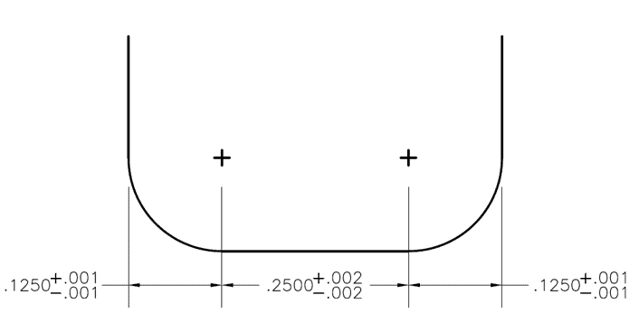
For example, a corner radius end mill with a right and left corner radii might have a tolerance of +/- .001”, and the flat between them has a .002” tolerance. In this case, the tolerance window for the cutter diameter would be +/- .004”, but is oftentimes miscalculated during part dimensioning. Further, placing a tolerance on this callout would cause it to be over dimensioned, and thus the reference dimension “REF” must be left to take the tolerance’s place.

close up of a shaped of slot from a corner radius end mill and its tolerances
Figure 1: Shape of slot created by a corner radius end mill

Utilize Statistical Tolerance Analysis:

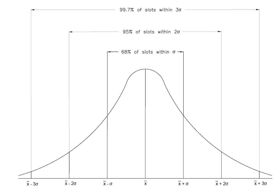
Statistical analysis looks at the likelihood that all three tolerances would be below or above the dimensioned slot width, based on a standard deviation. This probability is represented by a normal probability density function, which can be seen in figure 2 below. By combining all the probabilities of the different parts and dimensions in a design, we can determine the probability that a part will have a problem, or fail altogether, based on the dimensions and tolerance of the parts. Generally this method of analysis is only used for assemblies with four or more tolerances.

stacking tolerances
                                                               Figure 2: Tolerance Stacking: Normal distribution

Before starting a statistical tolerance analysis, you must calculate or choose a tolerance distribution factor. The standard distribution is 3 . This means that most of the data (or in this case tolerances) will be within 3 standard deviations of the mean. The standard deviations of all the tolerances must be divided by this tolerance distribution factor to normalize them from a distribution of 3  to a distribution of 1 . Once this has been done, the root sum squared can be taken to find the standard deviation of the assembly.

Think of it like a cup of coffee being made with 3 different sized beans. In order to make a delicious cup of joe, you must first grind down all of the beans to the same size so they can be added to the coffee filter. In this case, the beans are the standard deviations, the grinder is the tolerance distribution factor, and the coffee filter is the root sum squared equation. This is necessary because some tolerances may have different distribution factors based on the tightness of the tolerance range.

The statistical analysis method is used if there is a requirement that the slot must be .500” wide with a +/- .003” tolerance, but there is no need for the radii (.125”) and the flat (.250”) to be exact as long as they fit within the slot. In this example, we have 3 bilateral tolerances with their standard deviations already available. Since they are bilateral, the standard deviation from the mean would simply be whatever the + or – tolerance value is. For the outside radii, this would be .001” and for the middle flat region this would be .002”.

For this example, let’s find the standard deviation (σ) of each section using equation 1. In this equation represents the standard deviation.

standard deviation

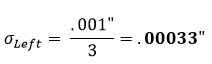
The standard assumption is that a part tolerance represents a +/- 3  normal distribution. Therefore, the distribution factor will be 3. Using equation 1 on the left section of figure 1, we find that its corrected standard deviation equates to:

tolerance stacking

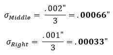
This is then repeated for the middle and right sections:

standard deviation

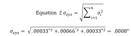
After arriving at these standard deviations, we input the results into equation 2 to find the standard deviation of the tolerance zone. Equation 2 is known as the root sum squared equation.

root sum squared equation for tolerance stack up analysis

At this point, it means that 68% of the slots will be within a +/- .0008” tolerance. Multiplying this tolerance by 2 will result in a 95% confidence window, where multiplying it by 3 will result in a 99% confidence window.

68% of the slots will be within +/- .0008”

95% of the slots will be within +/- .0016”

99% of the slots will be within +/- .0024”

These confidence windows are standard for a normal distributed set of data points. A standard normal distribution can be seen in Figure 2 above.

Statistical tolerance analysis should only be used for assemblies with greater than 4 toleranced parts. A lot of factors were unaccounted for in this simple analysis. This example was for 3 bilateral dimensions whose tolerances were representative of their standard deviations from their means. In standard statistical tolerance analysis, other variables come into play such as angles, runout, and parallelism, which require correction factors.

Did You Know that Harvey Performance Company Brands Partner With the Industry’s Premier Cam Software Providers to Deliver Tooling Libraries?

Click Here to Learn More

Use Worst Case Analysis:

Worst case analysis is the practice of adding up all the tolerances of a part to find the total part tolerance. When performing this type of analysis, each tolerance is set to its largest or smallest limit in its respective range. This total tolerance can then be compared to the performance limits of the part to make sure the assembly is designed properly. This is typically used for only 1 dimension (Only 1 plane, therefore no angles involved) and for assemblies with a small number of parts.

Worst case analysis can also be used when choosing the appropriate cutting tool for your job, as the tool’s tolerance can be added to the parts tolerance for a worst case scenario. Once this scenario is identified, the machinist or engineer can make the appropriate adjustments to keep the part within the dimensions specified on the print.

It should be noted that the worst case scenario rarely ever occurs in actual production. While these analyses can be expensive for manufacturing, it provides peace of mind to machinists by guaranteeing that all assemblies will function properly. Often this method requires tight tolerances because the total stack up at maximum conditions is the primary feature used in design. Tighter tolerances intensify manufacturing costs due to the increased amount of scrapping, production time for inspection, and cost of tooling used on these parts.

Example of worst case scenario in context to Figure 1:

Find the lower specification limit.

For the left corner radius

.125” – .001” = .124”

For the flat section

.250” – .002” = .248”

For the right corner radius

.125” – .001” = .124”

Add all of these together to the lower specification limit:

.124” + .248” + .124” = .496”

Find the upper specification limit:

For the left corner radius

.125” + .001” = .126”

For the flat section

.250” + .002” = .252”

For the right corner radius

.125” + .001” = .126”

Add all of these together to the lower specification limit:

.126” + .252” + .126” = .504”

Subtract the two and divide this answer by two to get the worst case tolerance:

(Upper Limit – Lower Limit)/2 = .004”

Therefore the worst case scenario of this slot is .500” +/- .004”.

https://www.harveyperformance.com/wp-content/uploads/2018/08/Featured-Image-Tolerance-Stacking-IMG.jpg 525 1400 Robert Keever http://www.harveyperformance.com/wp-content/uploads/2018/08/Logo_HarveyPerformanceCompany-4.png Robert Keever2018-08-10 08:35:112024-10-28 16:20:05Best Practices of Tolerance Stacking

Helical Solutions: Behind the Scenes

June 12, 2018/0 Comments/in CNC Machining, CNC Machining Videos, Tools In Action/by Harvey Performance Company

We have shown our end users bits and pieces of our manufacturing process on our website and via social media, but for the first time we decided to open our own doors to the public and show you every step behind how we manufacture and fulfill the Helical Solutions product. We partnered with John Saunders from NYC CNC to create a “Factory Tour” video, covering topics like our CNC grinding machines and setups, tool manufacturing, and our warehouse organization and fulfillment procedures.

In the video below, we first toured our Gorham, Maine manufacturing plan with Plant Manager Adam Martin. Then, we ran a few tests with the Helical tools on our Haas machine, before heading back to our warehouse in Massachusetts to talk about fulfillment and new products with Fulfillment Manager Megan Townsley.

7 Facts Revealed in Our Factory Tour (Plus 3 More That Didn’t Make the Cut)

We know you’re busy making amazing parts, and might not have time for the entire video. To save you time, here are some of the most important facts you should know about Helical.

We Take Quality Control Seriously

Our high performance end mills go through an extensive inspection and quality assurance process before they end up in your machine, with multiple inspection points along the manufacturing journey. At the 17 minute mark of the video, you can learn more about how we monitor the quality of the tools in batches as they are manufactured. If you skip ahead to the 29 minute mark, you can see some of our more advanced inspection machines in action.

We Stand Behind Our Tools with Our Renewal Services

Our Tool Renewal service is a great way to maximize your cost-savings and avoid having to re-purchase new tools without sacrificing any aspects of the original design. At Helical, we do not re-sharpen tools. Rather, we restore your tools to their original geometry. We will review the condition of your used tools and return the cutting edge to its original sharpness and strength, allowing the tool to retain its outstanding performance. The renewed tools go through the same rigorous inspection, edge prep, and coating process that we follow for all our of our new tools. To learn more about our Tool Renewal services, head to the 23:30 mark in the video.

Our Tool Coating Is Done In-House

We have multiple tool coating machines in-house which allow us to take the ground tools right off the line and transfer them to our coating room to have Aplus, Zplus, or Tplus coatings added. These machines also have the capability to create roughly 20 different coatings, which are reserved for specials and custom orders. If you want a close-up look at the coating room and learn how the PVD coating process actually works, head to the 35 minute mark.

Our Standard Catalog Items Are Stocked and Ready for Your Machine

We don’t make our standard catalog tools to order. All of our standard tools are stocked and ready to make some chips in your machine. We also introduce hundreds of new tools to our annual catalog to keep providing our customers with the latest in high performance tooling technology. You can check out our new tools for 2018, including our new High Balance Tools and Metric Tooling, by heading to 52:20, or take quick look at our rows of stocked tools in our warehouse by jumping to 56:55.

Diamond Wheels Grind Carbide Tools

Diamond grinding wheels are the essential tool (outside of the machine) when it comes to grinding carbide. We have a unique management system for our diamond wheels, and a redressing process which can see these wheels last up to a year or more before they need replacement. Adam goes through our “frozen wheel” room with John at the 32:45 mark in the video above.

We Track Every Batch of Tools With Laser Etching

Our tools are all laser etched on-site with our logo, phone number, and tool description, but also with a specific batch number. These batch numbers allow us full track-ability of every tool so we can quickly asses any questions or concerns a customer may have about a tool. With these numbers, we are able to track the tool’s journey all the way back to which machine it was made on, which grinding wheel was used, and who ran the program. We have a couple of these laser etching machines in Maine, which you can see in action at the 42 minute mark.

If You Can Dream It, We Have Probably Made It

We have had some crazy tool drawings come in to our custom tool program over the years, including oddly shaped form tools, tools with a crazy long length of cut, “paper cutters”, and more. You can see some cool examples of custom tools we have manufactured by jumping to the 20 minute mark. If you are more interested in how we actually make them, head to the 27 minute mark to see one of our large custom tools being ground on our Walter machines.

Our Technical Resources Are Second To None

We don’t leave you hanging after your purchase of Helical tools. We have a multitude of technical resources and How-Tos available here on our blog, and we also offer the HEM Guidebook, a complete guide to High Efficiency Milling techniques.

If you are looking for information on speeds and feeds, we suggest you try our Machining Advisor Pro application. This application is designed to increase metal removal rates and shop productivity by generating customizable running parameters optimized for your Helical Solutions end mills. You can click here to get started with Machining Advisor Pro today.

You Will Always Get a Real Person When You Call Helical

If you have technical questions about an upcoming job, a special application, or tooling selection, you can contact Helical by phone at 866-543-5422. Our technical experts are available over the phone Monday-Friday from 8 AM to 5 PM EST, and you will always get a real person to talk to with no automated systems to navigate through. You can also reach our team by email at [email protected].

Questions about where to buy Helical tools? You can give our team a call, or you can find your local distributor by using the “Find a Distributor” tool on our website. Simply choose your state to see a complete list of authorized distributors in your area.

We’re Hiring!

We have a current list of our open opportunities on our website! Open jobs include CNC Machinist, Quality Control Inspector, and Customer Service Representative.

https://www.harveyperformance.com/wp-content/uploads/2018/06/Helical-Behind-the-Scenes.jpg 435 1155 Harvey Performance Company http://www.harveyperformance.com/wp-content/uploads/2018/08/Logo_HarveyPerformanceCompany-4.png Harvey Performance Company2018-06-12 14:30:112022-10-17 10:18:39Helical Solutions: Behind the Scenes

Shining a Light on Diamond End Mills

May 10, 2018/5 Comments/in CNC Machining, Tool Coatings, Tool Selection/by Robert Keever

Diamond tooling and diamond-coated end mills are a great option when machining highly abrasive materials, as the coating properties help to significantly increase tool life relative to uncoated carbide tools. Diamond tools and diamond-like coated tools are only recommended for non-ferrous applications, including highly abrasive materials ranging from graphite to green ceramics, as they have a tendency to break down in the presence of extreme heat.

Understanding the Properties of Diamond Coatings

To ensure proper diamond tooling selection, it’s critical to understand the unique properties and makeup of the coatings, as there are often several diamond coating variations to choose from. Harvey Tool, for example, stocks Amorphous Diamond, CVD Diamond, and PCD Diamond End Mills for customers looking to achieve significantly greater tool life when working in non-ferrous applications.

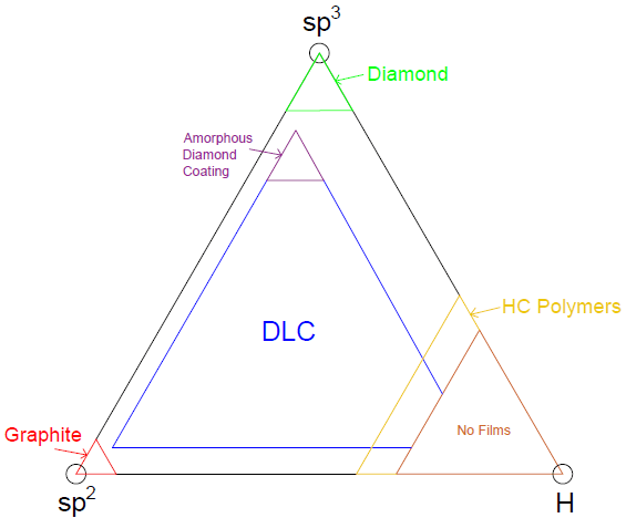
Diamond, the hardest known material on earth, obtains its strength from the structure of carbon molecules. Graphite, a relatively brittle material, can have the same chemical formula as diamond, but is a completely different material; while Graphite has a sp2 bonded hexagonal structure, diamond has a sp3 bonded cubic structure. The cubic structure is harder than the hexagonal structure as more single bonds can be formed to interweave the carbon into a stronger network of molecules.

diamond tool coatings

Amorphous Diamond Coating

Amorphous Diamond is transferred onto carbide tools through a process called physical vapor deposition (PVD). This process spreads a mono-layer of DLC coating about 0.5 – 2.5 microns thick onto any given tool by evaporating a source material and allowing it to condense onto that tool over the course of a few hours.

amorphous diamond coating graphic showcasing thickness added

Chemical Vapor Deposition (CVD)

Chemical Vapor Deposition (CVD) is a coating process used to grow multiple layers of polycrystalline diamond onto carbide tooling. This procedure takes much longer than the standard PVD coating method. During the coating process, hydrogen molecules are dissociated from the carbon molecules deposited onto the tool, leaving a diamond matrix under the right temperature and pressure conditions. Under the wrong conditions, the tool may be simply coated in graphite. 6% cobalt carbide blanks allow for the best adhesion of diamond and a substrate. CVD diamond coated end mills have a typical thickness of coating that is between 8 and 10 microns thick.

CVD Diamond Coating graphic showcasing thickness added by coating

Polycrystalline Diamond (PCD)

Polycrystalline Diamond (PCD) is a synthetic diamond, meaning it is grown in a lab and contains mostly cubic structures. Diamond hardness ranges from about 80 GPa up to about 98 GPa. PCD end mills have the same diamond structure as CVD diamond tools but the binding technique is different. The diamond starts in a powdery form that is sintered onto a carbide plate using cobalt as a solvent metal substrate. This is done at an extreme temperature and pressure as the cobalt infiltrates the powder, causing the grains to grow together. This effectively creates a thick diamond wafer, between 010” and .030” in width, with a carbide base. This carbide base is then brazed onto the head an end mill and sharpened.

PCD Diamond Coating showcasing brazed on cutting edgeHow Diamond Coatings Differ
Coating Hardness & Thickness

Polycrystalline tools (CVD or sintered) have a much higher hardness, thickness, and max working temperature than Amorphous Diamond oated tools. As mentioned previously, a PCD tool consists of a diamond wafer brazed to a carbide body while a CVD tool is a carbide end mill with a relatively thick layer of polycrystalline diamond grown into it. This grown layer causes the CVD tools to have a rounded cutting edge compared to PCD and Amorphous Diamond coated tools. PCD tools have the thickest diamond layer that is ground to a sharp edge for maximum performance and tool life. The difference between PCD tools and CVD coated tools lies in the thickness of this coat and the sharpness of the cutting edge. Amorphous Diamond tools maintain a sharper edge than CVD coated tools because of their thin coating.

Flute Styles

Harvey Tool’s line of PCD end mills are all straight fluted, CVD coated tools are all helically fluted, and Amorphous Diamond tools are offered in a variety of options. The contrast between straight fluted and helically fluted can be seen in the images below, PCD (top) and CVD (bottom). Electrical discharge machining, grinding or erosion are used cut the PCD wafer to the specifications. The size of this wafer limits the range of diameters that can be achieved during manufacturing. In most situations a helically fluted tool would be preferred over a straight fluted tool but with true diamond tooling that is not the case. The materials that PCD tools and CVD coated tools are typically used to cut produce a powdery chip that does not require the same evacuation that a metallic or plastic chip necessitates.

PCD Diamond ball end mill

PCD Ball End Mill

CVD Diamond ball end mill

CVD Ball End Mill

Proper Uses

CVD tools are ideally suited for abrasive material not requiring a sharp cutting edge – typically materials that produce a powdery chip such as composites and graphite. Amorphous Diamond tools have a broad range of non-ferrous applications spanning from carbon fiber to precious metals but ceramics are typically outside their range as they can be too abrasive and wear away the coating. PCD tools overlap their CVD and DLC coated counterparts as they can be used for any non-ferrous abrasive material.

Cut to the Point

Harvey Tool carries physical vapor deposition diamond-like carbon coated tools, chemical vapor deposition diamond tools and polycrystalline diamond tools. PCD tools are composed of the thickest diamond wafer brazed onto a carbide shank and are ground to a sharp edge. CVD coated tools have the diamond grown into a carbide end mill. Amorphous Diamond coated tools have the DLC coated onto them through the PVD process. For more information on the diamond coating best suited for your operation, contact a Harvey Tool Tech Team Member for immediate help.

https://www.harveyperformance.com/wp-content/uploads/2018/05/Feature-Image-Diamond-End-Mills-IMG.jpg 525 1400 Robert Keever http://www.harveyperformance.com/wp-content/uploads/2018/08/Logo_HarveyPerformanceCompany-4.png Robert Keever2018-05-10 10:51:482024-02-12 15:37:16Shining a Light on Diamond End Mills

Tool Deflection & Its Remedies

May 3, 2018/6 Comments/in CNC Machining, How-To's, Machining 101, Troubleshooting Tips/by Jacob Concepcion

What is Tool Deflection?

Every machinist must be aware of tool deflection, as too much deflection can lead to catastrophic failure in the tool or workpiece. Deflection is the displacement of an object under a load causing curvature and/or fracture.

For Example: When looking at a diving board at rest without the pressure of a person’s weight upon it, the board is straight. But as the diver progresses down further to the end of the board, it bends further. Deflection in tooling can be thought of in a similar way.

Signs of Tool Deflection

  • Shortened tool life and/or tool breakage
  • Subpar surface finish
  • Part dimensional inaccuracies

Tool Deflection Remedies

Minimize Overhang

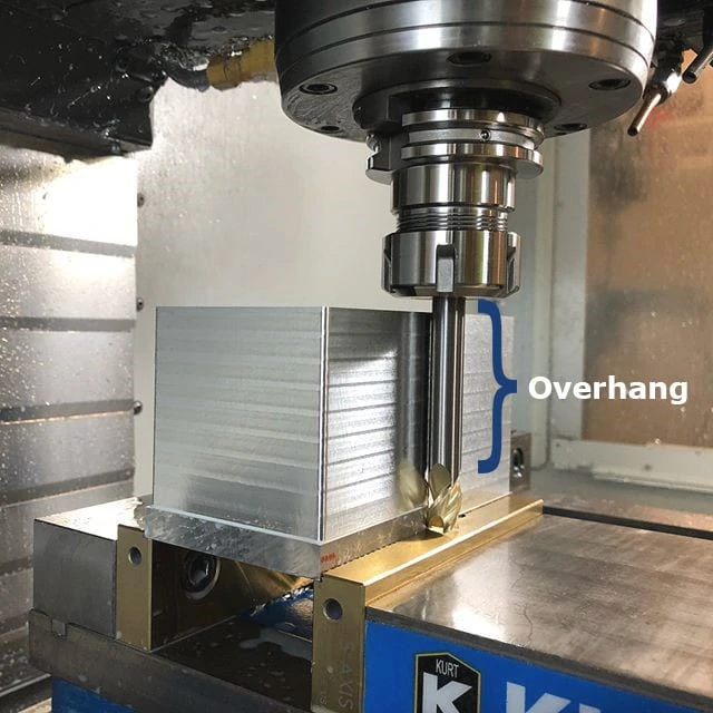
Overhang refers to the distance a tool is sticking out of the tool holder. Simply, as overhang increases, the tool’s likelihood of deflection increases. The larger distance a tool hangs out of the holder, the less shank there is to grip, and depending on the shank length, this could lead to harmonics in the tool that can cause fracture. Simply put, For optimal working conditions, minimize overhang by chucking the tool as much as possible.

extended reach tool in tool holder with overhang depth called out
Image Source: @NuevaPrecision

Long Flute vs. Long Reach

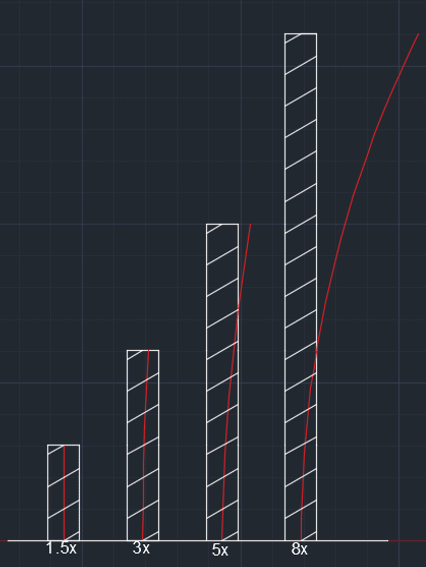
Another way to minimize deflection is having a full grasp on the differences between a long flute and a long reach tool. The reason for such a difference in rigidity between the two is the core diameter of the tool. The more material, the more rigid the tool; the shorter the length of flute, the more rigid the tool and the longer the tool life. While each tooling option has its benefits and necessary uses, using the right option for an operation is important.

The below charts illustrate the relationship between force on the tip and length of flute showing how much the tool will deflect if only the tip is engaged while cutting. One of the key ways to get the longest life out of your tool is by increasing rigidity by selecting the smallest reach and length of cut on the largest diameter tool.

tool deflection in relation to length of tool

tool deflection graph

Click Here to Learn More About Proper Tool Holding and Runout

When to Opt for a Long Reach Tool

Reached tools are typically used to remove material where there is a gap that the shank would not fit in, but a noncutting extension of the cutter diameter would. This length of reach behind the cutting edge is also slightly reduced from the cutter diameter to prevent heeling (rubbing of noncutting surface against the part). Reached tools are one of the best tools to add to a tool crib because of their versatility and tool life.

long reach ball end mill
Long Reach Tool: Variable Helix End Mills for Exotic Alloys – Ball – Long Reach, Stub Flute

When to Opt for a Long Flute Tool

Long Flute tools have longer lengths of cut and are typically used for either maintaining a seamless wall on the side of a part, or within a slot for finishing applications. The core diameter is the same size throughout the cutting length, leading to more potential for deflection within a part. This possibly can lead to a tapered edge if too little of the cutting edge is engaged with a high feed rate. When cutting in deep slots, these tools are very effective. When using HEM, they are also very beneficial due to their chip evacuation capabilities that reached tools do not have.

long flute end milling tool
Long Flute Tool: Miniature End Mills – Square Long Flute

Deflection & Tool Core Strength

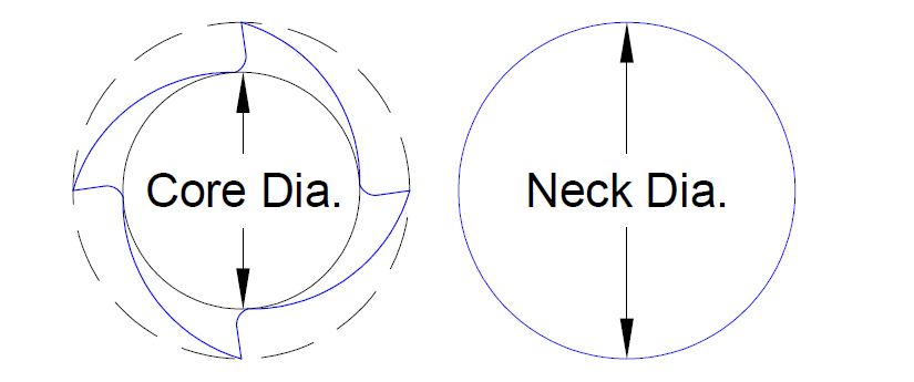
Diameter is an important factor when calculating deflection. Machinists oftentimes use the cutter diameter in the calculation of long flute tools, when in actuality the core diameter (shown below) is the necessary dimension. This is because the fluted portion of a tool has an absence of material in the flute valleys. For a reached tool, the core diameter would be used in the calculation until its reached portion, at which point it transitions to the neck diameter. When changing these values, it can lower deflection to a point where it is not noticeable for the reached tool but could affect critical dimensions in a long flute tool.

core diameter vs neck diameter infographic

Deflection Summarized

Tool deflection can cause damage to your tool and scrap your part if not properly accounted for prior to beginning a job. Be sure to minimize the distance from the tool holder to the tip of the tool to keep deflection to a minimum. For more information on ways to reduce tool deflection in your machining, view Diving into Depth of Cut.

https://www.harveyperformance.com/wp-content/uploads/2018/05/Featured-Image-Tool-Deflection-IMG.jpg 525 1400 Jacob Concepcion http://www.harveyperformance.com/wp-content/uploads/2018/08/Logo_HarveyPerformanceCompany-4.png Jacob Concepcion2018-05-03 09:42:392024-03-05 16:25:18Tool Deflection & Its Remedies

Choosing the Right Pecking Cycle Approach

April 19, 2018/1 Comment/in CNC Machining, Holemaking, How-To's, Machining 101/by Harvey Performance Company

Utilizing a proper pecking cycle strategy when drilling is important to both the life of your tool and its performance in your part. Recommended cycles vary depending on the drill being used, the material you’re machining, and your desired final product.

Start to Boost Your Accuracy with Harvey Tool’s Drilling Guidebook.

What are Pecking Cycles?

Rather than drill to full drill depth in one single plunge, pecking cycles involve several passes – a little at a time. Peck drilling aids the chip evacuation process, helps support tool accuracy while minimizing walking, prevents chip packing and breakage, and results in a better all around final part.

Recommended Pecking Cycles / Steps

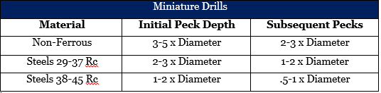
Miniature Drills

miniature drill pecking cycles

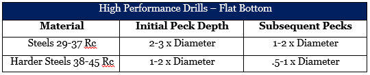
High Performance Drills – Flat Bottom

high performance drill pecking cycles

High Performance Drills – Aluminum & Aluminum Alloys

aluminum pecking cycles

Note: For hole depths 12x or greater, a pilot hole of up to 1.5X Diameter is recommended.

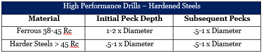
High Performance Drills – Hardened Steels

hardened steels chart
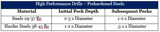
High Performance Drills – Prehardened Steels

prehardened steels chart

Key Pecking Cycle Takeaways

From the above tables, it’s easy to identify how recommended peck drilling cycles change based on the properties of the material being machined. Unsurprisingly, the harder the material is, the shorter the recommended pecking depths are. As always, miniature drills with a diameter of less than .010″ are extremely fragile and require special precautions to avoid immediate failure. For help with your specific job, contact the Harvey Tool Technical Team at 800-645-5609 or [email protected]

https://www.harveyperformance.com/wp-content/uploads/2018/04/Featured-Image-Pecking-Cycle-IMG-1.jpg 525 1400 Harvey Performance Company http://www.harveyperformance.com/wp-content/uploads/2018/08/Logo_HarveyPerformanceCompany-4.png Harvey Performance Company2018-04-19 07:44:542022-01-17 10:16:34Choosing the Right Pecking Cycle Approach

Contouring Considerations

April 2, 2018/0 Comments/in CNC Machining, CNC Programming, Machining Techniques, Tech Tips, Tools In Action/by Jacob Concepcion

What is Contouring?

Contouring a part means creating a fine finish on an irregular or uneven surface. Dissimilar to finishing a flat or even part, cnc contouring involves the finishing of a rounded, curved, or otherwise uniquely shaped part.

CNC Contouring & 5-Axis Machining

5-axis machines are particularly suitable for contouring applications. Because contouring involves the finishing of an intricate or unique part, the multiple axes of movement in play with 5-axis Machining allow for the tool to access tough-to-reach areas, as well as follow intricate tool paths.

Recent  Advances

Advanced CAM software can now write the G-Code (the step-by-step program needed to create a finished part) for a machinists application, which has drastically simplified contouring applications. Simply, rather than spend several hours writing the code for an application, the software now handles this step. Despite these advances, most young machinists are still required to write their own G-Codes early on in their careers to gain valuable familiarity with the machines and their abilities. CAM software, for many, is a luxury earned with time.

Benefits of Advanced CAM Software

Increased Time Savings
Because contouring requires very specific tooling movements and rapidly changing cutting parameters, ridding machinists of the burden of writing their own complex code can save valuable prep time and reduce machining downtime.

Reduced Cycle Times
Generated G-Codes can cut several minutes off of a cycle time by removing redundancies within the application. Rather than contouring an area of the part that does not require it, or has been machined already, the CAM Software locates the very specific areas that require machining time and attention to maximize efficiency.

Improved Consistency
CAM Programs that are packaged with CAD Software such as SolidWorks are typically the best in terms of consistency and ability to handle complex designs. While the CAD Software helps a machinist generate the part, the CAM Program tells a machine how to make it.

Proper Tips

Utilize Proper Cut Depths

Prior to running a contouring operation, an initial roughing cut is taken to remove material in steps on the Z-axis so to leave a limited amount of material for the final contouring pass. In this step, it’s pivotal to leave the right amount of material for contouring — too much material for the contouring pass can result in poor surface finish or a damaged part or tool, while too little material can lead to prolonged cycle time, decreased productivity and a sub par end result.

CNC Contouring planes in multiaxis machining including, x, y and z axii

The contouring application should remove from .010″ to 25% of the tool’s cutter diameter. During contouring, it’s possible for the feeds to decrease while speeds increases, leading to a much smoother finish. It is also important to keep in mind that throughout the finishing cut, the amount of engagement between the tool’s cutting edge and the part will vary regularly – even within a single pass.

Use Best Suited Tooling

Ideal tool selection for contouring operations begins by choosing the proper profile of the tool. A large radius or ball profile is very often used for this operation because it does not leave as much evidence of a tool path. Rather, they effectively smooth the material along the face of the part. Undercutting End Mills, also known as lollipop cutters, have spherical ball profiles that make them excellent choices for contouring applications. Harvey Tool’s 300° Reduced Shank Undercutting End Mill, for example, features a high flute count to benefit part finish for light cut depths, while maintaining the ability to reach tough areas of the front or back side of a part.

cnc contouring undercutting ball end mill

Fact-Check G-Code

While advanced CAM Software will create the G-Code for an application, saving a machinist valuable time and money, accuracy of this code is still vitally important to the overall outcome of the final product. Machinists must look for issues such as wrong tool call out, rapids that come too close to the material, or even offsets that need correcting. Failure to look G-Code over prior to beginning machining can result in catastrophic machine failure and hundreds of thousands of dollars worth of damage.

Inserting an M01 – or a notation to the machine in the G-Code to stop and await machinist approval before moving on to the next step – can help a machinist to ensure that everything is approved with a next phase of an operation, or if any redundancy is set to occur, prior to continuation.

Contouring Summarized

CNC contouring is most often used in 5-axis machines as a finishing operation for uniquely shaped or intricate parts. After an initial roughing pass, the contouring operation – done most often with Undercutting End Mills or Ball End Mills, removes anywhere from .010″ to 25% of the cutter diameter in material from the part to ensure proper part specifications are met and a fine finish is achieved. During contouring, cut only at recommended depths, ensure that G-Code is correct, and use tooling best suited for this operation.

https://www.harveyperformance.com/wp-content/uploads/2018/04/Featured-Image-Contouring-Considerations-IMG.jpg 525 1400 Jacob Concepcion http://www.harveyperformance.com/wp-content/uploads/2018/08/Logo_HarveyPerformanceCompany-4.png Jacob Concepcion2018-04-02 10:09:582024-02-09 10:42:37Contouring Considerations

TL Technologies – Featured Customer

March 12, 2018/0 Comments/in Featured Customer/by Harvey Performance Company

Featured Image Courtesy of TL Technologies

TL Technologies helps manufacturers reduce time to market and drive down per-piece cost with their unique “Intelligent Design and Planning” processes. Located in Lancaster, Pennsylvania, TL Technologies serves manufacturers throughout the mid-Atlantic from their centrally located, 10,000 sq. ft. facility. Their unique manufacturing processes and services quickly made them stand out in the industry since their inception in 2012.

Jonathon Thompson is the Vice President of Engineering at TL Technologies. Jonathon talked with us about their rigorous manufacturing and inspection processes, the advantage of using high-quality tooling, their unique on-site assembly services, and much more in this Featured Customer interview.

Tell us a bit about your shop, how you got started, and what sort of products you manufacture.

TL Technologies got started in January 2012. Our first customers were firearms and defense based. Since then we have diversified our business through growth within customers and word of mouth. We started with the intent to be precise and accurate in a lights-out or nearly automated fashion.

What sort of machines do you use in your shop?

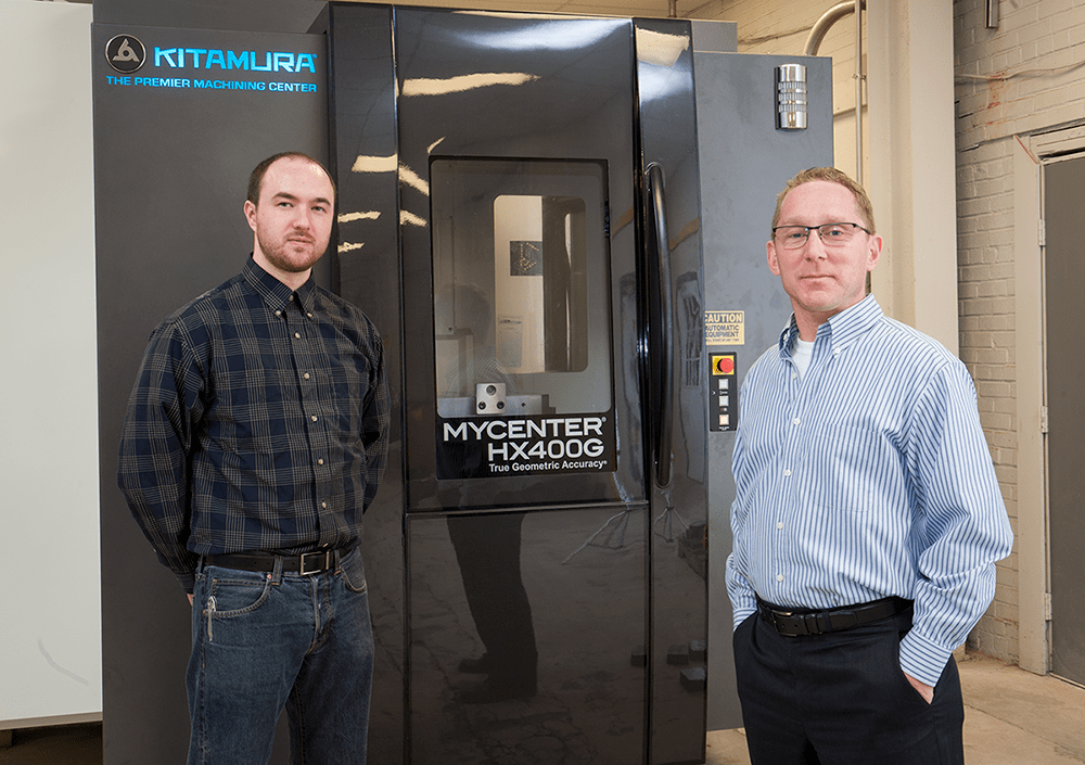
We use an array of modern equipment. 4 axis Kitamura HX400G Horizontal Mills. Nakamura Tome 9 axis Turn Mill, Star 6 axis, and two 5 axis vertical Hurco Machines. All our machines are optioned out with Renishaw probing and all the bells and whistles required to handle high accuracy runs for 24 hours a day with no process issues. Most of the machines have glass scales and thermal packages.

kitamura cnc machine

Photo Courtesy of: TL Technologies

Which materials do you most often work with at your shop?

Mostly steels; the usual 4000 and 8000 series steels. Comparatively less 6061 and 7075 aluminum and other common stainless grades. We’ve been fortunate to have many of our materials within a reasonable range of Rockwell so that we may tool accordingly for most of the business.

How has your experience been with multi-axis machining?

Fantastic. Multi axis Machining has been excellent for us. It requires high-level understanding to fully maximize but the benefits are huge.

On your website, you mention that TL Technologies has never delivered a rejected part. What sets your quality apart from the competition?

From day one and job one, we worked with the customer to understand exactly how they were measuring the parts, exactly with what tools, processes, and methods to identically duplicate the process in our shop. After replicating key processes we performed many correlation studies to ensure that our measurements were within single-digit microns of what our customers were seeing on their end during inspection. This methodology was scaled up into our overall quality program and allows us to greater understand and manufacture our goods. Our ISO process coupled with this method truly does prevent bad work from getting out. We have never had a case where a part did not function or perform due to our oversight or bad specs. There have been failures on the customer side of things due to engineering, bad prints, and tolerance stackups, but we have not supplied parts that were flat out incorrect.

TL Technologies

Photo Courtesy of: TL Technologies

What sort of tolerances do you work in on a daily basis?

Typically single or double-digit microns. .0002” to .003” total is common for a large percentage of specs. It is not unusual for +/-.0002” to run long-term over many fixture stations with no manual adjustment. Our machined products are from 1” to 8” cubed.

What are some of the coolest projects you have had come through the shop?

That’s a good question. TL Technologies sat on the United States Senate committee in 2013 for Small Business and Entrepreneurship. We were featured on the cover of New York Times business section in 2013 as well. Throughout our years we’ve been fortunate to meet many amazing people from high branches in the government, the US Military, top name manufacturers, lenders, and local municipalities. Some of the coolest contacts were folks that formerly operated with US Special Forces. Unfortunately, we cannot comment.

As for projects not covered by an NDA, one of my personal favorites was producing low impact physical therapy products for rehabilitating shoulders after surgery. Though simple in manufacturing, this project provided an array of fun challenges that required high performance tooling, 3D printing, and using our machines with custom cycles. This allowed us to use the equipment very unconventionally. In this way, we were able to provide a cost-effective product utilizing the maximum ability of our equipment with a very short lead-time and low up-front cost.

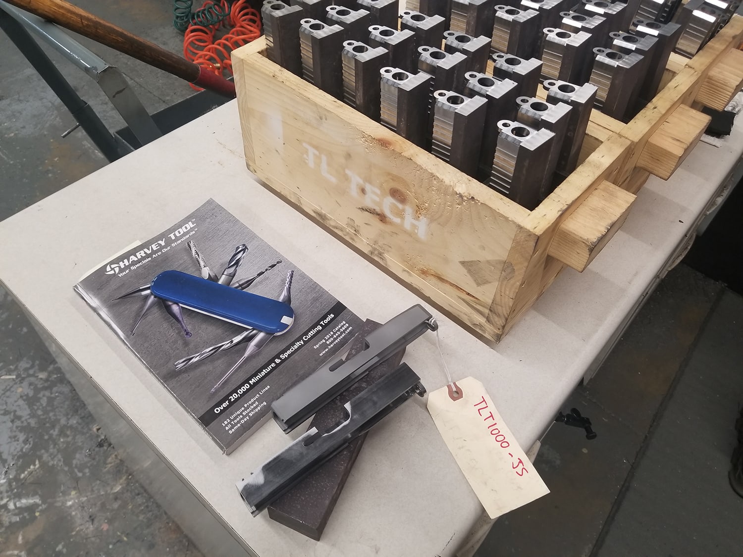
harvey tool catalog

Photo Courtesy of: TL Technologies

You also offer assembly services on-site, which is fairly unique in the industry. Can you talk a little bit more about this?

Sure. Both my business partner and I have tremendous experience with assemblies in both hands-on and directorial roles. Whether it was a high precision multi-axis mechanism that ended up being a custom machine, on and off-road vehicles, or even things like child safety seats, we have had our hands in a lot of things over the years. At TL Technologies we’ve provided assistance to machine tool builders, special tooling designers, consumer goods of various types, and most frequently to firearms builders. Mostly we drive out cost, but as we age we’ve been called upon to troubleshoot high-end assemblies where the issues were not immediately apparent. This led to us creating sub-assemblies and even semi-finished OEM products. This includes hand fitting and assembling collectible pistols and precision bolt action rifles. This is usually offered as a temporary solution or process engineering service to larger companies developing new goods or revamping existing ones, and is offered as part of our comprehensive knowledge to attract clients. It has been very successful.

You service a variety of industries, including defense, automotive, agricultural equipment, and consumer products. Do you have a personal favorite?

I’d have to say the products we make that almost every soldier carries and relies on are my favorite. We take great pride in knowing that these parts have not failed due to machining error since we took over the production years ago on the core components.

TL Technologies

Photo Courtesy of: TL Technologies

Why is American manufacturing important to you?

It’s everything. It’s the heart and soul of all products and by extension facilitates the means with which goods and services exist in our society. By bolstering the skills, knowledge, and experience, we can not only succeed economically but also further the craft and pride of making quality goods. We will always need to be able to make our own goods. The skill and craft to create is more than just economic. We absolutely must embrace and respect the skill and hard work it takes to create. We must pass that knowledge on for posterity so the next generation might find the satisfaction and pride of skilled work.

Why is high-quality tool performance important to you?

It’s everything. The old adage, “Garbage in, garbage out,” is accurate for us. We feel that if we invested so much in these high-end machining centers, it would be criminal to put insufficient tooling and holders into them. We found that by selecting the proper tool with the appropriate sciences behind it we have been able to create products with a cost per cut that is not only competitive, but required to stay current. By keeping the quality as high as possible on the part making side of things, we’ve insured as much ease and reliability into our downstream process as we could. Quality tooling also provides predictability and added safety into the workflow. High-quality carbide tooling is the lifeblood of the business.

Have Harvey Tools had an impact on your performance?

Oh man…frequently. Harvey Tools are a mainstay in our company. If I had to think of some key examples it would have to be your variety of Keyseat Cutters, 3 Flute Counterbores, Extended Reach Ball End Mills, and Miniature End Mills under .040”. The 270 degree Lollipop Cutters are excellent for deburring, and we also rely on the 140° spot drills, corner radius forming tools, and more. In short, not only are the tools good, but they provide exactly what we need and the specifications to handle major OEM jobs. We absolutely love metric and you’ve got that too. Your catalogs help us eliminate the need for customs. That is key to cost and lead time.

harvey tool end mills

Photo Courtesy of: TL Technologies

If you could give one piece of advice to a new machinist ready to take the #PlungeIntoMachining, what would it be?

Embrace the old knowledge and techniques. The manual skills learned with files and hand ground tools translate critically into the concepts you will need to master if CNC becomes your career. Understand how and why materials cut or refuse to cut, what rake angle to use and when, and how to leverage machine physics to help you work smarter instead of harder. Don’t be afraid to jump down the rabbit hole of engineering concepts, materials, physics, elementary chemistry; these all help give you an edge. Machining is done best with comprehensive knowledge of the machines and machining environment. You never stop learning. All that said, keep a fresh perspective. Old knowledge can be great, but operationally each business will likely have its own methods and flow. Try to understand there is more to the overall business picture than you can often see.

Is there anything else you would like to share with the In The Loupe community?

Oh definitely! Buy our stuff!! Ha. We are a supplier of choice for OEM, and small batch bolt actions for rifles, pistol components, and pistol slides. We machine to spec and provide cost-competitive options as well as super-premium options.  We are working now to release our own line of aftermarket products in 2018, so keep an eye out for those!

TL Technologies

Photo Courtesy of: TL Technologies


Would you like to be considered for a future “Featured Customer” blog? Click here to submit your information.

https://www.harveyperformance.com/wp-content/uploads/2018/03/Featured-Image-TL-Technologies-IMG.jpg 525 1400 Harvey Performance Company http://www.harveyperformance.com/wp-content/uploads/2018/08/Logo_HarveyPerformanceCompany-4.png Harvey Performance Company2018-03-12 11:21:312024-02-09 10:52:50TL Technologies – Featured Customer

The Advances of Multiaxis Machining

February 19, 2018/3 Comments/in CNC Machining, CNC Machining Videos, CNC Programming, Machining 101, Machining Techniques, Tools In Action/by Jacob Concepcion

CNC Machine Growth

As the manufacturing industry has developed, so too have the capabilities of machining centers. CNC Machines are constantly being improved and optimized to better handle the requirements of new applications. Perhaps the most important way these machines have improved over time is in the multiple axes of direction they can move, as well as orientation. For instance, a traditional 3-axis machine allows for movement and cutting in three directions, while a 2.5-axis machine can move in three directions but only cut in two. The possible number of axes for a multiaxis machine varies from 4 to 9, depending on the situation. This is assuming that no additional sub-systems are installed to the setup that would provide additional movement. The configuration of a multiaxis machine is dependent on the customer’s operation and the machine manufacturer.

Multiaxis Machining

With this continuous innovation has come the popularity of multiaxis machines – or CNC machines that can perform more than three axes of movement (greater than just the three linear axes X, Y, and Z). Additional axes usually include three rotary axes, as well as movement abilities of the table holding the part or spindle in place. Machines today can move up to 9 axes of direction.

https://www.instagram.com/p/BdssKBsg0Sa/

Multiaxis machines provide several major improvements over CNC machines that only support 3 axes of movement. These benefits include:

  • Increasing part accuracy/consistency by decreasing the number of manual adjustments that need to be made.
  • Reducing the amount of human labor needed as there are fewer manual operations to perform.
  • Improving surface finish as the tool can be moved tangentially across the part surface.
  • Allowing for highly complex parts to be made in a single setup, saving time and cost.

9-Axis Machine Centers

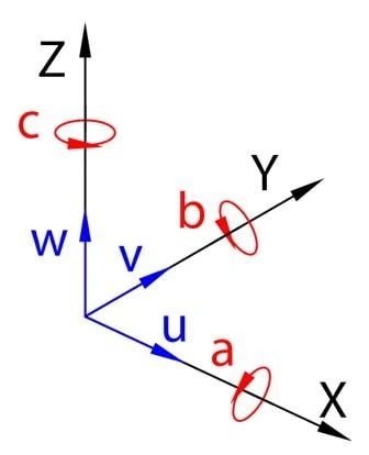
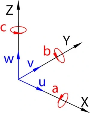
The basic 9-axis naming convention consists of three sets of three axes.

infographic showing x, y and z axii

Set One

The first set is the X, Y, and Z linear axes, where the Z axis is in line with the machine’s spindle, and the X and Y axes are parallel to the surface of the table. This is based on a vertical machining center. For a horizontal machining center, the Z axis would be aligned with the spindle.

Set Two

The second set of axes is the A, B, and C rotary axes, which rotate around the X, Y, and Z axes, respectively. These axes allow for the spindle to be oriented at different angles and in different positions, which enables tools to create more features, thereby decreasing the number of tool changes and maximizing efficiency.

Set Three

The third set of axes is the U, V, and W axes, which are secondary linear axes that are parallel to the X, Y, and Z axes, respectively. While these axes are parallel to the X, Y, and Z axes, they are managed by separate commands. The U axis is common in a lathe machine. This axis allows the cutting tool to move perpendicular to the machine’s spindle, enabling the machined diameter to be adjusted during the machining process.

The Growing Industry of Multiaxis Machining

In summary, as the manufacturing industry has grown, so too have the abilities of CNC Machines. Today, tooling can move across nine different axes, allowing for the machining of more intricate, precise, and delicate parts. Additionally, this development has worked to improve shop efficiency by minimizing manual labor and creating a more perfect final product.

https://www.harveyperformance.com/wp-content/uploads/2018/02/Featured-Image-Multiaxis-Machining-IMG.jpg 525 1400 Jacob Concepcion http://www.harveyperformance.com/wp-content/uploads/2018/08/Logo_HarveyPerformanceCompany-4.png Jacob Concepcion2018-02-19 11:45:102023-10-12 14:31:04The Advances of Multiaxis Machining
Page 7 of 10«‹56789›»
BLOG HOME

Search In the Loupe

More results...

Browse by Topic

How-To’s
Technical Tips
Tools In Action
Featured Customers
Tool Guides

Free Drilling Guidebook

DOWNLOAD

Recent Posts

  • Machining a Complex Part with Harvey Tool
  • Drill Substrate Guide: HSS vs Cobalt vs Carbide
  • The Key Differences Between Helical’s Tool Coatings

Stay In The Loupe!

Sign up to receive a monthly recap of:
– The latest machining solutions
– Machining tips and tricks
– A recap of our most popular posts

SIGN UP

Contact Us


Address
428 Newburyport Turnpike
Rowley, MA 01969

Website
www.harveyperformance.com

Phone
Harvey Tool Tech: 1.800.645.5609
Helical Solutions Tech: 1.866.543.5422
Micro 100 Tech: 1.800.421.8065
Titan USA Tech: 1.888.482.6872

Email
[email protected]
[email protected]
[email protected]
[email protected]
[email protected]

CONTACT US

428 Newburyport Turnpike
Rowley, MA 01969-1729

844-393-8665

[email protected]

HARVEY PERFORMANCE

Company Overview
Our Unique Strengths
Industries Served
Careers
Sustainability
Privacy Policy

OUR BRANDS

Harvey Tool
Helical Solutions
Micro 100
Titan USA
CoreHog
Valor Holemaking

OUR BRANDS

ATA Air Tools
ATA SGSPRO
Garryson
Industrial Tooling Corporation (ITC)
Karnasch
Van Hoorn Carbide

Copyright © 2022 Harvey Performance Company, LLC
  • Link to LinkedIn
  • Link to Facebook
Scroll to top Scroll to top Scroll to top