Harvey Performance Company
  • About Us
    • Company Overview
    • Our Unique Strengths
    • Our Partners
    • Our History
    • Our Locations
    • Sustainability
    • Giving Back
      • Giving Back
      • One Tree Planted
    • News
      • News
      • Press
  • Our Brands
    • Harvey Tool
    • Helical Solutions
    • Micro 100
    • Titan USA
    • CoreHog
    • Valor Holemaking
    • ATA Air Tools
    • ATA SGSPRO
    • Garryson
    • ITC
    • Karnasch
    • Van Hoorn Carbide
  • Products
    • Milling
    • Drilling
    • Grinding
    • Micro Tools
    • Sinking
    • Sawing
    • Composite Tools
    • Threading
    • Turning
    • Beveling
    • Reaming
    • Air Tools
  • Solutions
    • Aerospace
    • Automotive
    • Defense
    • Energy
    • Foundries
    • Marine
    • Medical
    • Mold & Die
    • Oil & Gas
    • Power Generation
    • Rail
  • Resources
    • CAM & TDM Tool Libraries
    • Machining Advisor Pro
    • In the Loupe Blog
    • Webinars
  • Careers
  • Contact Us
  • Menu Menu
  • Link to LinkedIn
  • Link to Facebook

Tag Archive for: Machining

Aspex CNC – Featured Customer

February 12, 2018/2 Comments/in Featured Customer/by Harvey Performance Company

Featured Image Courtesy of Aspex Cnc

Aspex CNC is a CNC machine shop based out of Poway, California. They offer prototype turning and milling, as well as production level machining. Their quick turnaround times and premium quality have garnered them some serious recognition in the manufacturing industry. Aspex CNC is just one of the four businesses that Gary Colle Jr. currently owns, but they are an essential part of his business ecosystem, creating parts for the other three product-based companies while also offering machining services to outside customers.

We talked to Gary about his unique experiences in the industry, his thoughts on 5 axis machining, his advice for trying High Efficiency Milling, and more!

Tell us a bit about how you got started in machining, your businesses, and how Aspex CNC was formed.

It is a bit of an interesting story. I got started in manufacturing because my father designed, developed, and manufactured one of the first lines of Wheelchair Accessible Vehicle lifts, which allow people in wheelchairs to easily get in and out of their vehicles. The company was called GoldenBoy Mobility and is still one of the four business I currently own and operate today.

At a young age, I was working in my father’s shop, answering phones and doing odd jobs as young as the age of 10. When I got to high school, I worked after school and during the summers in a more hands-on position, welding parts, cutting up cars, and helping on the shop floor. This really inspired my love for metalworking at a young age.

goldenboy mobility

Photo Courtesy of: Aspex CNC

My dad used to let me mess around in the shop at night, so I started welding my own parts and trying to learn as much as I could. One day, someone came in and asked if I could create a “tuna tower” (an accessory for wakeboarding/water skiing) for their boat. I relented at first, but eventually gave in and welded all the parts together for him. After I made that one, word got around that I could create these at night. I started to advertise a little bit locally, and people started ordering more and more. That summer, I ended up making 50 of these towers and got noticed by a couple of big distributors. Scaling up like that made it necessary to outsource some of our parts to local machine shops, which is where I discovered machining. I had very little prior knowledge of machining, but once I stepped into my first machine shop, I was blown away.

As that business grew even larger (now known as DBG Concepts), I needed more parts and needed them faster. We outgrew the local shops and purchased our first machine, a Fadal 4020 CNC Mill, from a local machine salesman, who also helped teach me the ropes. I learned a lot in those first 6 months about machining.

Business kept ramping up, and my father eventually retired and I took over GoldenBoy Mobility. With all the extra parts we needed, we kept machining things in-house, and buying more mills. Eventually, machining became an even larger part of the business than either DBG Concepts or GoldenBoy Mobility, so we formed Aspex CNC to move our machining out of the product line and more into prototype work and production machining for other business. We still machine most of the parts for DBG and GoldenBoy in-house, but we are doing much more for outside sources than we used to.

What sort of machines do you use in your shop?

Right now, we are a Haas-only shop. We currently have eight Haas machines in our shop. Our lineup consists of a couple of lathes (ST10 and ST30), a Super Mini Mill, and five CNC Mills (VF2SS, VF2SSYT, VF4SS, VF5SS, and UMC750SS), with another UMC750 on the way!

aspex cnc

Photo Courtesy of: Aspex CNC

Which materials do you most often work with in your shop?

We work with a lot of the common materials, 6061/7075 Aluminum, 1018/1045 Steel, 303/304/17-4ph Stainless, as well as plastics like Acetal, UHMW, HDPE, and PVC.

How has your experience been with 5 axis machining?

If you don’t keep up with technology, you won’t be able to keep up with business, so learning multi-axis machining was a no-brainer for us. We first started with a Haas HRT210 4th axis rotary, and began to play with that. Over the next two years, we learned everything we could about multi-axis machining and made the decision to upgrade to a 5 axis machine. We actually went to IMTS that year to talk to manufacturers and find the perfect machine for us and ended up sticking with Haas because of their support platform and educational resources.

5 axis can be hard, but there are a lot of tools out there (HSM Works from Autodesk being one) that can help you learn. It does require a little more upfront work and discipline, but it eliminates a lot of setup time, creates new opportunities for our shop, and has been really good for us from a business standpoint. A big part of our business is machining one-off parts, so the 5 axis machine allows for a faster turnaround time for those odd shapes and sizes we come across.

5 axis machining

Photo Courtesy of: Aspex CNC

You are very active on social media promoting your business. How has the online machinist community helped your business?

Honestly, even though it can become a bit of a distraction at times, using social media to share our work and partner up with companies like Harvey Tool and Helical has been a lot of fun. We are still young in the social media space, so we haven’t seen a massive impact yet, but the best is yet to come. We have received a few bites here and there which has led to work, but as with everything, it takes some time. We expect a lot of growth this year as we work on more really neat projects and continue to get our name out there. As we grow, the opportunities are going to come.

aspex cnc

Photo Courtesy of: Aspex CNC

What are some of the coolest projects you have ever worked on?

Unfortunately, we can’t talk about most of the work we do, due to customer confidentiality, but we did just do a project for the State of California building a training vehicle for their driver’s education program. We designed and built a dual steering system that gave the driver’s trainer a second steering wheel on the passenger side of the car to be used during training. Another job we just finished up was some parts for the new Raiders football stadium in Las Vegas. They contacted us in a pinch and needed them in two days, and we made it happen. It is pretty cool to know you played a part in a huge project like that.

Aspex CNC also does a lot of work with racing/off-road vehicle companies, often machining parts for the chassis and suspension components. We have worked on projects for companies like Scarbo Performance, ID Designs, TSCO Racing and a whole list of others.

You can only use one machine for the rest of your life. Do you go with a CNC Milling machine or the Lathe?

I would hate to have to choose between them, but it is 100% the CNC Mill. I love ripping around with end mills and working with the 5 axis machines. It is mind blowing what these things are capable of.

Why is manufacturing products in America important to you?

Growing up in the industry which I did while working under my father (building wheelchair accessible vehicles), we had a lot of customers who were veterans coming back from Vietnam or Desert Storm who had been injured overseas and needed extra accommodations, which we could provide for them. The veterans I have worked with made me so patriotic with their stories and courage. We also get to work on a lot of projects with the US Department of Veteran’s Affairs, which is putting money back into the American economy by supporting companies like ours and contracting us to make these vehicles. It only makes sense that we employ more people here and avoid sending things overseas to support those who have supported us.

aspex cnc

Photo Courtesy of: Aspex CNC

Do you utilize High Efficiency Milling (HEM) techniques in your shop? What advice do you have for those who are getting started with HEM?

Absolutely, all the time!

The biggest thing is listening to your tool manufacturer for recommendations and then cut those in half to start. From there, work your way up until you are comfortable. Just because the tool can handle it doesn’t necessarily mean your machine, work holding and or set up can, so I would advise people to walk before you run when it comes to HEM.

If you could give one piece of advice to a new machinist ready to take the #PlungeIntoMachining, what would it be?

Be conservative and establish good habits from the start. You can get more aggressive as your career starts to take off, but don’t run out and try to run the biggest and baddest machines on day one and try to cut corners. You need to learn what is behind machining; you can get easily lost in all the technology that is available, but you need to understand the core science behind it first. Take it slow, because if you go too fast, you might miss something important along the way.

Is there anything else you would like to share with the In The Loupe community?

The best thing is building relationships with companies like Haas, Harvey Tool, and Helical. Not only do they provide great service and support for you, but it quickly becomes a mutually beneficial relationship. As we give feedback to the tool and machine manufacturers, and even our metal supplier, it helps them improve their products, which in turn allows our shop to increase our production and efficiency.

Also, having a good team with good people makes all the difference. No matter how many machines you have and how automated you get, you still need good people on your side. I would put my guys up against any other machine shop out there in terms of skill, and it is a big part of what has made our business so successful.

aspex cnc

Photo Courtesy of: Aspex CNC


Would you like to be considered for a future “Featured Customer” blog? Click here to submit your information.

https://www.harveyperformance.com/wp-content/uploads/2018/02/Featured-Image-Aspex-CNC-IMG.jpg 525 1400 Harvey Performance Company http://www.harveyperformance.com/wp-content/uploads/2018/08/Logo_HarveyPerformanceCompany-4.png Harvey Performance Company2018-02-12 14:08:282024-02-09 11:01:36Aspex CNC – Featured Customer

Optimizing Material Removal Rates

January 15, 2018/1 Comment/in CNC Machining, High Efficiency Milling, Machining 101, Quick Tips/by Harvey Performance Company

 What is the Material Removal Rate?

Material Removal Rate (MRR), otherwise known as Metal Removal Rate, is the measurement for how much material is removed from a part in a given period of time. Every shop aims to create more parts in a shorter period of time, or to maximize money made while also minimizing money spent. One of the first places these machinists turn is to MRR, which encompasses Radial Depth of Cut (RDOC), Axial Depth of Cut (ADOC), and Inches Per Minute (IPM) to create the MRR triangle where all three figures impact each other. If you’re aiming to boost your shop’s efficiency, increasing your MRR even minimally can result in big gains by decreasing cycle times and ultimately freeing up machines for increased productivity.

Click Here to Download the High Efficiency Milling (HEM) Guidebook

How to Calculate MRR In Machining

Material Removal Rate Formula

The Material Removal Rate equation is RDOC x ADOC x Feed Rate (IPM). As an example, if your RDOC is .500″, your ADOC is .100″ and your Feed Rate is 41.5 inches per minute, you’d calculate MRR the following way:

MRR = .500″ x .100″ x 41.5 in/min = 2.08 cubic inches per minute.

Infographic showcasing material removal rate equation

Optimizing Efficiency

A machinists’ depth of cut strategy is directly related to the Material Removal Rate. Using the proper RDOC and ADOC combination can boost MRR rates, shaving minutes off of cycle times and opening the door for greater production. Utilizing the right approach for your tool can also result in prolonged tool life, minimizing the rate of normal tool wear. Combining the ideal feed rate with your ADOC and RDOC to run at your tool’s “sweet spot” can pay immediate and long term dividends for machine shops.

The following MRR machining chart illustrates how a 1/2″, 5-flute tool will perform in Steel when varying ADOC and RDOC parameters are used. You can see that by varying the ADOC and RDOC, a higher feed rate is achievable, and thus, a higher MRR. In this case, pairing a high ADOC, low RDOC approach with an increased feed rate was most beneficial. This method has become known as High Efficiency Milling.

Axial Depth of CutRadial Depth of CutFeed RateMaterial Removal Rate
 .125″ .200″19.5 IPM .488 in.³/min.
.250″.150″26.2 IPM.983 in.³/min.
.500″.100″41.5 IPM2.08 in.³/min.
.750″.050″89.2 IPM3.35 in.³/min.
1.00″.025″193 IPM4.83 in.³/min.

High Efficiency Milling

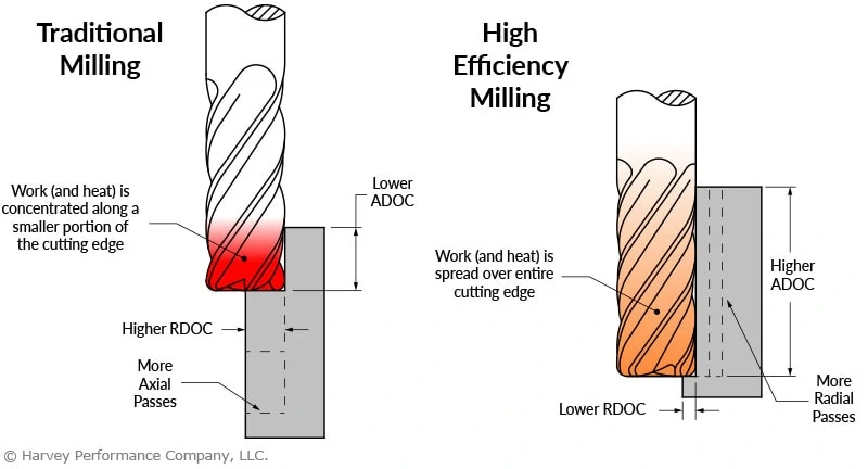
High Efficiency Milling (HEM) is a milling technique for roughing that utilizes a lower RDOC and a higher ADOC strategy. This spreads wear evenly across the cutting edge, dissipates heat, and reduces the chance of tool failure. This results in a greater ability to increase your MRR in machining, while maintaining and even prolonging tool life versus traditional machining methods.

HEM VS Traditional Milling

The image referenced below compares the differences between traditional milling and the newer High Efficiency Milling technique in achieving adequate material removal. A traditional milling strategy requires the application of work and heat along a smaller portion of the cutting edge, while the HEM technique disperses heat more evenly across the entire cutting edge. This method calls for more radial passes which utilize a larger portion of the cutting edge, as opposed to axial passes that lead to a higher likelihood of tool failure over time.

infographic showcasing difference between traditional and hem depths of cut and heat generated

Obviously, with higher MRR’s, chip evacuation becomes vitally important as more chips are evacuated in a shorter period of time. Utilizing a tool best suited for the operation – in terms of quality and flute count – will help to alleviate the additional workload. For softer materials lower flute count tools will traditionally be the best choice. The thinner core allows for deeper flute valleys which aid in enhanced chip evacuation and ultimately increased MRR. On the other hand, harder materials require higher flute count tools with shallower flute valleys. This leads to less material removed per tooth, however tool life is substantially increased over the historic usage of lower flute count tools in these materials.

Additionally, a tool coating optimized for your workpiece material can significantly help with chip packing. First, tool coatings increase heat resistance of the tool allowing for faster cutting speeds leading to increased MRR. Secondly, coatings increase the lubricity of the cutting tool allowing for enhanced chip evacuation and lessened friction. This enhanced chip evacuation allows for the most efficient metal removal rate possible.

Further, compressed air or coolant can help to properly remove chips from the tool and workpiece. There are different three types of coolant delivery methods one could utilize in increasing metal removal rate.

Compressed Air

While having no lubricity purpose, the air coolant delivery method is made to cool and clear chips. This method does not cool as effectively as other coolant-based solutions, however it is preferred for more sensitive materials where thermal shock is a concern.

Flood

Flooding is a low pressure coolant delivery method which creates lubricity in order to evacuate chips from a part. This is necessary to prevent chip recutting which is likely to damage a cutting tool. This method of delivery is the most common choice for the widest range of machining operations.

High Pressure

This method is similar to flood coolant, however it is used to instantly cool a part and blast chips away with a high pressure of delivery. While highly effective at chip evacuation, this option is most likely to damage or break more fragile cutting tools. High pressure coolant delivery is most often utilized in deep pocket machining and drilling operations due to its increased ability to flush chips.

High efficiency milling guidebook ad

In conclusion, optimizing workplace efficiency is vital to sustained success and continued growth in every business. This is especially true in machine shops, as even a very minor adjustment in operating processes can result in a massive boost in company revenue. Proper machining methods will boost MRR, minimize cycle times, prolong tool life, and maximize shop efficiency.

https://www.harveyperformance.com/wp-content/uploads/2018/01/Featured-Image-Optimizing-MRR-IMG.jpg 525 1400 Harvey Performance Company http://www.harveyperformance.com/wp-content/uploads/2018/08/Logo_HarveyPerformanceCompany-4.png Harvey Performance Company2018-01-15 10:25:152024-02-12 10:29:03Optimizing Material Removal Rates

What You Need to Know About Coolant for CNC Machining

December 5, 2017/9 Comments/in CNC Machining, Quick Tips, Tech Tips, Titan USA, Troubleshooting Tips/by Harvey Performance Company

Coolant in purpose is widely understood – it’s used to temper high temperatures common during machining, and aid in chip evacuation. However, there are several types and styles, each with its own benefits and drawbacks. Knowing which cnc coolant – or if any – is appropriate for your job can help to boost your shop’s profitability, capability, and overall machining performance.

Coolant or Lubricant Purpose

Coolant and lubricant are terms used interchangeably, though not all coolants are lubricants. Compressed air, for example, has no lubricating purpose but works only as a cooling option. Direct coolants – those which make physical contact with a part – can be compressed air, water, oil, synthetics, or semi-synthetics. When directed to the cutting action of a tool, these can help to fend off high temperatures that could lead to melting, warping, discoloration, or tool failure. Additionally, coolant can help evacuate chips from a part, preventing chip recutting and aiding in part finish.

Coolant can be expensive, however, and wasteful if not necessary. Understanding the amount of coolant needed for your job can help your shop’s efficiency.

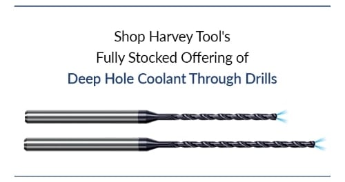
Click Here to Shop Harvey Tool’s Fully Stocked Offering of Deep Hole Coolant Through Drills

Types of Coolant Delivery

CNC coolant is delivered in several different forms – both in properties and pressure. The most common forms include air, mist, flood coolant, high pressure, and Minimum Quantity Lubricant (MQL). Choosing the wrong pressure can lead to part or tool damage, whereas choosing the wrong amount can lead to exhausted shop resources.

Air: Cools and clears chips, but has no lubricity purpose. Air coolant does not cool as efficiently as water or oil-based coolants. For more sensitive materials, air coolant is often preferred over types that come in direct contact with the part. This is true with many plastics, where thermal shock – or rapid expansion and contraction of a part – can occur if direct coolant is applied.

Mist: This type of low pressure coolant is sufficient for instances where chip evacuation and heat are not major concerns. Because the pressure applied is not great in a mist, the part and tool do not undergo additional stresses.

Flood: This low pressure method creates lubricity and flushes chips from a part to avoid chip recutting, a common and tool damaging occurrence.

High Pressure: Similar to flood coolant, but delivered in greater than 1,000 psi. This is a great option for chip removal and evacuation, as it blasts the chips away from the part. While this method will effectively cool a part immediately, the pressure can be high enough to break miniature diameter tooling. This method is used often in deep pocket or drilling operations, and can be delivered via coolant through tooling, or coolant grooves built into the tool itself. Harvey Tool offers Coolant Through Drills, while Titan USA proudly offers Coolant-Fed ThreadMills

Minimum Quantity Lubricant (MQL): Every machine shop focuses on how to gain a competitive advantage – to spend less, make more, and boost shop efficiency. That’s why many shops are opting for MQL, along with its obvious environmental benefits. Using only the necessary amount of coolant will dramatically reduce costs and wasted material. This type of lubricant is applied as an aerosol, or an extremely fine mist, to provide just enough coolant to perform a given operation effectively.

To see all of these coolant styles in action, check out the video below from our partners at CimQuest.

In Conclusion

CNC coolant is all-too-often overlooked as a major component of a machining operation. The type of coolant or lubricant, and the pressure at which it’s applied, is vital to both machining success and optimum shop efficiency. Coolant can be applied as compressed air, mist, in a flooding property, or as high pressure. Certain machines also are MQL able, meaning they can effectively restrict the amount of coolant being applied to the very amount necessary to avoid being wasteful.

https://www.harveyperformance.com/wp-content/uploads/2017/12/Feature-Image-Coolant-for-CNC-Machining-IMG.jpg 525 1400 Harvey Performance Company http://www.harveyperformance.com/wp-content/uploads/2018/08/Logo_HarveyPerformanceCompany-4.png Harvey Performance Company2017-12-05 15:09:342022-04-20 16:52:22What You Need to Know About Coolant for CNC Machining

Anderson Prototypes – Featured Customer

November 6, 2017/0 Comments/in Featured Customer/by Harvey Performance Company

Featured Image Courtesy of Anderson Prototypes

Anderson Prototypes is a custom machine shop in Port Moody, British Columbia. Working with everything from Titanium to Bamboo, they create mechanical mechanisms and working prototypes of new technology. By applying 25 years of experience with manual and CNC machinery, they craft amazing parts, some even bordering on impossible. The team at Anderson Prototypes works in a variety of industries, ranging from large-scale prototype work to small batch production, machine repair, and even movie and TV props.

Jim Anderson, a 30 year veteran of the manufacturing industry, is the Founder and Owner of Anderson Prototypes. We caught up with Jim and talked to him about some of the “impossible” projects his team likes to take, his experiences in the film industry, and his advice for the aspiring machinist.

Tell us a bit about your shop, how you got started, and what sort of products you manufacture.

I started in machining in 1985, as a full-time student in a machining class at a local community college. I spent years working in jobbing shops, plastic mold injection shops, and specialized start-up companies, scratch building a range of things from high-speed water “pouch” filling machines to hydrogen fuel-cells. Today I work with a wide range of clients including 3 submarine companies, a military contractor, companies that use custom built or modified ROVs and drones, food packaging companies, production companies needing film and TV props, and more.

What made you get into machining?

I have always been an actively creative person, and I enjoyed wood and machine shop in high school. I found a creative outlet for my talents to build and fix things inside the machine shop environment. I continue to study machines and items, to understand how they were made, and how it could be made better or simplified.

anderson prototypes

Photo Courtesy of: Anderson Prototypes

What is your favorite part of this profession?

I always enjoy creating something for a client that they have been dreaming of, sometimes for years. They come to me with a sketch on a napkin or a verbal idea, and I turn that dream into reality. When they come to pick it up and see it for the first time, the emotions are tremendous!

What sort of machines do you use in your shop?

I have 2 Tormach 1100 CNC mills, one 4 axis and the other 3 axis, a Sherline 2000, 4 axis CNC mill, a Frankenstein CNC lathe with a 8 station tool changer for small work, a Milltronics ML-17 CNC lathe, a Colchester Student Engine Lathe, and a smaller manual milling machine. I also have drill presses, tapping heads and tons of specialized fixturing and work holding devices, as well as a 60 ton hydraulic press and the specialized equipment that comes with it.

micro machining

Photo Courtesy of: Anderson Prototypes

Which materials do you work with in your shop?

Just about everything. Lots of plastics, PEEK, Delrin and Acrylic, aluminum, steels, stainless steels, carbon fiber, different woods, laminates, and more.

What sets Anderson Prototypes apart from the competition?

We often take on jobs that other shops won’t, due to our team’s large vision. We stand behind every piece we make and have zero returned items to date. Embodying both old-school traditions and cutting-edge technology, Anderson Prototypes believes that “Impossible is just an Opinion”. We work with a project from the very beginning to the time it is up and running at the client’s facility. We work with building very small detailed machines to unique and weird items that someone dreamed up and could not find anyone able to make. We also love to give back to the community. We have sponsored local high school and university students in competitions, and we have played a part in the Maker Community since Day One. We also made and donated a doggy wheelchair to a dog in need (YouTube), and we sponsor a local softball league.

How did you get into the entertainment/prop business?

Vancouver has a huge movie industry, and there are many people in my network that work in the industry. The need for various props, new equipment, and repairs can go up and down as movies are being filmed. The first job I did (I think), was for a movie called Space Buddies, the 4th or 5th entry in the Air Bud movie series. I made the Doggles (dog goggles), that the dog is wearing on the DVD cover. Most movies require a Non-Disclosure Agreements before any work is done, so I can’t talk about much, but I have made my impact on the screen, behind the scenes, and even live on stage. I also did a major prop for an Australian TV show that was apparently popular down under, so you never know where this work will take you!

micro machined

Photo Courtesy of: Anderson Prototypes

Who is the most famous contact that you have worked on a project with?

I have met many directors and producers of large budget films and TV shows. Unfortunately, because of the Non-Disclosure Agreements, I cannot mention any names.

Why is high-quality tool performance important to you?

I buy all my tooling from North America. I am lucky enough to have a solid carbide tooling manufacturer 5 miles from my shop, so I get quality endmills, made to order. When I need something specialized, Harvey is the only company I go to. When a tool does more than I expect, I make more money and have less stress. I count on that and become a return customer. For example, I used a .018″ Miniature End Mill (#73018-C3) on some acrylic parts I was making. There were 40 parts in total, all around the size of a stamp, with lots of tiny details, high tolerances, and very small features. I had the machine running at 15,500 RPM for 3 weeks, and I only broke one tool in that entire run. What a great tool!

What is your favorite process to work on as a machinist?

I really enjoy making something I have never worked on before, that new challenge. Often it seems that I am designing new items now more than ever. I have to do things that are not being done commercially and I stand behind it. So I might run the manual lathe, the CNC mill and then the CNC lathe on one part. I enjoy the variety.

anderson prototypes

Photo Courtesy of: Anderson Prototypes

Why is manufacturing your products in North America important to you?

American and Canadian-made products are very important to me. I purchase North American-made products like steel and aluminum, and bearings and fasteners all of kinds. I also access services locally, such as laser cutting, anodizing and powder coating, to support these local businesses. I feel its very important to the customer making the purchase that these are products my neighbors are helping to build.

If you could give one piece of advice to a new machinist ready to take the #PlungeIntoMachining, what would it be?

Take the time to take an accredited machine shop training course, like I did. It will give you all the groundwork to understand the real world of machining. I know a few fellas with small CNCs that can’t make a living because they don’t understand the depth of set-ups or work holding, for example, because they never learned from an expert. They can’t make parts fast enough, they charge 1/2 of what I do, and it takes then 3 times as long, so they simply can’t compete with me. Just be aware that it doesn’t happen overnight; I was a Journeyman Machinist for over 30 years, and still ask for help from my mentors occasionally. Oh, and find yourself a quality machine. Find a good used HAAS, or OKK, or something made in the US, UK or Europe. Your clients will respect you more and it will work longer and more accurately.

Is there anything else you would like to share with the In The Loupe community?

I am grateful for the education I have received from the many journeyman machinists, engineers, mechanics, electricians, pilots, sea captains and more who I have worked beside in my years. I am happy to share and offer problem-solving, sometimes for free, other times at consultation rates. When a young eager person asks me a question, I do the best I can to answer it in a way that benefits them long term. Sometimes they don’t like the answer, but I tell them to come back in 6 months and tell me how it went. That’s when the rubber hits the road.

anderson prototypes

Photo Courtesy of: Anderson Prototypes


Would you like to be considered for a future “Featured Customer” blog? Click here to submit your information.
Photos courtesy of Anderson Prototypes.

https://www.harveyperformance.com/wp-content/uploads/2017/11/Featured-Image-Anderson-Prototypes-IMG.jpg 525 1400 Harvey Performance Company http://www.harveyperformance.com/wp-content/uploads/2018/08/Logo_HarveyPerformanceCompany-4.png Harvey Performance Company2017-11-06 15:10:252022-06-08 11:36:32Anderson Prototypes – Featured Customer

Optimize Roughing With Chipbreaker Tooling

October 24, 2017/8 Comments/in CNC Machining, Helical Solutions, Tool Information Guides, Tool Selection, Troubleshooting Tips/by Harvey Performance Company

What is Chipbreaker Tooling?

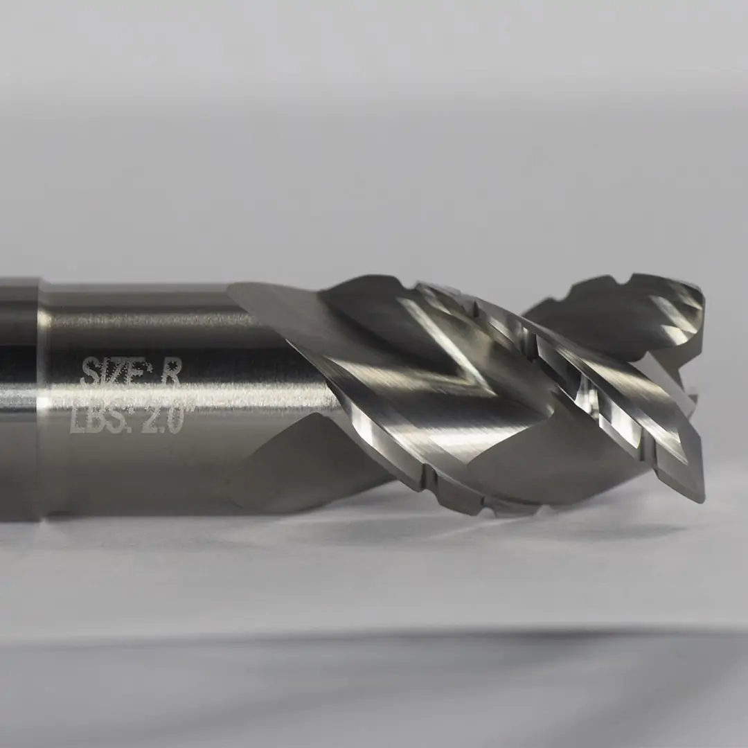
Chipbreaker End Mills feature unique notch profiles, creating a serrated cutting edge. These dividers break otherwise long, stringy chips into small, easily-managed swarf that can be cleanly evacuated from the part. But why is a chipbreaker necessary for some jobs, and not others? How does the geometry of this unique tool impact its proper running parameters? In this post, we’ll answer these questions and others to discover the very real benefits of this unique cutting geometry.

up close image of chipbreaker end mill

How Chipbreaker Tooling Works

As a tool rotates and its cutting edge impacts a workpiece, material is sheared off from a part, creating chips. When that cutting process is interrupted, as is the case with breaks in the cutting portion of the tool, chips become smaller in length and are thus easier to evacuate. Because the chipbreakers are offset flute-to-flute, a proper, flat surface finish is achieved as each flute cleans up any excess material left behind from previously passed flutes.

Benefits of Chipbreaker Tooling

Machining Efficiency

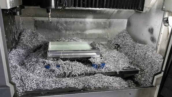
When chips are removed from the part, they begin to pile in the machine. For extensive operations, where a great deal of material is hogged out, chip accumulation can very rapidly get in the way of the spindle or part. With larger chips, accumulation occurs much faster, leaving machinists to stop their machine regularly to remove the waste. As any machinist knows, a stopped machine equates to lost money.

small metal chips in cnc machine resulting from the use of a chipbreaker end mill

Prolonged Tool Life

Inefficient chip evacuation can lead to chip recutting, or when the the tool impacts and cuts chips left behind during the machining process. This adds stresses on the tool and accelerates rate of wear on the cutting edge. Chipbreaker tooling creates small chips that are easily evacuated from a part, thus minimizing the risk of recutting.

Accelerated Running Parameters

A Harvey Performance Company Application Engineer recently observed the power of a chipbreaker tool firsthand while visiting a customer’s shop in Minnesota. The customer was roughing a great amount of 4340 Steel. Running at the parameters below, the tool was able to run uninterrupted for two hours!

Helical Part No.33737
Material4340 Steel
ADOC2.545″
RDOC.125″
Speed2,800 RPM
Feed78 IPM
Material Removal Rate24.8 Cubic In/Min


Chipbreaker Product Offering

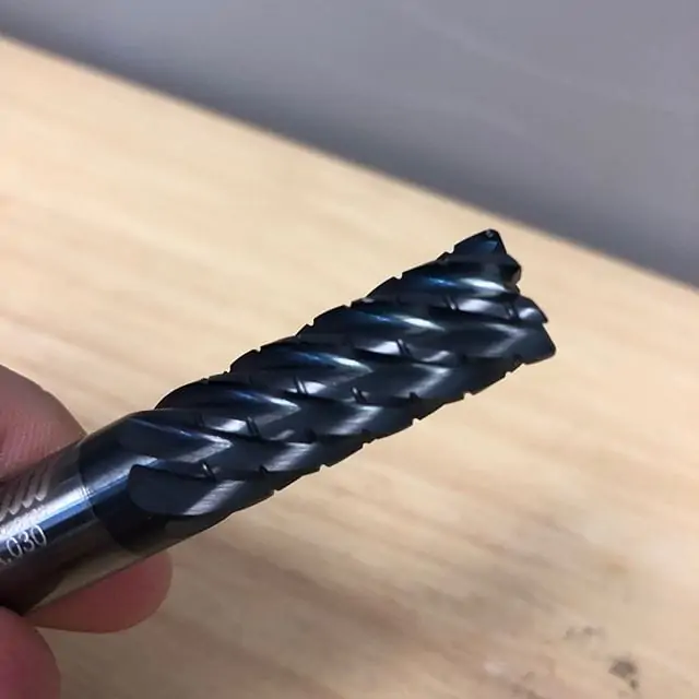
Chipbreaker Geometry is often utilized in aluminum jobs and with other materials where long, stringy chips are common. Materials that produce a powdery chip, such as graphite, should not be machined with a chipbreaker tool, as chip evacuation would not be a concern. Helical Solutions’ line of chipbreaker tooling includes a 3-flute option for aluminum and non-ferrous materials, and its reduced neck counterpart. Additionally, Helical offers a 4-flute rougher with chipbreaker geometry for high-temp alloys and stainless steels. Harvey Tool’s expansive product offering includes a composite cutting end mill with chipbreaker geometry.

helical solutions 7 flute chipbreaker end mill cutting edges
Helical Solutions 7 Flute Chipbreaker

In Summary

Chipbreaker geometry, or grooves within the cutting face of the tool, break down chips into small, manageable pieces during the machining process. This geometry can boost shop efficiency by minimizing machine downtime to clear large chips from the machining center, improve tool life by minimizing cutting forces exerted on the tool during machining, and allow for more accelerated running parameters.

https://www.harveyperformance.com/wp-content/uploads/2017/10/Feature-Image-Chipbreaker-Tooling-IMG.jpg 600 1599 Harvey Performance Company http://www.harveyperformance.com/wp-content/uploads/2018/08/Logo_HarveyPerformanceCompany-4.png Harvey Performance Company2017-10-24 16:52:132024-03-07 16:04:28Optimize Roughing With Chipbreaker Tooling

Speeds and Feeds 101

October 2, 2017/15 Comments/in CNC Machining, Machining 101, Machining Techniques, Milling, Quick Tips/by Harvey Performance Company

Understanding Speeds and Feed Rates

NOTE: This article covers speeds and feed rates for milling tools, as opposed to turning tools.

Before using a cutting tool, it is necessary to understand tool cutting speeds and feed rates, more often referred to as “speeds and feeds.” Speeds and feeds are the cutting variables used in every milling operation and vary for each tool based on cutter diameter, operation, material, etc.

Understanding the right speeds and feeds for your tool and operation before you start machining is critical. These are to be used to set baselines for a particular tool, ensuring proper performance without compromising part finish and tool life.

NOTE: This article covers speeds and feed rates for milling tools, as opposed to turning tools.

Understanding SFM Calculations

It is first necessary to define each of these factors. Cutting speed, also referred to as surface speed, is the difference in speed between the tool and the workpiece, expressed in units of distance over time known as SFM (surface feet per minute).

For set-ups with stationary workpieces, SFM is the speed at which a tool moves across the part in the cut. The speed difference must be calculated in set ups where the part and tool are both moving in multi-axis machining set-ups.

Surface Foot is based on the various properties of the given material. Speed, referred to as Rotations Per Minute (RPM) is based off of the SFM and the cutting tool’s diameter. As SFM is tied to the properties of a material, it does not change based upon the operation being performed and remains constant despite changes in chip load calculation.

How Do You Calculate Surface Feet per Minute (SFM)?

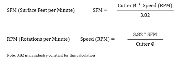
The SFM calculation utilizes the industry standard of 3.82. Here, the cutter diameter of the chosen tool is multiplied by the speed or RPM. This figure is then divided by 3.82 to generate the SFM or Surface Feet per Minute.

Feed Rate and Chip Load Calculations

While speeds and feeds are common terms used in the programming of the cutter, the ideal running parameters are also influenced by a myriad of other variables. As speeds and feeds must be well-matched to be effective, the speed of the cutter is used in the calculation of the cutter’s feed rate, measured in Inches Per Minute (IPM).

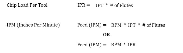
The other part of the equation is the chip load, or material being removed per revolution. It is important to note that chip load per tooth and chip load per tool are different:

  • Chip load per tooth is the appropriate amount of material that one cutting edge of the tool should remove in a single revolution. This is measured in Inches Per Tooth (IPT).
  • Chip load per tool is the appropriate amount of material removed by all cutting edges on a tool in a single revolution. This is measured in Inches Per Revolution (IPR).
speeds and feeds formula in both sfm and rpm
HEM Guidebook Ad

A chip load that is too large can pack up chips in the cutter, causing poor chip evacuation and eventual breakage. A chip load that is too small can cause rubbing, chatter, tool deflection, and a poor overall cutting action. Finding the correct balance will not only allow for the most efficient cut possible, but also ensures the most efficiency in regard to tool wear. When calculating chip load per tool or IPR, the per tooth chip load is aptly multiplied by the number of flutes on the tool itself.

chip load and ipm calculations

Material Removal Rate

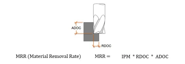
Material Removal Rate (MRR), while not part of the cutting tool’s program, is a helpful way to calculate a tool’s efficiency. MRR takes into account two very important running parameters: Axial Depth of Cut (ADOC), or the distance a tool engages a workpiece along its centerline, and Radial Depth of Cut (RDOC), or the distance a tool is stepping over into a workpiece.

The MRR calculation (seen below) relies on the calculated feed rate. The feed rate (IPM) is multiplied by the radial and axial depths of cut to produce the rate of removal.

The tool’s depth of cuts and the rate at which it is cutting can be used to calculate how many cubic inches per minute (in3/min) are being removed from a workpiece. This equation is extremely useful for comparing cutting tools and examining how cycle times can be improved. Decreased cycle times leads to higher productivity within a shop, which is what all machinists aim for during production.

Adjusting depths of cut can decrease time in cut and overall production time, freeing up machines for additional manufacturing. An example of depth of cut adjustment is seen in High Efficiency Milling, where RDOC is decreased and ADOC is increased. In this method, MRR is increased while also reducing tool wear, leading to higher productivity and more parts per tool.

mrr calculation and illustration of adoc and rdoc

Speeds and Feeds In Practice

While many of the cutting parameters are set by the tool and workpiece material, the depths of cut taken also affect the feed rate of the tool. The depths of cuts are dictated by the operation being performed – this is often broken down into slotting, roughing, and finishing. Though there are many other more specific types of operations.

These unique operations utilize much different depths of cut, with industry standardized terms as description. Slotting can be described as utilizing 180° of the diameter of the tool engaged in the cut.

Roughing on the other hand will typically disperse both ADOC and RDOC relatively evenly. Finally, finishing operations will use substantially more axial depths of cut in relation to radial, leaving the best finish possible on the workpiece.

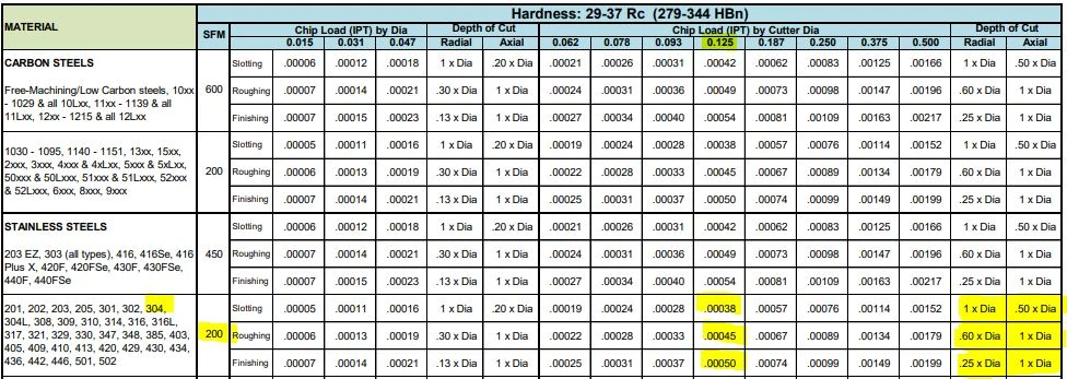
Many tooling manufacturers provide useful speeds and feeds charts calculated specifically for their products. For example, Harvey Tool provides the following chart for a 1/8” diameter end mill, tool #50308.

A customer can find the SFM for the material on the left, in this case 304 stainless steel (highlighted in yellow). The chip load (per tooth) can be found by intersecting the tool diameter on the top (blue heading) with the material and operations (based on axial and radial depth of cut), highlighted in the image below.

carbon and stainless steels hardness chart with corresponding cnc running parameters

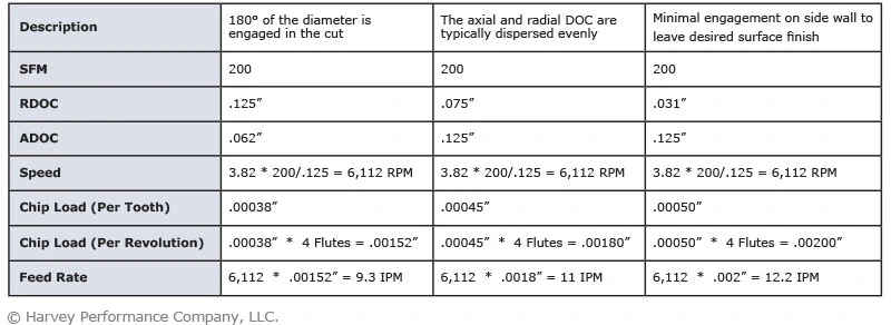
The following table calculates the speeds and feeds for this tool (#50308) and material (304 Stainless) for each operation, based on the chart above:

speeds and feeds calculation chart

Earn an Immediate Boost to Shop Efficiency: Download the HEM Guidebook Today

Other Important Considerations

  • Spindle Speed Cap
  • Effective Cutter Diameter
  • Non-Linear Paths

Each operation recommends a unique chip load per the depths of cut depending on the operation, thus resulting in different feed rates for the desired application. Since the SFM is based on the material, it will always remain constant for each of the three defined operations.

Milling speeds between materials vary drastically. For example, the milling speed for stainless will differ than that of much softer aluminum. Therefore, it is always important to factor in materials when examining speeds and feeds chart and performing calculations.

Spindle Speed Cap

As shown above, the cutter speed (RPM) is defined by the SFM (based on material) and the cutter diameter. With miniature tooling and/or certain materials the speed calculation sometimes yields an unrealistic spindle speed.

For example, a .047” cutter in 6061 aluminum (SFM 1,000) would return a speed of ~81,000 RPM. Since this speed is only attainable with high speed air spindles, the full SFM of 1,000 may not be achievable. In a case like this, it is recommended that the tool is run at the machine’s max speed (that the machinist is comfortable with) and that the appropriate chip load for the diameter is maintained. This produces optimal parameters based on the machine’s top speed.

All machines are unique and provide different max speed, therefore these calculations will vary based on machine capabilities within your shop.

Effective Cutter Diameter

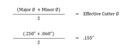
On angled tools the cutter diameter changes along the LOC. For example, Helical tool #07001, a flat-ended chamfer cutter with helical flutes, has a tip diameter of .060” and a major/shank diameter of .250”. In a scenario where it was being used to create a 60° edge break, the actual cutting action would happen somewhere between the tip and major/shank diameters. To compensate, the equation below can be used to find the average diameter along the chamfer.

effective cutter diameter calculation

Using this calculation, the effective cutter diameter is .155”, which would be used for all Speeds and Feeds calculations.

Non-linear Path

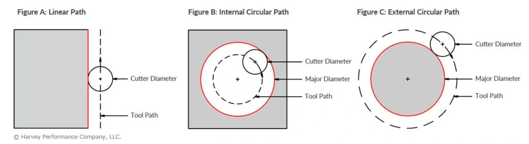
Feed rates assume a linear motion. However, there are cases in which the path takes an arc, such as in a pocket corner or a circular interpolation. Just as increasing the DOC increases the angle of engagement on a tool, so does taking a nonlinear path. For an internal corner, more of the tool is engaged and, for an external corner, less is engaged. The feed rate must be appropriately compensated for the added or lessened engagement on the tool to provide the most effective and desired IPM for the chosen application.

In the below graphic, Figure A is showcasing a linear path on a part, with a standard engagement. Figure’s B and C demonstrate the increase and decrease of engagement in non-linear, circular toolpaths. Utilizing identical feed rates between the three paths would generate three wildly different IPMs despite similar setups.

infographic showcasing the differences between linear and non-linear machine paths

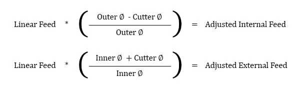
This adjustment is even more important for circular interpolation. Take, for example, a threading application involving a cutter making a circular motion about a pre-drilled hole or boss. For internal adjustment, the feed rate must be lowered to account for the additional engagement. For external adjustment, the feed rate must be increased due to less tool engagement.

An adjustment in internal feed subtracts the differences in cutter diameters from the differences in outer diameters before dividing by the outer dia. difference. On the other hand, adjusting for external feed adds the differences between cutter diameters to the differences in inner diameters before dividing by the inner dia. difference.

adjusted internal and external feed calculation

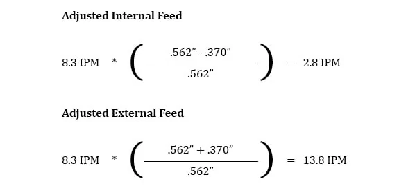
Take this example, in which a Harvey Tool threadmill #70094, with a .370” cutter diameter, is machining a 9/16-18 internal thread in 17-4 stainless steel. The calculated speed is 2,064 RPM and the linear feed is 8.3 IPM. The thread diameter of a 9/16 thread is .562”, which is used for the inner and outer diameter in both adjustments. After plugging these values into the equations below, the adjusted internal feed becomes 2.8 IMP, while the external feed becomes 13.8 IPM.

adjusted internal and external feed calculations with examples

SFM in Conclusion

These calculations are useful guidelines for running a cutting tool optimally in various applications and materials. However, the tool manufacturer’s recommended parameters are the best place to start for initial numbers and to set a baseline for the best tool performance.

After that, it is up to the machinist’s eyes, ears, and experience to help determine the best running parameters, which will vary by set-up, tool, machine, and chosen material. No operation is exactly the same, and nothing occurs in a vacuum. Experience and continued learning will always aid machinists in ensuring the most efficient performance possible in the cut.

The following links have the most up to date information on running parameters for Harvey Tool, Helical, Titan USA, and CoreHog CNC products.

https://www.harveyperformance.com/wp-content/uploads/2017/10/Feature-Image-Speeds-Feeds-IMG.jpg 525 1400 Harvey Performance Company http://www.harveyperformance.com/wp-content/uploads/2018/08/Logo_HarveyPerformanceCompany-4.png Harvey Performance Company2017-10-02 17:00:172025-02-14 10:48:58Speeds and Feeds 101

Why Flute Count Matters

September 26, 2017/20 Comments/in CNC Machining, Helical Solutions, High Efficiency Milling, Tech Tips, Tool Geometry, Tool Selection/by Harvey Performance Company

One of the most important considerations when choosing an end mill is determining which flute count is best for the job at hand. Both material and application play an important role in this critical part of the tool selection process. Understanding the effects of flute count on other tool properties, and how a tool will behave in different situations is an essential consideration in the tool selection process. As end mills have become more and more advanced, certain standards have been created for flute counts in certain materials. While there is obvious overlap due to a myriad of factors, proper flute count is critical for machining success and ensuring you are making the most of your end mill and it’s associated MRR.

Machining Advisor Pro (MAP) Takes Flute Count Into Consideration When Helping You Dial In Running Parameters.

Click Here to Get Started.

Tool Geometry Basics

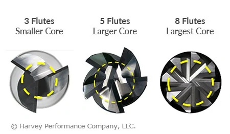
Generally, tools with more flutes have a larger core and smaller flute valleys than tools with fewer flutes.  More flutes with a larger core can provide both benefits and restrictions depending on the application.  Simply put, a larger core is directly proportional to tool strength; the larger the core, the stronger a tool will be.  In turn, a larger core also reduces the flute depth of a tool, restricting the amount of space for chips to exist.  This can cause issues with chip packing in applications requiring heavy material removal.  However, these considerations only lead us part way when making a decision on which tool to use, and when.

3, 5, and 8 flute end mills and their core sizes in relation to flute valleys

Material Considerations

Traditionally, end mills came in either a 2 flute or 4 flute option.  The widely accepted rule of thumb was to use 2 flutes for machining aluminum and non-ferrous materials, and 4 flutes for machining steel and harder alloys.  As aluminum and non-ferrous alloys are typically much softer than steels, a tool’s strength is less of a concern, a tool can be fed faster, and larger material removal rates (MRR) is facilitated by the large flute valleys of 2 flute tools.

Consequently, ferrous materials are typically much harder, and require the strength of a larger core.  Feed rates are slower, resulting in smaller chips, and allowing for the smaller flute valleys of a larger core tool.  This also allows for more flutes to fit on the tool, which in turn increases productivity.

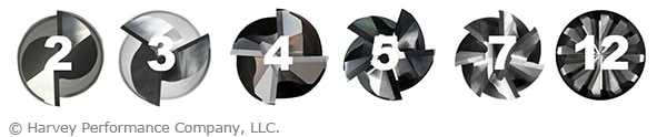
end mill flute count comparisons

Recently, with more advanced machines and toolpaths, higher flute count tools have become the norm in manufacturing.  Non-ferrous tooling has become largely centered on 3 flute tools. This has created a slight advantage over 2 flute tools by increasing productivity while still affording proper chip evacuation. The softness of non-ferrous materials affords a much deeper flute valley. As previously discussed, this allows the tool to be fed much faster than in ferrous materials. Adding an additional flute increases the productivity of the tool, while still affording machinists faster feed rates.

Ferrous tooling has taken a step further and progressed not only to 5 and 6 flutes, but up to 7 flutes and more in some cases.  With a wider range of hardness, sometimes at the very top of the Rockwell hardness scale, many more flutes have allowed longer tool life, less tool wear, stronger tools, and less deflection.  All of this results in more specialized tools for more specific materials. Material specific tooling combines proper flute counts with coatings that aid in lubricity and heat generation to ensure the most effective end mill possible in the material being machined. The end result is higher MRR and increased productivity across the entire range of ferrous materials that machinists will work with in their shops.

Running Parameters

Just as material considerations will have an impact on the tool you choose, operation type and depth of cut requirements may also have a big impact on the ideal number of flutes for your application.  In roughing applications, lower flute counts may be desirable to evacuate large amounts of chips faster with larger flute valleys.  That said, there is a balance to find, as modern toolpaths such as High Efficiency Milling (HEM) can achieve extreme MRR with a very small step over, and a higher number of flutes.  In a more traditional sense, higher flute counts are great for finishing operations where very small amounts of material are being removed, and greater finish can be achieved with more flutes, not worrying as much about chip evacuation as that phase has already been accomplished during roughing.

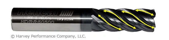
helical end mill with lines showcasing the flute valleys

Flute count plays a big role in speeds and feeds calculation as well.  One common rule of thumb is “more flutes, more feed,” but this can be a very detrimental misconception.  Although true in some cases, this is not an infinitely scalable principle.  As stated previously, increasing the number of flutes on a tool limits the size that the flute valleys can be.  While adding a 5th flute to a 4 flute tool theoretically gives you 25% more material removal per revolution with an appropriately increased feed rate, feeding the tool that much faster may overload the tool.  The 25% increase in material removal is more likely closer to 10-15%, given the tool is exactly the same in all other specifications.  Higher flute count tools may require speeds and feeds to be backed off so much in some cases, that a lower flute count may be even more efficient.  Finding the right balance is key in modern milling practices. Consulting a tooling manufacturer’s speeds and feeds will be the perfect starting point, and then machinists can make changes as they see fit to properly accomplish the job at hand.

In all, the importance of flute count identification is critical to continued success at the spindle. Different materials have different strength requirements as well as variability in how much material can be appropriately removed per tooth.

https://www.harveyperformance.com/wp-content/uploads/2017/09/Feature-Image-Why-Flute-Count-Matters-IMG.jpg 525 1400 Harvey Performance Company http://www.harveyperformance.com/wp-content/uploads/2018/08/Logo_HarveyPerformanceCompany-4.png Harvey Performance Company2017-09-26 15:00:092023-12-01 14:20:29Why Flute Count Matters

Avoid Composite Delamination With Compression Cutters

September 12, 2017/0 Comments/in CNC Machining, Composites, How-To's, Machining Techniques, Tool Selection, Troubleshooting Tips/by Harvey Performance Company

Composites are a group of materials made up of at least two unique constituents that, when combined, produce mechanical and physical properties favorable for a wide array of applications. These materials usually contain a binding ingredient, known as a matrix, filled with particles or fibers called reinforcements. Composites have become increasingly popular in the Aerospace, Automotive, and Sporting Goods industries because they can combine the strength of metal, the light weight of plastic, and the rigidity of ceramics.

Unfortunately, composite materials present some unique challenges to machinists. Many composites are very abrasive and can severely reduce tool life, while others can melt and burn if heat generation is not properly controlled. Even if these potential problems are avoided, the wrong tool can leave the part with other quality issues, including delamination.

While composites such as G10 and FR4 are considered “fibrous”, composites can also be “layered,” such as laminated sheets of PEEK and aluminum. Layered composites are vulnerable to delamination, when the layers of the material are separated by a tool’s cutting forces. This yields less structurally sound parts, defeating the purpose of the combined material properties in the first place. In many cases, a single delaminated hole can result in a scrapped part.

Using Compression Cutter End Mills in Composite Materials

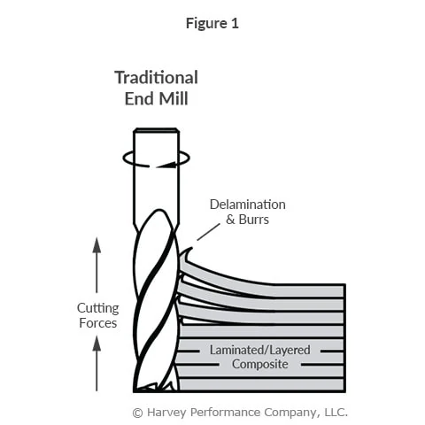
Composite materials are generally machined with standard metal cutting end mills, which generate exclusively up or down cutting forces, depending on if they have right or left hand flute geometry. These uni-directional forces cause delamination (Figure 1).

infographic of delamination with traditional end mill due to upward cutting forces

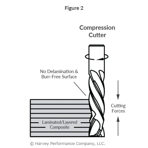
Conversely, compression cutters are designed with both up and down-cut flutes. The top portion of the length of cut, closest to the shank, has a left hand spiral, forcing chips down. The bottom portion of the length of cut, closest to the end, has a right hand spiral, forcing chips up. When cutting, the opposing flute directions generate counteracting up-cut and down-cut forces. The opposing cutting forces stabilize the material removal, which compresses the composite layers, combatting delamination on the top and bottom of a workpiece (Figure 2).

infographic of no delamination due to even cutting forces with compression cutter end mill

Since compression cutters do not pull up or press down on a workpiece, they leave an excellent finish on layered composites and lightweight materials like plywood. It is important to note, however, that compression cutters are suited specifically to profiling, as the benefits of the up and down-cut geometry are not utilized in slotting or plunging operations.

Something as simple as choosing a tool suited to a specific composite material can have significant effects on the quality of the final part. Consider utilizing tools optimized for different composites and operations or learn how to select the right drill for composite holemaking.

https://www.harveyperformance.com/wp-content/uploads/2017/09/Feature-Image-Compression-Cutters-IMG.jpg 525 1400 Harvey Performance Company http://www.harveyperformance.com/wp-content/uploads/2018/08/Logo_HarveyPerformanceCompany-4.png Harvey Performance Company2017-09-12 16:00:532025-11-12 16:00:14Avoid Composite Delamination With Compression Cutters

Key Tool Holding Considerations

September 5, 2017/0 Comments/in CNC Machining, Getting Started, Machining 101, Machining Techniques, Tools In Action, Troubleshooting Tips/by Harvey Performance Company

Each tool holder style has its own unique properties that must be considered prior to beginning a machining operation. A secure machine-to-tool connection will result in a more profitable shop, as a poor connection can cause tool runout, pull-out, scrapped parts, damaged tools, and exhausted shop resources. An understanding of tool holders, shank features, and best practices is therefore pivotal for every machinist to know to ensure reliable tool holding.

Types of Tool Holding

The basic concept of any tool holder is to create a compression force around the cutting tool’s shank that is strong, secure, and rigid. These come in a variety of styles, each with its own spindle interface, taper for clearance, and compression force methods.

Mechanical Spindle Tightening

The most basic way in which spindle compression is generated is by simple mechanical tightening of the holder itself, or a collet within the holder. The downside of this mechanical tightening method of the spindle is its limited number of pressure points. With this style, segments of a collet collapse around the shank, and there is no uniform, concentric force holding the tool around its full circumference.

end mill in tool holder within a cnc machine

Hydraulic Tool Holders

Other methods create a more concentric pressure, gripping the tool’s shank over a larger surface area. Hydraulic tool holders create this scenario. They are tightened via a pressurized fluid inside the bore of the holder, creating a more powerful clamping force on the shank.

Shrink Fit Tool Holders

Shrink fit tool holders are another high quality tool holding mechanism. This method works by using the thermal properties of the device to expand its opening slightly larger than the shank of the tool. The tool is placed inside the holder, after which the holder is allowed to cool, contracting down close to its original size and creating a tremendous compressive force around the shank. Since the expansion of the bore in the tool holder is minuscule, a tight tolerance is needed on the shank to ensure it can fit every time. Shank diameters with h6 tolerances ensure the tool will always work properly and reliably with a shrink fit holder.

A post shared by Helical Tool (@helicaltools) on Aug 9, 2017 at 5:42am PDT

Types of Shank Modifications

Along with choosing correctly when it comes to tool holding options, tool shanks can be modified to promote a more secure machine-to-tool connection. These modifications can include added grooves on the shank, flats, or even an altered shank surface to aid in gripping strength.

Weldon Flats

A Weldon flat can be used to create additional strength within the tool holder. The tool holder locks a tool in place with a set screw pushing on a flat area on the tool shank. Weldon flats offer a good amount of pull-out prevention due to the set screw sitting in the recessed shank flat. Often seen as an outdated method of tool holding, this method is most effective for larger, stronger tools where runout is less of a concern.

ToughGRIP Shanks

Helical Solutions offers a ToughGRIP shank modification to its customers, which works by increasing the friction of the shank – making it easier to grip for the tool holder. This modification roughs the shank’s surface while maintaining h6 shrink fit tolerance.

Haimer Safe-Lock™

In the Haimer Safe-Lock system, special drive keys in the chuck interface with grooves in the shank of the tool to prevent pull-out. The end mill effectively screws into the tool holder, which causes a connection that only becomes more secure as the tool is running. Haimer Safe-Lock™ maintains h6 shank tolerances, ensuring an even tighter connection with shrink fit holders.

haimer safe-lock tool holder up close

Key Takeaways

While choosing a proper cutter and running it at appropriate running parameters are key factors to a machining operation, so too is the method used. If opting for an improper tool holding method, one can experience tool pull-out, tool runout, and scrapped jobs. Effective tool holding will prevent premature tool failure and allow machinists to feel confident while pushing the tool to its full potential.

https://www.harveyperformance.com/wp-content/uploads/2017/09/Feature-Image-Tool-Holder-Considerations-IMG.jpg 525 1400 Harvey Performance Company http://www.harveyperformance.com/wp-content/uploads/2018/08/Logo_HarveyPerformanceCompany-4.png Harvey Performance Company2017-09-05 16:54:202024-02-12 11:21:42Key Tool Holding Considerations

Weiss Watches – Featured Customer

September 4, 2017/2 Comments/in Featured Customer/by Harvey Performance Company

Featured Image Courtesy of Weiss Watch Company

Weiss Watch Company is restoring prestige to American watchmaking. They design and build timepieces with mechanical movements by hand in Los Angeles, California. Each timepiece is individually assembled in America. Their practices merge historical techniques and modern technological advances, with every process perfected by a Swiss-trained and certified American watchmaker. Weiss Watch Company strives to increase the percentage of domestic sourcing with each edition, and is the only company resurrecting industry practices that have not been active in the United States for decades.

Grant Hughson is a Manufacturing Engineer at Weiss Watch Company. Grant “lives and breathes” manufacturing, currently working in his spare time as a Manufacturing Instructor at Saddleback College. We spoke to Grant for this latest featured customer blog about the watch-making process, his experiences in the industry, and his thoughts on the state of American manufacturing.

weiss watches

Photo Courtesy of: Weiss Watch Company

What made you get into machining?

I grew up with a love for finely machined products, like watches, guns, and fishing gear. I also loved car racing, and a lot of the modifications on the cars are machined from various materials. So, from a young age, I was obsessed with the work that went into these products, and knew I wanted to be a part of the manufacturing industry.

What is your favorite part of this profession?

I love the entire manufacturing process. It always starts with a dream, or an idea. Then you take that idea and turn it into a drawing, and soon after, you’ll be modeling it. The best part is when you go to actually machine the part, and watch your original idea turn into a tangible part or product.

watchmaking

Photo Courtesy of: Weiss Watch Company

What is the most challenging part of the watch-making process?

There are a few challenging parts of the watch-making process, starting with the super-tight tolerances. Surface finish is also extremely important, and can be difficult to nail. Many surface finishes in watchmaking are visual, so roughness can be deceiving. We also were forced to design all of our workholding from scratch, as nothing currently existed in the market that would work for our machining process.

You mentioned your tight tolerances. What tolerances do you typically work in?

My tolerances are in the tenths. The holes that hold the jewels (watch bearings) are +0.0002, -0.

weiss watches

Photo Courtesy of: Weiss Watch Company

What sort of machines do you have in your shop?

We have a 3 axis vertical milling machine and a 9 axis Swiss style lathe in the shop.

What type of materials do you work in?

We work in steel, stainless steel, aluminum, brass, and titanium every day. It is a wide variety, but it keeps things interesting!

How have Harvey Tool products impacted your overall shop performance?

Harvey Tools have been great tools for me. I do a lot of prototype work, and constantly need odd sized tools or specialty profiles to finish a job. Thankfully, the Harvey Tool selection is HUGE. Somehow you guys always have what I need!

Tell us about your favorite project that Harvey Tools helped to create.

I love what I do everyday, so my favorite project is an ongoing one; making watches!

watchmaking tools

Photo Courtesy of: Weiss Watch Company

Why is high quality tool performance important to you?

It’s a must! Tool to tool accuracy and performance is vital in this business, especially with our extremely tight tolerances. High quality tools make sure that we get the same performance time after time without needing to scrap parts. This saves us valuable time and money.

What is your favorite process to work on as a machinist?

I really enjoy fixture design. Holding small parts for fixture design is an art! If it’s too tight, they’re smashed. If it’s too loose, see you later; your part is gone!

As a manufacturing engineer, I also enjoy the programming aspect of CNC machining. Being able to program the toolpaths and turn my programming skills into tangible parts is why I got into this business.

weiss watches

Photo Courtesy of: Weiss Watch Company

If you were stranded on a desert island with only one Harvey Tool or Helical tool, which would it be, and why?

It would have to be the Harvey 1/4″  30° engraving tool. I could mount it to the end of a stick. It would make for a hell of a spear!

Why is manufacturing products in America important to you?

Manufacturing products in America is a crucial part of the success and security of our business. When someone else makes your parts, its not hard for them to make a competing product. Making everything on-site keeps our proprietary information safe.

If you could give one piece of advice to a new machinist ready to take the #PlungeIntoMachining, what would it be?

Ask a lot of questions and never stop learning. It’s not easy but it’s worth it. If you consider yourself a maker or inventor, it’s the only place to be! Manufacturing is awesome, and anyone who tells you different is on the way out. Keep up the good work, and keep manufacturing your products in America!

weiss watches

Photo Courtesy of: Weiss Watch Company

Would you like to be considered for a future “Featured Customer” blog? Click here to submit your information.
Photos courtesy of Weiss Watch Company.

https://www.harveyperformance.com/wp-content/uploads/2017/09/Featured-Image-Weiss-Watches-IMG.jpg 525 1400 Harvey Performance Company http://www.harveyperformance.com/wp-content/uploads/2018/08/Logo_HarveyPerformanceCompany-4.png Harvey Performance Company2017-09-04 09:38:382022-06-08 11:27:41Weiss Watches – Featured Customer
Page 8 of 10«‹678910›»
BLOG HOME

Search In the Loupe

More results...

Browse by Topic

How-To’s
Technical Tips
Tools In Action
Featured Customers
Tool Guides

Free Drilling Guidebook

DOWNLOAD

Recent Posts

  • Machining a Complex Part with Harvey Tool
  • Drill Substrate Guide: HSS vs Cobalt vs Carbide
  • The Key Differences Between Helical’s Tool Coatings

Stay In The Loupe!

Sign up to receive a monthly recap of:
– The latest machining solutions
– Machining tips and tricks
– A recap of our most popular posts

SIGN UP

Contact Us


Address
428 Newburyport Turnpike
Rowley, MA 01969

Website
www.harveyperformance.com

Phone
Harvey Tool Tech: 1.800.645.5609
Helical Solutions Tech: 1.866.543.5422
Micro 100 Tech: 1.800.421.8065
Titan USA Tech: 1.888.482.6872

Email
[email protected]
[email protected]
[email protected]
[email protected]
[email protected]

CONTACT US

428 Newburyport Turnpike
Rowley, MA 01969-1729

844-393-8665

[email protected]

HARVEY PERFORMANCE

Company Overview
Our Unique Strengths
Industries Served
Careers
Sustainability
Privacy Policy

OUR BRANDS

Harvey Tool
Helical Solutions
Micro 100
Titan USA
CoreHog
Valor Holemaking

OUR BRANDS

ATA Air Tools
ATA SGSPRO
Garryson
Industrial Tooling Corporation (ITC)
Karnasch
Van Hoorn Carbide

Copyright © 2022 Harvey Performance Company, LLC
  • Link to LinkedIn
  • Link to Facebook
Scroll to top Scroll to top Scroll to top