Harvey Performance Company
  • About Us
    • Company Overview
    • Our Unique Strengths
    • Our Partners
    • Our History
    • Our Locations
    • Sustainability
    • Giving Back
      • Giving Back
      • One Tree Planted
    • News
      • News
      • Press
  • Our Brands
    • Harvey Tool
    • Helical Solutions
    • Micro 100
    • Titan USA
    • CoreHog
    • Valor Holemaking
    • ATA Air Tools
    • ATA SGSPRO
    • Garryson
    • ITC
    • Karnasch
    • Van Hoorn Carbide
  • Products
    • Milling
    • Drilling
    • Grinding
    • Micro Tools
    • Sinking
    • Sawing
    • Composite Tools
    • Threading
    • Turning
    • Beveling
    • Reaming
    • Air Tools
  • Solutions
    • Aerospace
    • Automotive
    • Defense
    • Energy
    • Foundries
    • Marine
    • Medical
    • Mold & Die
    • Oil & Gas
    • Power Generation
    • Rail
  • Resources
    • CAM & TDM Tool Libraries
    • Machining Advisor Pro
    • In the Loupe Blog
    • Webinars
  • Careers
  • Contact Us
  • Menu Menu
  • Link to LinkedIn
  • Link to Facebook

Tag Archive for: Machining

How Boring Bar Geometries Impact Cutting Operations

October 23, 2019/8 Comments/in CNC Machining, Holemaking, Micro 100, Tool Information Guides, Tool Selection, Turning/by Robert Keever

Boring is a turning operation that allows a machinist to make a pre-existing hole bigger through multiple iterations of internal boring. It has a number of advantages over traditional hole finishing methods:

  • The ability to cost-effectively produce a hole outside standard drill sizes
  • The creation of more precise holes, and therefore tighter tolerances
  • A greater finish quality
  • The opportunity to create multiple dimensions within the bore itself
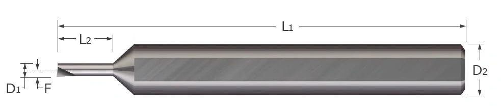
boring bar dimension explanation

Solid carbide boring bars, such as those offered by Micro 100,  have a few standard dimensions that give the tool basic functionality in removing material from an internal bore. These include:

Minimum Bore Diameter (D1): The minimum diameter of a hole for the cutting end of the tool to completely fit inside without making contact at opposing sides

Maximum Bore Depth (L2): Maximum depth that the tool can reach inside a hole without contact from the shank portion

Shank Diameter (D2): Diameter of the portion of the tool in contact with the tool holder

Overall Length (L1): Total length of the tool

Centerline Offset (F): The distance between a tool’s tip and the shank’s centerline axis

Micro100 Continues to Set the Standard for Boring Bars, Shop Today.

Tool Selection

In order to minimize tool deflection and therefore risk of tool failure, it is important to choose a tool with a max bore depth that is only slightly larger than the length it is intended to cut. It is also beneficial to maximize the boring bar and shank diameter as this will increase the rigidity of the tool. This must be balanced with leaving enough room for chips to evacuate. This balance ultimately comes down to the material being bored. A harder material with a lower feed rate and depths of cut may not need as much space for chips to evacuate, but may require a larger and more rigid tool. Conversely, a softer material with more aggressive running parameters will need more room for chip evacuation, but may not require as rigid of a tool.

Geometries

In addition, they have a number of different geometric features in order to adequately handle the three types of forces acting upon the tool during this machining process. During a standard boring operation, the greatest of these forces is tangential, followed by feed (sometimes called axial), and finally radial. Tangential force acts perpendicular to the rake surface and pushes the tool away from the centerline. Feed force does not cause deflection, but pushes back on the tool and acts parallel to the centerline. Radial force pushes the tool towards the center of the bore.

Defining the Geometric Features of a Boring Bar:

Nose Radius: the roundness of a tool’s cutting point

Side Clearance (Radial Clearance): The angle measuring the tilt of the nose relative to the axis parallel to the centerline of the tool

End Clearance (Axial Clearance): The angle measuring the tilt of the end face relative to the axis running perpendicular to the centerline of the tool

Side Rake Angle: The angle measuring the sideways tilt of the side face of the tool

Back Rake Angle: The angle measuring the degree to which the back face is tilted in relation to the centerline of the workpiece

Side Relief Angle: The angle measuring how far the bottom face is tilted away from the workpiece

End Relief Angle: The angle measuring the tilt of the end face relative to the line running perpendicular to the center axis of the tool
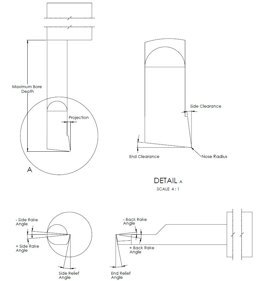
boring bar geometric features

Effects of Geometric Features on Cutting Operations:

Nose Radius: A large nose radius makes more contact with the workpiece, extending the life of the tool and the cutting edge as well as leaving a better finish. However, too large of a radius will lead to chatter as the tool is more exposed to tangential and radial cutting forces.

Another way this feature affects the cutting action is in determining how much of the cutting edge is struck by tangential force. The magnitude of this effect is largely dependent on the feed and depth of cut. Different combinations of depth of cuts and nose angles will result in either shorter or longer lengths of the cutting edge being exposed to the tangential force. The overall effect being the degree of edge wear. If only a small portion of the cutting edge is exposed to a large force it would be worn down faster than if a longer portion of the edge is succumb to the same force. This phenomenon also occurs with the increase and decrease of the end cutting edge angle.

End Cutting Edge Angle: The main purpose of the end cutting angle is for clearance when cutting in the positive Z direction (moving into the hole). This clearance allows the nose radius to be the main point of contact between the tool and the workpiece. Increasing the end cutting edge angle in the positive direction decreases the strength of the tip, but also decreases feed force. This is another situation where balance of tip strength and cutting force reduction must be found. It is also important to note that the angle may need to be changed depending on the type of boring one is performing.

Side Rake Angle: The nose angle is one geometric dimension that determines how much of the cutting edge is hit by tangential force but the side rake angle determines how much that force is redistributed into radial force. A positive rake angle means a lower tangential cutting force as allows for a greater amount of shearing action. However, this angle cannot be too great as it compromises cutting edge integrity by leaving less material for the nose angle and side relief angle.

Back Rake Angle: Sometimes called the top rake angle, the back rake angle for solid carbide boring bars is ground to help control the flow of chips cut on the end portion of the tool. This feature cannot have too sharp of a positive angle as it decreases the tools strength.

Side and End Relief Angles: Like the end cutting edge angle, the main purpose of the side and end relief angles are to provide clearance so that the tools non-cutting portion doesn’t rub against the workpiece. If the angles are too small then there is a risk of abrasion between the tool and the workpiece. This friction leads to increased tool wear, vibration and poor surface finish. The angle measurements will generally be between 0° and 20°.
Boring Bar Geometries Summarized

Boring bars have a few overall dimensions that allow for the boring of a hole without running the tool holder into the workpiece, or breaking the tool instantly upon contact. Solid carbide boring bars have a variety of angles that are combined differently to distribute the 3 types of cutting forces in order to take full advantage of the tool. Maximizing tool performance requires the combination of choosing the right tool along with the appropriate feed rate, depth of cut and RPM. These factors are dependent on the size of the hole, amount of material that needs to be removed, and mechanical properties of the workpiece.
https://www.harveyperformance.com/wp-content/uploads/2019/10/Feature-Image-Boring-Bar-Geometries-IMG.jpg 525 1400 Robert Keever http://www.harveyperformance.com/wp-content/uploads/2018/08/Logo_HarveyPerformanceCompany-4.png Robert Keever2019-10-23 14:03:002022-12-12 08:59:23How Boring Bar Geometries Impact Cutting Operations

The Geometries and Purposes of a Slitting Saw

September 10, 2019/7 Comments/in CNC Machining, Harvey Tool, Machining Techniques, Tool Geometry, Tool Information Guides, Tool Selection/by Harvey Performance Company

When a machinist needs to cut material significantly deeper than wide, a Slitting Saw is an ideal choice to get the job done. These are unique due to their composition and rigidity, which allows it to hold up in a variety of both straightforward and tricky to machine materials.

What is a Slitting Saw?

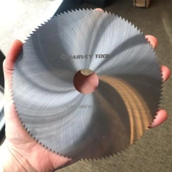
A Slitting Saw is a flat (with or without a dish), circular-shaped tool that has a hole in the middle and teeth on the outer diameter. Used in conjunction with an arbor, this tool is intended for machining purposes that require a large amount of material to be removed within a small diameter, such as slotting or cutoff applications.

Other names include (but are not limited to) Slitting Cutters, Slotting Cutters, Jewelers Saws, and Slitting Knives. Both Jewelers Saws and Slitting Knives are particular types of saws. Jewelers Saws have a high tooth count enabling them to cut tiny, precise features, and Slitting Knives have no teeth at all. On Jewelers Saws, the tooth counts are generally much higher than other types of saws in order to make the cuts as accurate as possible.

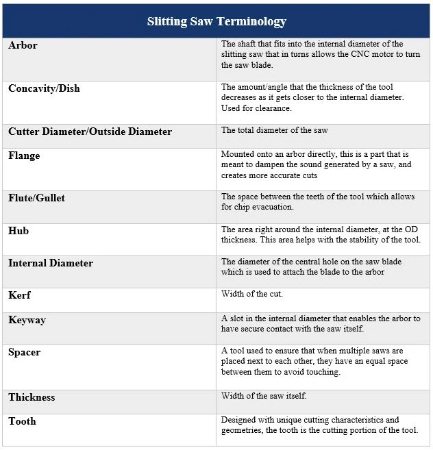
Key Terminology

slitting saw terminology chart

Why Use a Slitting Saw?

These saws are designed for cutting into both ferrous and non-ferrous materials, and by utilizing their unique shape and geometries, they can cut thin slot type features on parts more efficiently than any other machining tool. Non-Ferrous slitting saws have fewer teeth, allowing for aggressively deep depths of cut.

harvey tool slitting saw

Common Applications:

  1. Separating Two Pieces of Material
    1. If an application calls for cutting a piece of material, such as a rod, in half, then a slitting saw will work well to cut the pieces apart while increasing efficiency.
  2. Undercutting Applications
    1. Saws can perform undercutting applications if mounted correctly, which can eliminate the need to remount the workpiece completely.
  3. Slotting into Material
    1. Capable of creating thin slots with a significant depth of cut, Slitting Saws can be just the right tool for the job!

When Not to Use a Slitting Saw

While it may look similar to a stainless steel circular saw blade from a hardware store, this tool should never be used with construction tools such as a table or circular saw.  Brittle saw blades will shatter when used on manual machines, and can cause injury when not used on the proper set up.

In Conclusion

Slitting Saws can be beneficial to a wide variety of machining processes, and it is vital to understand their geometries and purpose before attempting to utilize them in the shop. They are a great tool to have in the shop and can assist with getting jobs done as quickly and efficiently as possible.

https://www.harveyperformance.com/wp-content/uploads/2019/09/Feature-Image-Slitting-Saws-IMG.jpg 525 1400 Harvey Performance Company http://www.harveyperformance.com/wp-content/uploads/2018/08/Logo_HarveyPerformanceCompany-4.png Harvey Performance Company2019-09-10 09:30:532021-11-19 08:37:59The Geometries and Purposes of a Slitting Saw

Machining Precious Metals

July 1, 2019/10 Comments/in How-To's, Machining Techniques, Material Specific/by Robert Keever

Precious metals can be particularly difficult to machine due to their wide range of material properties and high cost if a part has to be scrapped. The following article will introduce these elements and their alloys as well as provide a guide on how to machine them effectively and efficiently.

About the Elements

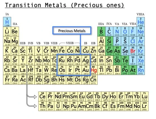
Sometimes called “noble” metals, precious metals consist of eight elements that lie in the middle of the periodic table (seen below in Figure 1). The eight metals are:

  1. Ruthenium (Ru)
  2. Rhodium (Rh)
  3. Palladium (Pd)
  4. Silver (Ag)
  5. Osmium (Os)
  6. Iridium (Ir)
  7. Platinum (Pt)
  8. Gold (Au)

These elements are some of the rarest materials on earth, and can therefore be enormously expensive. Gold and silver can be found in pure nugget form, making them more easily available. However, the other six elements are typically found mixed in the raw ore of the four metals they sit below on the periodic table: Iron (Fe), Cobalt (Co), Nickel (Ni), and Copper (Cu). These elements are a subset of precious metals and are generally called Platinum Group Metals (PGM). Because they are found together in raw ore, this makes mining and extraction difficult, dramatically increasing their cost. Because of their high price tag, machining these materials right the first time is incredibly important to a shop’s efficiency.

periodic table with a box around the 8 precious metals

Figure 1: Periodic table with the 8 precious metals boxed in blue. Image source: clearscience.tumblr.com

Basic Properties and Compositions of Precious Metals

Precious metals have notable material properties as they are characteristically soft, ductile, and oxidation resistant. They are called “noble” metals because of their resistance to most types of chemical and environmental attack. Table 1 lists a few telling material properties of precious metals in their elemental form. For comparison purposes, they are side-by-side with 6061 Al and 4140 Steel. Generally, only gold and silver are used in their purest form as the platinum group metals are alloys that consist mainly of platinum (with a smaller composition of Ru, Rh, Pa, Os, Ir). Precious metals are notable for being extremely dense and having a high melting point, which make them suitable for a variety of applications.

Table 1: Cold-worked Material Properties of Precious Metals, 4140 Steel and 6061 Aluminum 

material properties of precious metals in relation to 6061 and 4140

Common Machining Applications of Precious Metals

Silver and gold have particularly favorable thermal conductivity and electrical resistivity. These values are listed in Table 2, along with CC1000 (annealed copper) and annealed 6061 aluminum, for comparison purposes. Copper is generally used in electrical wiring because of its relatively low electrical resistivity, even though silver would make a better substitute. The obvious reason this isn’t the general convention is the cost of silver vs. copper. That being said, copper is generally plated with gold at electrical contact areas because it tends to oxide after extended use, which lowers its resistivity. As stated before, gold and the other precious metals are known to be resistant to oxidation. This corrosion resistance is the main reason that they are used in cathodic protection systems of the electronics industry.

Table 2: Thermal Conductivity and Electrical Resistivity of Ag, Au, Cu, and Al 

thermal conductivity of silver, gold, copper, and aluminum

Platinum and its respective alloys offer the most amount of applications as it can achieve a number of different mechanical properties while still maintaining the benefits of a precious metal (high melting point, ductility, and oxidation resistance). Table 3 lists platinum and a number of other PGMs each with their own mechanical properties. The variance of these properties depends on the alloying element(s) being added to the platinum, the percentage of alloying metal, and whether or not the material has been cold-worked or annealed. Alloying can significantly increase the tensile strength and hardness of a material while decreasing its ductility at the same time. The ratio of this tensile strength/hardness increase to ductility decrease depends on the metal added as well as how much is added, as seen in Table 3. Generally this depends on the particle size of the element added as well as its natural crystalline structure. Ruthenium and Osmium have a specific crystal structure that has a significant hardening effect when added to platinum. Pt-Os alloys in particular are extremely hard and practically unworkable, which doesn’t yield many real-world applications. However, the addition of the other 4 PGMs to platinum allow for a range of mechanical properties with various usages.

Table 3: PGM material properties (Note: the hardness and tensile strength are cold worked values) 

pgm material properties

Platinum and its alloys are biocompatible, giving them the ability to be placed in the human body for long periods of time without causing adverse reactions or poisoning. Therefore, medical devices including heart muscle screw fixations, stents, and marker bands for angioplasty devices are made from platinum and its alloys. Gold and palladium are also commonly used in dental applications.

Pt-Ir alloys are noticeably harder and stronger than any of the other alloys and make excellent heads for spark plugs in the automobile industry. Rhodium is sometimes added to Pt-Ir alloys to make the material less springy (as they are used as medical spring wire) while also increasing its workability. Pt and Pt-Rh wire pairs are extremely effective at measuring temperatures and are therefore used in thermocouples.

Machining Precious Metals

The two parameters that have the most effect when machining are hardness and percent elongation. Hardness is well-known by machinists and engineers across the manufacturing industry as it indicates a material’s resistance to deformation or cutting. Percent elongation is a measurement used to quantify material ductility. It indicates to a designer the degree to which a structure will deform plastically (permanently) before fracture. For example, a ductile plastic such as ultrahigh molecular weight polyethylene (UHMWPE) has a percent elongation of 350-525%, while a more brittle material such as oil-quenched and tempered cast iron (grade 120-90-02) has a percent elongation of about 2%. Therefore, the greater the percent elongation, the greater the material’s “gumminess.” Gummy materials are prone to built-up edge and have a tendency to produce long stringy chips.

Tools for Precious Metals

Material ductility makes a sharp cutting tool essential for cutting precious metals. Variable Helix for Aluminum Alloy tools can be used for the softer materials such as pure gold, silver, and platinum.

variable helix square aluminum end mill from harvey tool

Figure 2: Variable Helix Square End Mill for Aluminum Alloys

Higher hardness materials still require a sharp cutting edge. Therefore, one’s best option is to invest in a PCD Diamond tool. The PCD wafer has the ability to cut extremely hard materials while maintaining a sharp cutting edge for a relatively long period of time, compared to standard HSS and carbide cutting edges.

harvey tool pcd diamond square end mill

Figure 3: PCD Diamond Square End Mill

Speeds and Feeds charts:

speeds and feeds chart for precious metals

Figure 4: Speeds and Feeds for precious metals when using a Square Non-ferrous, 3x LOC

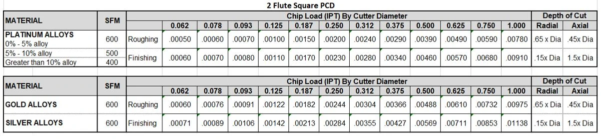
speeds and feeds chart for precious metals with a pcd end mill

Figure 5: Speeds and Feeds for precious metals when using a 2-Flute Square PCD end mill

https://www.harveyperformance.com/wp-content/uploads/2020/07/Machining-Precious-Metals.jpg 600 1599 Robert Keever http://www.harveyperformance.com/wp-content/uploads/2018/08/Logo_HarveyPerformanceCompany-4.png Robert Keever2019-07-01 12:58:512023-10-24 10:50:51Machining Precious Metals

An Introduction to Reamers & CNC Reaming

June 10, 2019/3 Comments/in Drilling & Holemaking, Harvey Tool, Machining Techniques, Tool Information Guides, Tool Selection/by Harvey Performance Company

Most machinists are familiar with CNC drilling, but did you know that the common practice for holemaking is to always use a reamer? When done correctly, reaming can be a fast and highly accurate operation that results in precision holes.

Critical Reamer Geometries

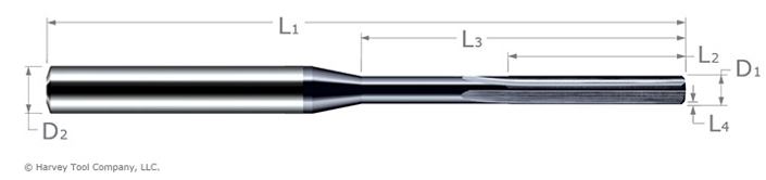
harvey tool miniature straight flute reamer with dimension callouts
Harvey Tool Miniature Reamer

By examining a Harvey Tool Miniature Reamer and its critical dimensions, we can better understand the functionality of this useful tool. In the above image of a straight flute reamer, D1 references the reamer diameter, the specific size intended for your hole; and D2 points to the shank diameter. At Harvey Tool, reamer shanks are oversized to help maintain tool strength, stiffness, and accuracy. Shanks also have an h6 tolerance, which is crucial for high precision tool holders, such as heat shrink collets. Other critical dimensions of a reamer include its overall length (L1), margin length (L2), overall reach (L3), and chamfer length (L4).

Harvey Tool also offers Miniature Reamers – Right Hand Spiral. This tool is designed to leave a superior part finish and help with chip evacuation in blind hole applications.

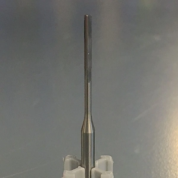
straight flute miniature reamer

The Functions of Miniature Reamers

Reamers Provide Precision – As mentioned earlier, reamers are great for machining precision hole diameters. To use a reamer properly, you must first have a pre-drilled hole that’s between 90% and 94% of the final hole diameter. For example, if you need a finished a hole of .220″, your predrilled hole should be somewhere between .1980″ and .2068″. This allows the tool to take enough material off to leave a great finish, but does not overwork it, potentially causing damage. The tolerance for uncoated reamers is +.0000″/-.0002″, while the tolerance for AlTiN coating is +.0002″/-.0000″. These tolerances provide you the peace of mind of knowing that your hole will meet exact specifications.

Achieve a Quality CNC Finish – When a high surface finish is required of a hole, reamers should always be used to reach the desired tolerance. Both the pre-drilled hole and the tool’s margin help to keep the reamer centered while cutting, leading to a better finish.

miniature reamer and end mill next to a penny

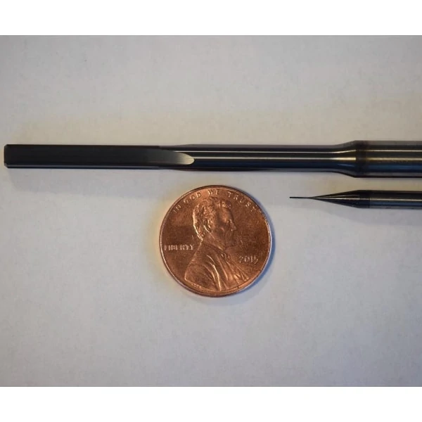
Minimize Machining Production Runs – For machine shops, consistency is a priority. This is especially true in production runs. The last thing a machinist wants to see is an oversized hole on a part they have already preformed many operations on. Remember, reamers have the benefit of offering consistent hole size, preventing an out of tolerance finish. These consistent holes lead to valuable time savings and reduced scrap costs.

CNC Machining Exotic Alloys: When machining Inconel, titanium, and other high-cost materials, reaming your hole is important to ensure that the desired finish specification is met. With reamers, a machinists can better predict tool life, leading to a better finished product and less scrap ratios. It is important to note that Harvey Tool reamers are offered AlTiN coated and fully stocked in every .0005” increment from .0080” to .0640”.

https://www.harveyperformance.com/wp-content/uploads/2019/06/Feature-Image-Intro-to-Reamers-IMG.jpg 525 1400 Harvey Performance Company http://www.harveyperformance.com/wp-content/uploads/2018/08/Logo_HarveyPerformanceCompany-4.png Harvey Performance Company2019-06-10 10:57:532023-10-24 10:51:30An Introduction to Reamers & CNC Reaming

Confidently Select Your Next Thread Mill

January 10, 2019/0 Comments/in Drilling & Holemaking, Harvey Tool, Machining Techniques, Thread Milling, Tool Information Guides, Tool Selection/by Ben Holm

Do you know the key differences between a Single Form Thread Mill and a Multi-Form version? Do you know which tooling option is best for your job? This blog post examines how several factors, including the tool’s form and max depth of thread, are important to ultimately making the appropriate Harvey Tool decision.

Thread Mill Product Offering

Single Form

The single form thread mill is the most versatile threading solution Harvey Tool offers. These tools are ground to a sharp point and are capable of milling 60° thread styles, such as UN, metric, and NPT threads. With over 14 UN and 10 Metric sized tools, Harvey Tool’s single form selections allow machinists the opportunity to machine many different types of threads.

single form harvey tool thread mill

Harvey Performance Company, LLC.

Single Form Thread Mills for Hardened Steels

Similar to the standard single form, Harvey Tool’s thread mills for hardened steels offer machinists a quality option when dealing with hardened steels from 46-68 Rc. The following unique geometries helps this tool machine tough alloys:

  1. Ground Flat – Instead of a sharp point these tools have a ground flat to help ensure long tool life.
  2. Eccentric Relief – Gives the cutting edges extra strength for the high feeds at relatively low RPMs required for harder materials.
  3. AlTiN Nano Coating – Allows for superior heat resistance.

single form thread mill for hardened steels

Harvey Performance Company, LLC.

A key difference between the standard Single Form and the Single Form for Hardened Steels is that the tools for hardened steels are actually only capable of milling 83% of the actual thread depth. At first, this may seem detrimental to your operation. However, according to the Machinery’s Handbook 29th Edition, “Tests have shown that any increase in the percentage of full thread over 60% does not significantly increase the strength of the thread. Often, a 55% to 60% thread is satisfactory, although 75% threads are commonly used to provide an extra margin of safety.” With the ability to preserve tool life and effectively perform thread components, Harvey Tool’s single form thread mills for hardened steels are a natural choice when tackling a hardened material.

Tri-Form

Tri-Forms are designed for difficult-to-machine materials. The tri-form design reduces tool pressure and deflection, which results in more accurate threading. Its left-hand cut, left-hand spiral design allows it to climb mill from the top of the thread to the bottom.

tri form thread mill from harvey tool

Harvey Performance Company, LLC.

Multi-Form

Our multi-form thread mills are offered in styles such as UN, NPT, and Metric. Multi-Form tools are optimized to produce a full thread in single helical interpolation. Additionally, they allow a machinist to quickly turn around production-style jobs.

multi-form thread mill

Harvey Performance Company, LLC.

Coolant-Through Multi Form Thread Mills

Coolant-Through Multi Form Thread Mills are the perfect tool for when a job calls for thread milling in a blind hole. The coolant through ability of the tool produces superior chip evacuation. These tools also improve coolant flow to the workpiece – delivering it directly from the tip of the tool – for decreased friction and high cutting speeds.

coolant through multi form thread mill

Harvey Performance Company, LLC.

Long Flute

These tools are great when a job calls for a deep thread, due to their long flute. Long Flutes also have a large cutter diameter and core, which provides the tool with improved tool strength and stability.

long flute harvey tool thread mill

Harvey Performance Company, LLC.

N.P.T. Multi-Form

While it may seem obvious, N.P.T. Multi-Form Thread Mills are perfect for milling NPT threads. NPT threads are great for when a part requires a full seal, different from traditional threads that hold pieces together without the water-tight seal.

npt thread mill from harvey tool

Harvey Performance Company, LLC.

https://www.harveyperformance.com/wp-content/uploads/2019/01/Feature-Image-Selecting-Thread-Mill-IMG.jpg 525 1400 Ben Holm http://www.harveyperformance.com/wp-content/uploads/2018/08/Logo_HarveyPerformanceCompany-4.png Ben Holm2019-01-10 01:44:532024-04-30 09:42:20Confidently Select Your Next Thread Mill

How to Extend the Life of Your End Mill

December 5, 2018/2 Comments/in CNC Machining, High Efficiency Milling, How-To's, Machining Techniques, Milling, Quick Tips/by Harvey Performance Company

Breaking and damaging an end mill is oftentimes an avoidable mistake that can be extremely costly for a machine shop. To save time, money, and your end mill it is important to learn some simple tips and tricks to extend tool life.

Properly Prepare Before the Tool Selection Process

The first step of any machining job is selecting the correct end mill for your material and application. However, this doesn’t mean that there should not be an adequate amount of legwork done beforehand to ensure the right decision on a tool is being made. Harvey Tool, Helical Solutions, Titan USA, and Corehog have thousands of different tools for different operations – a vast selection which, if unprepared – can easily result in selecting a tool that’s not the best for your job. To start your preparation, answer the 5 Questions to Ask Before Selecting an End Mill to help you quickly narrow down your selection and better understand the perfect tool you require.

Understand Your Tooling Requirements

It’s important to understand not only what your tool needs, but also general best practices to avoid common machining mishaps. For instance, it is important to use a tool with a length of cut only as long as needed, as the longer a tools length of cut is, the greater the chance of deflection or tool bending, which can decrease its effective life.

end mill being fed coolant cutting into a workpiece to extend tool life

Another factor to consider is the coating composition on a tool. Harvey Tool and Helical Solutions offer many varieties of tool coatings for different materials. Some coatings increase lubricity, slowing tool wear, while others increase the hardness and abrasion resistance of the tool. Not all coatings increase your tool’s life in every material, however. Be wary of coatings that don’t perform well in your part’s material – such as the use of AlTiN coating in Aluminum (Both coating and material are aluminum-based and have a high affinity for each other, which can cause built-up edge and result in chip evacuation problems).

Consider Variable Helix & Pitch Geometry

A feature on many of our high performance end mills is variable helix or variable pitch geometry, which have differently-spaced flutes. As the tool cuts, there are different time intervals between the cutting edges contacting the workpiece, rather than simultaneously on each rotation. The varying time intervals minimizes chatter by reducing harmonics, increasing tool life and producing better results.

Ensure an Effective Tool Holding Strategy

Another factor in prolonging tool life is proper tool holding. A poor tool holding strategy can cause runout, pullout, and scrapped parts. Generally, the most secure connection has more points of contact between the tool holder and tool shank. Hydraulic and Shrink Fit Tool Holders provide increased performance over other tightening methods.

three different end mills in tool holders

Helical also offers shank modifications to all stocked standards and special quotes, such as the ToughGRIP Shank, which provides added friction between the holder and the shank of the tool for a more secure grip; and the Haimer Safe-Lock™, which has grooves on the shank of the tool to help lock it into place in a tool holder.

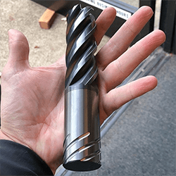
massive helical end mill in machinists hand

Trust Your Running Parameters, and their Source

After selecting the correct end mill for your job, the next step is to run the tool at the proper speeds and feeds.

Run at the Correct Speed

Understanding the ideal speed to run your machine is key to prolonging tool life. If you run your tool too fast, it can cause suboptimal chip size, ineffective chip evacuation, or even total tool failure. Adversely, running your tool too slowly can result in deflection, bad finish, or decreased metal removal rates.

Push at the Best Feed Rate

Another critical parameter of speeds and feeds is finding the best possible feed rate for your job, for sake of both tool life and achieving maximum shop efficiency. Pushing your tool too aggressively can result in breakage, but being too conservative can lead to recutting chips and excess heat generation, accelerating tool wear.

Use Parameters from Your Tooling Manufacturer

A manufacturer’s speeds and feeds calculations take into account every tool dimension, even those not called out in a catalog and readily available to machinists. Because of this, it’s best to rely on running parameters from tooling manufacturers. Harvey Tool offers speeds and feeds charts for every one of its more than 21,000 tools featured in its catalog, helping machinists to confidently run their tool the first time.

Harvey Performance Company offers the Machining Advisor Pro application, a free, cutting-edge resource that generates custom running parameters for optimized machining with all of Helical Solutions’ and Harvey Tool’s products.

machining advisor pro graphic for pc, laptops, and other devices

Opt for the Right Milling Strategy: Climb vs Conventional

There are two ways to cut material when milling: Climb Milling and Conventional Milling. In conventional milling, the cutter rotates against the feed. In this method, chips will start at theoretical zero and increase in size. Conventional milling is usually recommended for tools with higher toughness, or for breaking through case hardened materials.

In Climb Milling, the cutter rotates with the feed. Here, the chips start at maximum width and decrease, causing the heat generated to transfer into the chip instead of being left in the tool or work piece. Climb milling also produces a cleaner shear plane, causing less rubbing, decreasing heat, and improving tool life. When climb milling, chips will be removed behind the cutter, reducing your chances of recutting.

Utilize High Efficiency Milling

High Efficiency Milling (HEM), is a roughing technique that uses the theory of chip thinning by applying a smaller radial depth of cut (RDOC) and a larger axial depth of cut (ADOC). The parameters for HEM are similar to that of finishing, but with increased speeds and feeds, allowing for higher material removal rates (MRR). HEM utilizes the full length of cut instead of just a portion of the cutter, allowing heat to be distributed across the cutting edge, maximizing tool life and productivity. This reduces the possibility of accelerated tool wear and breakage.

Decide On Coolant Usage & Delivery

Coolant can be an extremely effective way to protect your tool from premature wear and possible tool breakage. There are many different types of coolant and methods of delivery to your tool. Coolant can come in the form of compressed air, water-based, straight oil-based, soluble oil-based, synthetic or semi-synthetic. It can be delivered as mist, flood, high pressure or minimum quantity lubricant.

Appropriate coolant type and delivery vary depending on your application and tool. For example, using a high pressure coolant with miniature tooling can lead to tool breakage due to the fragile nature of extremely small tools. In applications of materials that are soft and gummy, flood coolant washes away the long stringy chips to help avoid recutting and built-up edge, preventing extra tool wear.

Extend Your Tool’s Life

The ability to maximize tool life saves you time, money and headaches. To get the best possible outcome from your tool, you first need to be sure you’re using the best tool for your job. Once you find your tool, ensure that your speeds and feeds are accurate and are from your tooling manufacturer. Nobody knows the tools better than they do. Finally, think about how to run your tool: the rotation of your cutter, whether utilizing an HEM approach is best, and how to introduce coolant to your job.

https://www.harveyperformance.com/wp-content/uploads/2018/12/Featured-Image-Life-of-End-Mill-IMG.jpg 525 1400 Harvey Performance Company http://www.harveyperformance.com/wp-content/uploads/2018/08/Logo_HarveyPerformanceCompany-4.png Harvey Performance Company2018-12-05 11:28:212023-10-24 09:56:33How to Extend the Life of Your End Mill

Main Differences Between Engravers & Marking Cutters

November 16, 2018/13 Comments/in Harvey Tool, Machining Techniques, Specialty Tools, Tool Geometry, Tool Information Guides/by Harvey Performance Company

Understanding the Distinctions

While similar on the surface, Half-round Engraving Cutters and Marking Cutters are actually very different. Both tools are unique in the geometries they possess, the benefits they offer, and the specific purposes they’re used for. Below are the key differences that all machinists must know, as the engraving on a part is often a critical step in the machining process.

harvey tool marking cutters ad

Engravers & Marking Cutters Serve Different Purposes

All Marking Cutters are Engraving Cutters, but not all Engraving Cutters are Marking Cutters. This is because Marking Cutters are a “type” of engraving tool. By virtue of their sturdier geometry, these tools are suited for applications requiring repetition such as the engraving of serial numbers onto parts. Harvey Tool has been able to customize specific tool geometries for ferrous and non-ferrous applications, offering Marking Cutters for material specific purposes.

harvey tool marking cutter

Engraving Cutters, on the other hand, are meant for finer detailed applications that require intricate designs such as engraving a wedding band or a complex brand design.

harvey tool doubled ended engraving cutter

These Tools Have Unique Geometry Features

Historically, Engraving Cutters have been made as a half round style tool. This tool allows for a true point, which is better for fine detail, but can easily break if not run correctly. Because of this, these tools have performed well in softer materials such as aluminum and wood, especially for jobs that require an artistic engraving with fine detail.

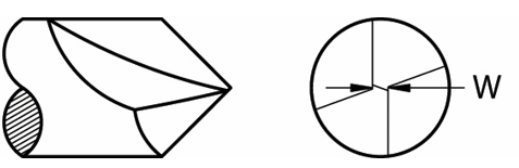
Marking cutters are not as widely seen throughout the industry, however. These tools hold up in harder-to-machine materials exceedingly well. Marking Cutters are a form of Engraving Cutter that contain 2 flutes and a web at the tip, meaning that the tool has a stronger tip and is less susceptible to breakage.

tip details of an engraver versus marking cutter

While these tools do not contain a true point (due to their web), they do feature shear flutes for better cutting action and the ability to evacuate chips easier when compared to a half-round engraver.

Harvey Tool Product Offering

Harvey Tool offers a wide variety of both Engraving Cutters and Marking Cutters. Choose from a selection of pointed, double-ended, tip radius, and tipped-off Engraving Cutter styles in 15 included angles ranging from 10° to 120°.

types of cnc engraver tips, pointed, radiused, and tipped-off

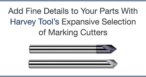
Marking Cutters are fully stocked in tip radius or tipped-off options, and are designed specifically for either ferrous or non-ferrous materials. They are are offered in included angles from 20° to 120°.

While Engraving Cutters are offered uncoated or in AlTiN, AlTiN Nano, or Amorphous Diamond coatings, Marking Cutters are fully stocked in uncoated, AlTiN, or TiB2 coated styles.

Add Fine Details to Your Parts With Harvey Tool’s Expansive Selection of Marking Cutters

Choosing the Right Tool

While both Engraving Cutters and Marking Cutters can accomplish similar tasks, each tool has its own advantages and purpose. Selecting the correct tool is based largely on preference and applicability to the job at hand. Factors that could impact your selection would be final Depth of Cut, Width of Cut, the angle needing to be achieved, and the desired detail of the engraving.

https://www.harveyperformance.com/wp-content/uploads/2018/11/Feature-Image-Engravers-Marking-Cutters-IMG.jpg 525 1400 Harvey Performance Company http://www.harveyperformance.com/wp-content/uploads/2018/08/Logo_HarveyPerformanceCompany-4.png Harvey Performance Company2018-11-16 08:57:532024-04-12 11:55:11Main Differences Between Engravers & Marking Cutters

Effective Ways to Reduce Heat Generation

October 25, 2018/1 Comment/in High Efficiency Milling, How-To's, Machining Techniques, Quick Tips/by Harvey Performance Company

Any cutting tool application will generate heat, but knowing how to counteract it will improve the life of your tool. Heat can be good and doesn’t need to totally be avoided, but controlling heat will help prolong your tool life. Sometimes, an overheating tool or workpiece is easy to spot due to smoke or deformation. Other times, the signs are not as obvious. Taking every precaution possible to redirect heat will prolong your tool’s usable life, avoid scrapped parts, and will result in significant cost savings.

Reduce Heat Generation with HEM Tool Paths

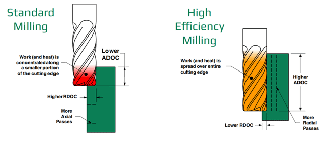
High Efficiency Milling (HEM), is one way a machinist should explore to manage heat generation during machining. HEM is a roughing technique that uses the theory of chip thinning by applying a smaller radial depth of cut (RDOC) and a larger axial depth of cut (ADOC). HEM uses RDOC and ADOC similar to finishing operations but increases speeds and feeds, resulting in greater material removal rates (MRR). This technique is usually used for removing large amounts of material in roughing and pocketing applications. HEM utilizes the full length of cut and more effectively uses the full potential of the tool, optimizing tool life and productivity. You will need to take more radial passes on your workpiece, but using HEM will evenly spread heat across the whole cutting edge of your tool, instead of building heat along one small portion, reducing the possibility of tool failure and breakage.

heat generation in standard versus hem milling and their associated depths of cut

Chip Thinning Awareness

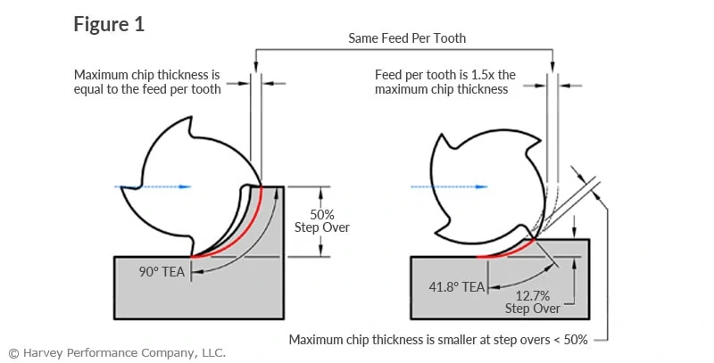
Chip thinning occurs when tool paths include varying radial depths of cut, and relates to chip thickness and feed per tooth. HEM is based off of the principal of chip thinning. However, if not properly executed, chip thinning can cause a lot of heat generation. When performing HEM, you effectively reduce your stepover and increase your speeds and feeds to run your machine at high rates. But if your machine isn’t capable of running high enough speeds and feeds, or you do not adjust accordingly to your reduced stepover, trouble will occur in the form of rubbing between the material and tool. Rubbing creates friction and mass amounts of heat which can cause your material to deform and your tool to overheat. Chip thinning can be good when used correctly in HEM, but if you fall below the line of reduced stepover without higher speeds and feeds, you will cause rubbing and tool failure. Because of this, it’s always important to be aware of your chips during machining. Understanding chip thinning is paramount to success in in machining.

infographic showcasing chip thinning in relation to step over

Consider Climb Milling

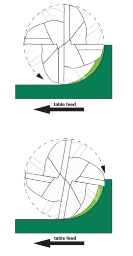
There are two ways to cut materials when milling: conventional milling and climb milling. The difference between the two is the relationship of the rotation of the cutter to the direction of feed. In climb milling, the cutter rotates with the feed, as opposed to conventional milling where the cutter rotates against the feed.

When conventional milling, chips start at theoretical zero and increase in size, causing rubbing and potentially work hardening. For this reason, it’s usually recommended for tools with higher toughness or for breaking through case hardened materials.

In climb milling, the chip starts at maximum width and decreases, causing the heat generated to transfer into the chip instead of the tool or workpiece. When going from max width to theoretical zero, heat will be transferred to the chip and pushed away from the workpiece, reducing the possibility of damage to the workpiece. Climb milling also produces a cleaner shear plane which will cause less tool rubbing, decreasing heat and improving tool life. When climb milling, chips are removed behind the cutter, reducing your chances of re-cutting. climb milling effectively reduces heat generated to the tool and workpiece by transferring heat into the chip, reducing rubbing and by reducing your chances of re-cutting chips.

infographic showing climb versus conventional milling in feed path and end mill direction

Utilize Proper Coolant Methods

If used properly, coolant can be an extremely effective way to keep your tool from excessive heat generation. There are many different types of coolant and different ways coolant can be delivered to your tool. Coolant can be compressed air, water-based, straight oil-based, soluble oil-based, synthetic or semi-synthetic. It can be delivered as mist, flood, high pressure or minimum quantity lubricant.

Different applications and tools require different types and delivery of coolant, as using the wrong delivery or type could lead to part or tool damage. For instance, using high pressure coolant with miniature tooling could lead to tool breakage. In materials where chip evacuation is a major pain point such as aluminum, coolant is often used to flush chips away from the workpiece, rather than for heat moderation. When cutting material that produces long, stringy chips without coolant, you run the risk of creating built-up edge from the chips evacuating improperly. Using coolant will allow those chips to slide out of your toolpath easily, avoiding the chance of re-cutting and causing tool failure. In materials like titanium that don’t transfer heat well, proper coolant usage can prevent the material from overheating. With certain materials, however, thermal shock becomes an issue. This is when coolant is delivered to a very hot material and decreases its temperature rapidly, impacting the material’s properties. Coolant can be expensive and wasteful if not necessary for the application, so it’s important to always make sure you know the proper ways to use coolant before starting a job.

Importance of Controlling Heat Generation

Heat can be a tool’s worst nightmare if you do not know how to control it. High efficiency milling will distribute heat throughout the whole tool instead of one small portion, making it less likely for your tool to overheat and fail. By keeping RDOC constant throughout your toolpath, you will decrease the chances of rubbing, a common cause of heat generation. Climb milling is the most effective way to transfer heat into the chip, as it will reduce rubbing and lessen the chance of re-chipping. This will effectively prolong tool life. Coolant is another method for keeping temperatures moderated, but should be used with caution as the type of coolant delivery and certain material properties can impact its effectiveness.

https://www.harveyperformance.com/wp-content/uploads/2018/10/Feature-Image-Reduce-Heat-Generation-IMG.jpg 525 1400 Harvey Performance Company http://www.harveyperformance.com/wp-content/uploads/2018/08/Logo_HarveyPerformanceCompany-4.png Harvey Performance Company2018-10-25 11:26:402025-02-12 09:59:35Effective Ways to Reduce Heat Generation

Workholding Styles & Considerations

October 18, 2018/0 Comments/in CNC Machining, Getting Started, Machining 101, Machining Techniques, Milling, Tech Tips/by Robert Keever

Machinists have a number of variables to consider when setting up devices for a machining operation. When it comes to cnc workholding, there are some major differences between holding a loosely toleranced duplicate part with a 10-minute cycle time and holding a tightly toleranced specialized part with a 10-hour cycle time. Determining which method works best for your machining job is essential to maintaining an efficient operation.

CNC Workholding Devices

Ideal workholding devices have easily repeatable setups. For this reason, some machines have standard workholding devices. Vises are generally used with milling machines while chucks or collets are used when running a lathe machine. Sometimes, a part may need a customized cnc workholding setup in order to secure the piece properly during machining. Fixtures and jigs are examples of customized devices.

Fixtures and Jigs

A jig is a work holding device that holds, supports and locates a workpiece and guides the cutting tool into a specific operation (usually through the use of one or more bushings). A fixture is essentially the same type of device, but the main difference is that it does not guide the cutting tool into a specified operation. Fixtures are typically used in milling operations while jigs are generally used in drilling, reaming, tapping and boring. Jigs and fixtures are more precise relative to standard cnc workholding devices, which leads to tighter tolerances. They can also be indexable, allowing them to control the cutting tool movement as well as workpiece movement. Both jigs and fixtures are made up of the same basic components: fixture bodies, locators, supports, and clamps.

The 4 Fixture Bodies

There are 4 basic types of fixture bodies: faceplates, baseplates, angle plates, and tombstones.

Faceplates: Typically used in lathe operations, where components are secured to the faceplate and then mounted onto the spindle.

Baseplates: Common in milling and drilling operations and are mounted to the worktable.

Angle plates: Two plates perpendicular to each other but some are adjustable or customized to change the angle of the workpiece.
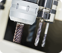
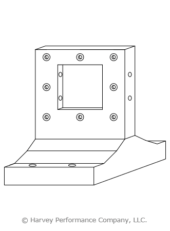
Tombstones: Large vertically oriented rectangular fixtures that orients a workpiece perpendicular to the worktable. Tombstones also have two sides to accommodate multiple parts.

cnc tombstone work holding fixture body

Locators

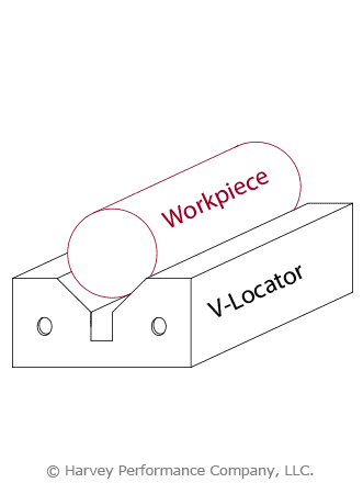
Locators are characterized by four criteria: assembled, integral, fixed, and adjustable. Assembled locators, can be attached and removed from the fixture, which is contrary to integral locators that are built into the fixture. Fixed locators allow for no moving components, while adjustable locators permit movement through the use of threads and/or springs, and can adjust to a workpiece’s size. These can be combined to provide the appropriate rigidity-assembly convenience ratio. For example, a V-locator fixture is the combination of assembled and fixed locators. It can be secured to a fixture but has no moving components.

cnc workholding showcasing a workpiece in v-locator

Supports

Supports do exactly what their name suggests, they support the workpiece during the machining process to avoid workpiece deformation. These components can double as locators and also come fixed, adjustable and integral, or assembled. Generally, supports are placed under the workpiece during manufacturing but this also depends on the geometry of the workpiece, the machine being operated and where the cutting tool will make contact. Supports can come in different shapes and sizes. For example, rest buttons are smaller support components used in series either from underneath the workpiece or from the sides. Concurrently, parallel supports are placed on either side of the part to provide general support.

cnc material support with parallel supports and rest buttons

Clamps

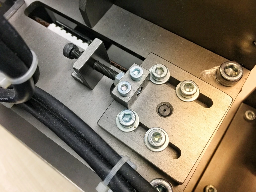
Clamps are devices used for strengthening or holding things together, and come in different shapes, sizes and strengths. Vises and chucks have movable jaws and are considered standard clamps. One atypical example is the toggle clamp, which has a pivot pin that acts as a fulcrum for a lever system. One of the more convenient types is a power clamping system. There are two type of power clamping methods: hydraulic and pneumatic.

cnc workholding clamps

Example of a standard fixture setup.

Hydraulic Workholding Systems

Hydraulic Systems create a gripping force by attaining power from compressing a liquid. This type of power clamp is generally used with larger workpieces as it usually takes up less space relative to pneumatic clamps.

Pneumatic clamps

Pneumatic clamps attain their gripping force from the power created by a compressed gas (usually air). These systems are generally bulkier and are used for smaller workpieces that require less room on the worktable. Power clamping offers a few advantages over conventional clamping. First, these systems can be activated and deactivated quickly to save on changeover time. Second, they place uniform pressure on the part, which help prevent errors and deformation. A significant disadvantage they pose is the cost of a system but this can be quickly offset by production time saved.

Key Guidelines to Follow

Lastly, there are a few guidelines to follow when choosing the appropriate CNC workholding fixture or jig setup.

Ensure Proper Tolerancing

The tolerances of the workholding device being used should be 20%-50% tighter than those of the workpiece.
Utilize Acceptable Locating & Supporting Pieces

Locating and supporting pieces should be made of a hardened material to prevent wear and allow for several uses without the workpieces they support falling out of tolerance. Supports and locators should also be standardized so that they can be easily replaced.

Place Workholding Clamps in Correct Locations

Clamps should be placed above the locations of supports to allow the force of the clamp to pass into the support without deforming the workpiece. Clamps, locators and supports should also be placed to distribute cutting forces as evenly as possible throughout the part. The setup should allow for easy clamping and not require much change over time
Maximize Machining Flexibility

The design of the fixture or jigs should maximize the amount of operations that can be performed in one orientation. During the machining operation, the setup should be rigid and stable.

Bottom Line

Workholding can be accomplished in a number of different ways and accomplish the same task of successfully gripping a part during a machining operation with the end result being in tolerance. The quality of this workholding may differ greatly as some setups will be more efficient than others. For example, there is no reason to create an elaborate jig for creating a small slot down the center of a rectangular brick of aluminum; a vise grip would work just fine. Maximizing the efficiency and effectiveness of an operators’ cnc workholding setup will boost productivity by saving on changeover, time as well as cost of scrapped, out of tolerance parts.
https://www.harveyperformance.com/wp-content/uploads/2018/10/Featured-Image-Workholding-Styles-IMG.jpg 525 1400 Robert Keever http://www.harveyperformance.com/wp-content/uploads/2018/08/Logo_HarveyPerformanceCompany-4.png Robert Keever2018-10-18 08:44:202023-10-24 10:41:29Workholding Styles & Considerations

Experience the Benefits of Staggered Tooth Keyseats

September 19, 2018/0 Comments/in CNC Machining, Tool Information Guides, Tool Selection/by Harvey Performance Company

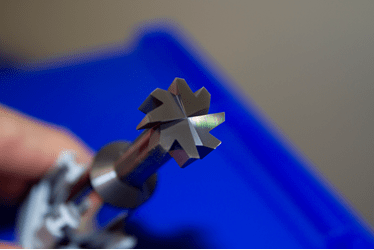
Keyseat Cutters, also known as Woodruff Cutters, Keyway Cutters, and T-Slot Cutters, are commonly used in machine shops. Many machinists opt to use this tool to put a slot on the side of a part in an efficient manner, rather than rotating the workpiece and using a traditional end mill. A Staggered Tooth Keyseat Cutter has alternating right-hand and left hand shear flutes and is right-hand cut, whereas a traditional keyseat cutter has all straight flutes and is right-hand cut. Simply, the unique geometry of a Staggered Tooth Keyseat Cutter gives the tool its own set of advantages including the ability to index within the slot, increase feed rates, and achieve better part finish.

face of a staggered tooth keyseat cutter

Three Key Benefits

Indexing

The alternating right-and-left-hand flutes of a Harvey Tool Staggered Tooth Keyseat Cutters are relieved on both sides of its head, meaning that it allows for both end cutting and back cutting. This adds to the versatility of the staggered tooth keyseat cutter, where one singular tool can be indexed axially within a slot to expand the slot to a specific uncommon dimension. This can save space in a machinist’s magazine and reduce machine time by eliminating the need to swap to a new tool.

Increased Feed Rates

Due to the unique geometry of a Staggered Tooth Keyseat Cutter, chips evacuate efficiently and at a faster rate than that of a Straight Flute Keyseat Cutter. The unique flutes of Staggered Tooth Keyseat Cutters are a combination of right-and-left-hand shear flutes, but both types are right-hand cutting. This results in the tool’s teeth alternating between upcut and downcut. Chip packing and chip recutting is less of a concern with running this tool, and results in increased chip loads compared to that of a standard keyseat with the same number of flutes. Because of this, the tool can account for chiploads of about 10% higher than the norm, resulting in heightened feed rates and shorter cycle times overall.

Better Part Finish

Staggered Tooth Keyseat Cutters have “teeth”, or flutes, that are ground at an angle creating a shear flute geometry. This geometry minimizes chip recutting, chip dragging and reduces the force needed to cut into the material. Chip recutting and dragging are minimized because chips are evacuated out of the top and bottom of the head on the side of the cutter that is not engaged in the material. Shear flutes also reduce vibrations that can lead to chatter and poor finish. By minimizing cutting forces, vibration, and chatter, a machinist can expect a better part finish.

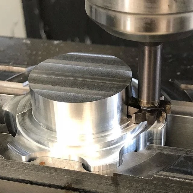
staggered tooth keyseat cutter working in a cnc machine

Image courtesy of @edc_machining

Staggered Tooth Keyseat Cutter Diverse Product Offering

On top of the higher performance one will experience when using the Stagger Tooth Keyseats, there are also multiple options available with various combinations to suit multiple machining needs. This style is offered in a square, square reduced shank and corner radius profile which helps if a fillet or sharp corner is needed. The square and corner radius tools are offered in diameters ranging from 1/8” to 5/8”, and the square reduced shank tool is offered in diameteres ranging from 3/4″ to 1-1/2″. The increased diameter comes with an increase of radial depth of cut, allowing deeper slots to be achievable. Within the most popular cutter diameters, ¼”, 3/8”, and ½” there are also deep slotting options with even greater radial depth of cuts for increased slot depths. On top of the diameters and radii, there are also multiple cutter widths to choose from to create different slots in one go. Finally, an uncoated and AlTiN coatings are available to further increase tool life and performance depending on the material that is being cut.

Opt for a Smoother Operation

A Staggered Tooth Keyseat Cutter adds versatility to a tool magazine. It can be indexed axially to expand slots to make multiple widths, allowing machinists to progress operations in a more efficient manner where tool changes are not required. Further, this tool will help to reduce harmonics and chatter, as well as minimize recutting. This works to create a smoother operation with less force on the cutter, resulting in a better finish compared to a Standard Keyseat Cutter.

For more information on Harvey Tool Staggered Tooth Keyseat Cutters and its applications, visit Harvey Tool’s Keyseat Cutter page.

https://www.harveyperformance.com/wp-content/uploads/2018/09/Featured-Image-Benefits-of-Staggered-Tooth-Keyseats-IMG.jpg 525 1400 Harvey Performance Company http://www.harveyperformance.com/wp-content/uploads/2018/08/Logo_HarveyPerformanceCompany-4.png Harvey Performance Company2018-09-19 10:35:552023-10-24 10:45:04Experience the Benefits of Staggered Tooth Keyseats
Page 6 of 10«‹45678›»
BLOG HOME

Search In the Loupe

More results...

Browse by Topic

How-To’s
Technical Tips
Tools In Action
Featured Customers
Tool Guides

Free Drilling Guidebook

DOWNLOAD

Recent Posts

  • Machining a Complex Part with Harvey Tool
  • Drill Substrate Guide: HSS vs Cobalt vs Carbide
  • The Key Differences Between Helical’s Tool Coatings

Stay In The Loupe!

Sign up to receive a monthly recap of:
– The latest machining solutions
– Machining tips and tricks
– A recap of our most popular posts

SIGN UP

Contact Us


Address
428 Newburyport Turnpike
Rowley, MA 01969

Website
www.harveyperformance.com

Phone
Harvey Tool Tech: 1.800.645.5609
Helical Solutions Tech: 1.866.543.5422
Micro 100 Tech: 1.800.421.8065
Titan USA Tech: 1.888.482.6872

Email
[email protected]
[email protected]
[email protected]
[email protected]
[email protected]

CONTACT US

428 Newburyport Turnpike
Rowley, MA 01969-1729

844-393-8665

[email protected]

HARVEY PERFORMANCE

Company Overview
Our Unique Strengths
Industries Served
Careers
Sustainability
Privacy Policy

OUR BRANDS

Harvey Tool
Helical Solutions
Micro 100
Titan USA
CoreHog
Valor Holemaking

OUR BRANDS

ATA Air Tools
ATA SGSPRO
Garryson
Industrial Tooling Corporation (ITC)
Karnasch
Van Hoorn Carbide

Copyright © 2022 Harvey Performance Company, LLC
  • Link to LinkedIn
  • Link to Facebook
Scroll to top Scroll to top Scroll to top