Harvey Performance Company
  • About Us
    • Company Overview
    • Our Unique Strengths
    • Our Partners
    • Our History
    • Our Locations
    • Sustainability
    • Giving Back
      • Giving Back
      • One Tree Planted
    • News
      • News
      • Press
  • Our Brands
    • Harvey Tool
    • Helical Solutions
    • Micro 100
    • Titan USA
    • CoreHog
    • Valor Holemaking
    • ATA Air Tools
    • ATA SGSPRO
    • Garryson
    • ITC
    • Karnasch
    • Van Hoorn Carbide
  • Products
    • Milling
    • Drilling
    • Grinding
    • Micro Tools
    • Sinking
    • Sawing
    • Composite Tools
    • Threading
    • Turning
    • Beveling
    • Reaming
    • Air Tools
  • Solutions
    • Aerospace
    • Automotive
    • Defense
    • Energy
    • Foundries
    • Marine
    • Medical
    • Mold & Die
    • Oil & Gas
    • Power Generation
    • Rail
  • Resources
    • CAM & TDM Tool Libraries
    • Machining Advisor Pro
    • In the Loupe Blog
    • Webinars
  • Careers
  • Contact Us
  • Menu Menu
  • Link to LinkedIn
  • Link to Facebook

Tag Archive for: Machining

Introduction to High Efficiency Milling

August 11, 2017/4 Comments/in CNC Programming, High Efficiency Milling, Machining Techniques, Milling, Milling, Tech Tips/by Harvey Performance Company

The following is just one of several blog posts relevant to High Efficiency Milling. To achieve a full understanding of this popular machining method, view any of the additional HEM posts below!

High Speed Machining vs. HEM I How to Combat Chip Thinning I Diving into Depth of Cut I How to Avoid 4 Major Types of Tool Wear I Intro to Trochoidal Milling


High Efficiency Milling (HEM) is a strategy that is rapidly gaining popularity in the metalworking industry. Most CAM packages now offer modules to generate HEM toolpaths, each with their own proprietary name. In these packages, HEM can also be known as Dynamic Milling or High Efficiency Machining, among others. HEM can result in profound shop efficiency, extended tool life, greater performance, and cost savings. High performance end mills designed to achieve higher speeds and feeds will help machinists to reap the full benefits of this popular machining method.

High Efficiency Milling Defined

HEM is a milling technique for roughing that utilizes a lower Radial Depth of Cut (RDOC) and a higher Axial Depth of Cut (ADOC). This spreads wear evenly across the cutting edge, dissipates heat, and reduces the chance of tool failure.

This strategy differs from traditional or conventional milling, which typically calls for a higher RDOC and lower ADOC. Traditional milling causes heat concentrations in one small portion of the cutting tool, expediting the tool wear process. Further, while Traditional Milling call for more axial passes, HEM toolpaths use more passes radially.

For more information on optimizing Depth of Cut in relation to HEM, see Diving into Depth of Cut: Peripheral, Slotting & HEM Approaches.
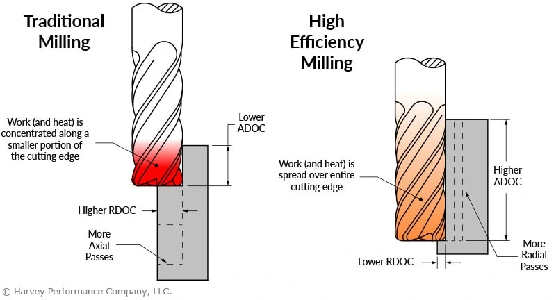
infographic examining depth of cut differences between HEM and traditional milling

Built-In CAM Applications

Machining technology has been advancing with the development of faster, more powerful machines. In order to keep up, many CAM applications have developed built-in features for HEM toolpaths, including Trochoidal Milling, a method of machining used to create a slot wider than the cutting tool’s cutting diameter.

HEM is largely based on the theory surrounding Radial Chip Thinning, or the phenomenon that occurs with varying RDOC, and relates to the chip thickness and feed per tooth. HEM adjusts parameters to maintain a constant load on the tool through the entire roughing operation, resulting in more aggressive material removal rates (MRR). In this way, HEM differs from other high performance toolpaths, which involve different methods for achieving significant MRR.

Click Here to learn More About The Efficiency-Boosting Power of High Efficiency Milling

Virtually any CNC machine can perform HEM – the key is a fast CNC controller. When converting from a regular program to HEM, about 20 lines of HEM code will be written for every line of regular code. A fast processor is needed to look ahead for the code, and keep up with the operation. In addition, advanced CAM software that intelligently manages tool load by adjusting the IPT and RDOC is also needed.

High Efficiency Milling Case Studies

The following example shows the result a machinist had when using a Helical Solutions HEV-5 tool to perform an HEM operation in 17-4PH stainless steel. While performing HEM, this ½” diameter, 5-flute end mill engaged the part just 12% radially, but 100% axially. This machinist was able to reduce tool wear and was able to complete 40 parts with a single tool, versus only 15 with a traditional roughing toolpath.
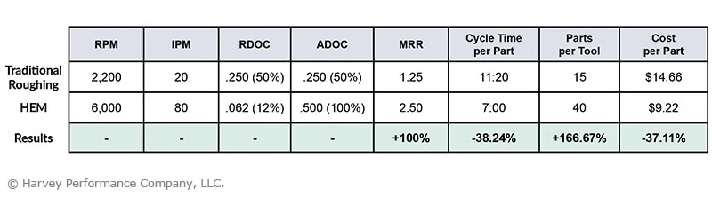
traditional roughing vs HEM comparison chart

The effect of HEM on a roughing application can also be seen in the case study below. While machining 6061 aluminum with Helical’s H45AL-C-3, a 1/2″, 3-flute rougher, this machinist was able to finish a part in 3 minutes, versus 11 minutes with a traditional roughing toolpath. One tool was able to make 900 parts with HEM, a boost of more than 150% over the traditional method.
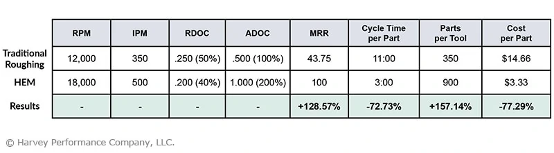
traditional roughing vs HEM comparison chart

Importance of Tooling to HEM

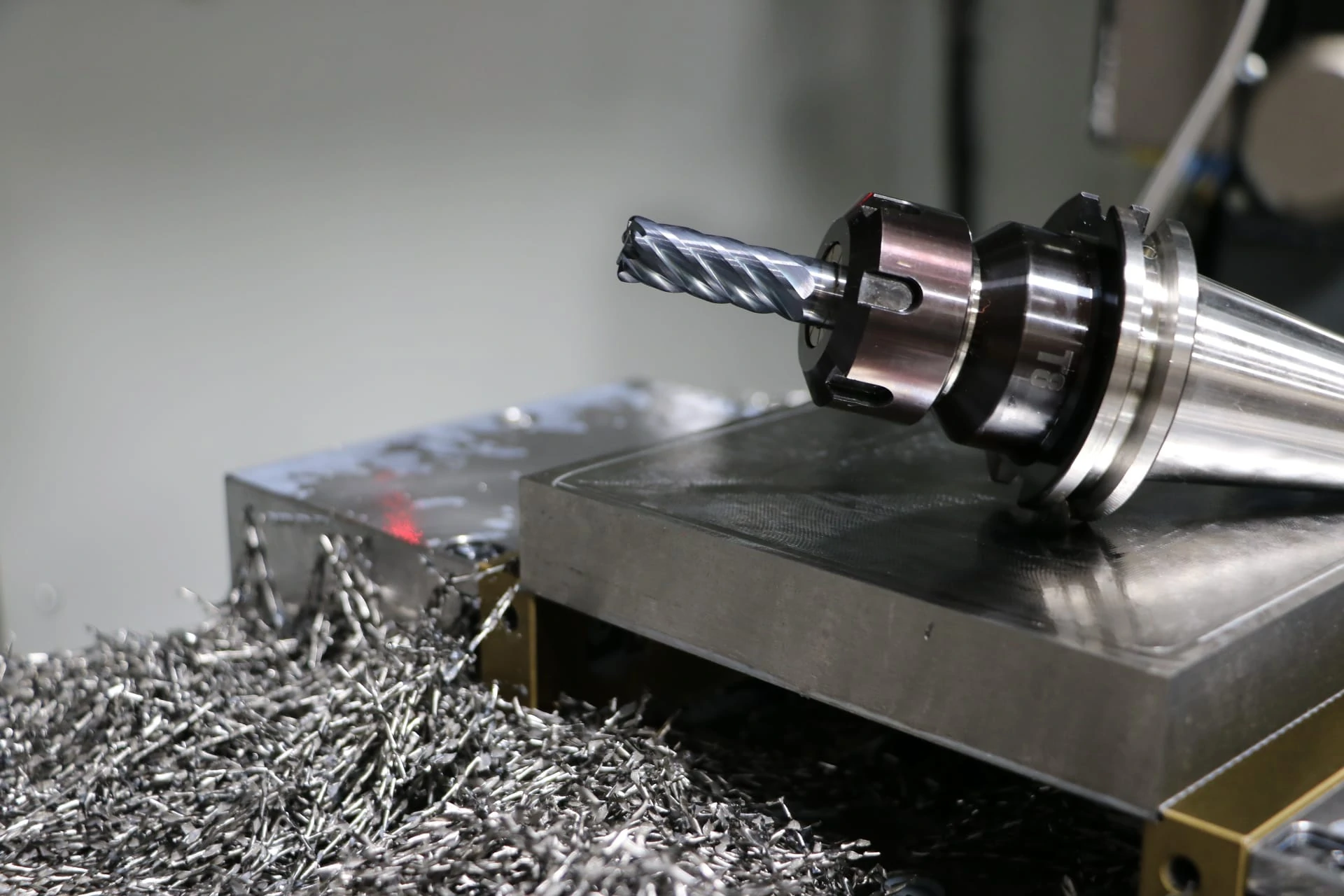
Generally speaking, HEM is a matter of running the tool – not the tool itself. Virtually every tool can perform HEM, but using tooling built to withstand the rigors of HEM will result in greater success. While you can run a marathon in any type of shoes, you’d likely get the best results and performance from running shoes.

HEM is often regarded as a machining method for larger diameter tooling because of the aggressive MRR of the operation and the fragility of tooling under 1/8” in size. However, miniature tooling can be used to achieve HEM, too.

Using miniature tooling for HEM can create additional challenges that must be understood prior to beginning your operation.

Best Tools for HEM:

  • High flute count for increased MRR.
  • Large core diameter for added strength.
  • Tool coating optimized for the workpiece material for increased lubricity.
  • Variable Pitch/Variable Helix design for reduced harmonics.

Key Takeaways

HEM is a machining operation which continues to grow in popularity in shops worldwide. A milling technique for roughing that utilizes a lower RDOC and higher ADOC than traditional milling, HEM distributes wear evenly across the cutting edge of a tool, reducing heat concentrations and slowing the rate of tool wear. This is especially true in tooling best suited to promote the benefits of HEM.
https://www.harveyperformance.com/wp-content/uploads/2017/08/Featured-Image-Intro-to-HEM-IMG.jpg 525 1400 Harvey Performance Company http://www.harveyperformance.com/wp-content/uploads/2018/08/Logo_HarveyPerformanceCompany-4.png Harvey Performance Company2017-08-11 15:33:262023-10-12 09:12:44Introduction to High Efficiency Milling

High Speed Machining vs. HEM

August 11, 2017/1 Comment/in CNC Machining, CNC Programming, High Efficiency Milling, Machining 101, Machining Techniques/by Tom Pyle

The following is just one of several blog posts relevant to High Efficiency Milling and High Speed Machining. To achieve a full understanding of this popular machining method, view any of the additional HEM posts below!

Introduction to High Efficiency Milling I How to Combat Chip Thinning I Diving into Depth of Cut I How to Avoid 4 Major Types of Tool Wear I Intro to Trochoidal Milling


Advancements in the metalworking industry have led to new, innovative ways of increasing productivity. One of the most popular ways of doing so (creating many new buzzwords in the process) has been the discovery of new, high-productivity toolpaths. Terms like trochoidal milling, high speed machining, adaptive milling, feed milling, and High Efficiency Milling are a handful of the names given to these cutting-edge techniques.

With multiple techniques being described with somewhat similar terms, there is some confusion as to what each is referring to. High Efficiency Milling (HEM) and High Speed Machining (HSM) are two commonly used terms and techniques that can often be confused with one another. Both describe techniques that lead to increased material removal rates and boosted productivity.  However, the similarities largely stop there.

High Speed Machining

High speed machining is often used as an umbrella term for all high productivity machining methods including HEM. However, HEM and HSM are unique, separate machining styles. HSM encompasses a technique that results in higher production rates while using a much different approach to depth of cut and speeds and feeds. While certain HEM parameters are constantly changing, HSM uses constant values for the key parameters. A very high spindle speed paired with much lighter axial depths of cut results in a much higher allowable feed rate. This is also often referred to as feed milling. Depths of cut involve a very low axial and high radial components. The method in general is often thought of as z-axis slice machining, where the tool will step down a fixed amount, machine all it can, then step down the next fixed amount and continue the cycle.

High speed machining techniques can also be applied to contoured surfaces using a ball profile or corner radius tool. In these situations, the tool is not used in one plane at a time, and will follow the 3 dimensional curved surfaces of a part. This is extremely effective for using one tool to bring a block of material down to a final (or close to final) shape using high resultant material removal rates paired with the ability to create virtually any shape.

High Efficiency Milling

HEM has evolved from a philosophy that takes advantage of the maximum amount of work that a tool can perform. Considerations for chip thinning and feed rate adjustment are used so that each cutting edge of a tool takes a consistent chip thickness with each rotation, even at varying radial depths of cut and while interpolating around curves. This allows machinists the opportunity to utilize a radial depth of cut that more effectively uses the full potential of a given tool. Utilizing the entire available length of cut allows tool wear to be spread over a greater area, prolonging tool life and lowering production costs. Effectively, HEM uses the depths associated with a traditional finishing operation but boosts speeds and feeds, resulting in much higher material removal rates (MRR). This technique is typically used for hogging out large volumes of material in roughing and pocketing applications.

In short, HEM is somewhat similar to an accelerated finishing operation in regards to depth of cut, while HSM is more of a high feed contouring operation. Both can achieve increased MRR and higher productivity when compared to traditional methods. While HSM can be seen as an umbrella term for all high efficiency paths, HEM has grown in popularity to a point where it can be classified on its own. Classifying each separately takes a bit of clarification, showing they each have power in certain situations.

Check out the video below to see HEM in action!

https://www.instagram.com/p/BV7voCVB4Ah/?taken-by=helicaltools

https://www.harveyperformance.com/wp-content/uploads/2017/08/Featured-Image-HSM-vs-HEM-IMG-1.jpg 525 1400 Tom Pyle http://www.harveyperformance.com/wp-content/uploads/2018/08/Logo_HarveyPerformanceCompany-4.png Tom Pyle2017-08-11 15:33:122023-10-12 09:11:55High Speed Machining vs. HEM

Tackling Titanium: Machining Tips and Techniques Guide

August 8, 2017/6 Comments/in CNC Machining, Gummy Materials, Helical Solutions, Machining Techniques, Material Specific, Milling, Tech Tips/by Tom Pyle

In today’s manufacturing industry, titanium and its alloys have become staples in aerospace, medical, automotive, and firearm applications. This popular metal is resistant to rust and chemicals, is recyclable, and is extremely strong for its weight. However, there are several challenges that must be considered when machining titanium and selecting the appropriate tools and parameters for the job.

Titanium Varieties

Titanium is available in many varieties, including nearly 40 ASTM grades, as well as several additional alloys. Grades 1 through 4 are considered commercially pure titanium with varying requirements on ultimate tensile strength. Grade 5 (Ti6Al4V or Ti 6-4) is the most common combination, alloyed with 6 percent aluminum and 4 percent vanadium. Although titanium and its alloys are often grouped together, there are some key differences between them that must be noted before determining the ideal machining approach.

Titanium 6AL4V chips with helical hvti end mill

Helical Solutions’ HVTI End Mill is a great choice for high efficiency toolpaths in Titanium.

Titanium Concerns

Workholding

Although titanium may have more desirable material properties than your average steel, it also behaves more flexibly, and is often not as rigid as other metals. This requires a secure grip on titanium workpieces, and as rigid a machine setup as is possible. Other considerations include avoiding interrupted cuts, and keeping the tool in motion at all times of contact with the workpiece. Dwelling in a drilled hole or stopping a tool next to a profiled wall will cause the tool to rub – creating excess heat, work-hardening the material, and causing premature tool wear.

Heat Generation

Heat is a formidable enemy, and heat generation must be considered when selecting speeds and feeds. While commercially pure grades of titanium are softer and gummier than most of its alloys, the addition of alloying elements typically raises the hardness of titanium. This increases concerns regarding generated heat and tool wear. Maintaining a larger chipload and avoiding unnecessary rubbing aids with tool performance in the harder titanium alloys, and will minimize the amount of work hardening produced. Choosing a lower RPM, paired with a larger chipload, can provide a significant reduction in temperature when compared to higher speed options. Due to its low conduction properties, keeping temperatures to a minimum will put less stress on the tool and reduce wear. Using high-pressure coolant is also an effective method to reduce heat generation when machining titanium.

mitsubishi evo camshaft cutters machine from titanium with helical solutions end mill

These camshaft covers were custom made in titanium for Mitsubishi Evos.
Photo courtesy of @RebootEng (Instagram)

Galling and Built-Up Edge

The next hurdle to consider is that titanium has a strong tendency to adhere to a cutting tool, creating built up edge. This is a tricky issue which can be reduced by using copious amounts of high pressure coolant aimed directly at the cutting surface. The goal is to remove chips as soon as possible to prevent chip re-cutting, and keep the flutes clean and clear of debris. Galling is a big concern in the commercially pure grades of titanium due to their “gummy” nature. This can be addressed using the strategies mentioned previously, such as continuing feed at all times of workpiece contact, and using plenty of high-pressure coolant.

Titanium Solutions

While the primary concerns when machining titanium and its alloys may shift, the methods for mitigating them remain somewhat constant. The main ideas are to avoid galling, heat generation, work hardening, and workpiece or tool deflection. Use a lot of coolant at high pressure, keep speeds down and feeds up, keep the tool in motion when in contact with the workpiece, and use as rigid of a setup as possible.

In addition, selecting a proper tool coating can help make your job a successful one. With the high heat being generated during titanium machining operations, having a coating that can adequately deal with the temperature is key to maintaining performance through an operation. The proper coating will also help to avoid galling and evacuate chips effectively. Coatings such as Harvey Tool’s Aluminum Titanium Nitride (AlTiN Nano) produce an oxide layer at high temperatures, and will increase lubricity of the tool.

Tooling Solutions

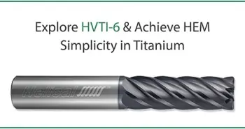
Helical Solutions offers the HVTI-6 line of tooling optimized for High Efficiency Milling (HEM) in Titanium and its alloys. Helical’s HVTI-6 features its Aplus coating which offers added lubricity and high temperature resistance for improved tool life and faster speeds and feeds.

As titanium and its many alloys continue to grow in use across various industries, more machinists will be tasked with cutting this difficult material. However, heat management and appropriate chip evacuation, when paired with the correct coating, will enable a successful run and profitable tool life.

machining titanium

https://www.harveyperformance.com/wp-content/uploads/2017/08/Featured-Image-Tackling-Titanium-IMG.jpg 525 1400 Tom Pyle http://www.harveyperformance.com/wp-content/uploads/2018/08/Logo_HarveyPerformanceCompany-4.png Tom Pyle2017-08-08 16:00:512025-11-12 15:53:48Tackling Titanium: Machining Tips and Techniques Guide

Harrelson Trumpets – Featured Customer

August 7, 2017/1 Comment/in Featured Customer/by Harvey Performance Company

Featured Image Courtesy of Harrelson Trumpets

Harrelson Trumpets is a custom trumpet manufacturer based out of Denver, Colorado. As the only trumpet manufacturer that produces many of their parts on a CNC machine, Harrelson Trumpets has become widely recognized as one of the top custom instrument manufacturers in the world. Harrelson Trumpets are manufactured using a technology called Standing Wave Efficiency (SWE). Put simply, SWE Mod Kits reduce energy loss in the instrument, thus increasing efficiency. This translates to playing an instrument with less effort, improved attacks, flexibility, slotting, endurance and dynamics.

Jason Harrelson is the founder and owner of Harrelson Trumpets. He has been researching and applying SWE technology since 1993, both in the lab and real world playing situations. As of 2017, Harrelson has personally built more than 800 unique trumpet designs and 1,200 individual trumpets. We spoke with Harrelson about his history as an entrepreneur, how CNC machining changed the way he worked, and more.


harrelson trumpets

Photo Courtesy of: Harrelson Trumpets

Tell us about how you started Harrelson Trumpets and some of the products you manufacture.

I started out modifying my own trumpet when I discovered it didn’t play as well as my friend’s trumpet. I wondered why my friends with the same brand of trumpet could hit certain notes more easily or make a more beautiful tone. So, it started off as something I was doing for myself. Fast forward many years and I sold a trumpet I had modified that was collecting dust in a closet. I soon realized there is a huge market for custom trumpets that play easier. I bought old horns at pawn shops or music stores and modified and sold them for a few years, but that approach was a lot of work. Every trumpet manufacturer uses different bore and thread sizing. I was constantly reverse engineering each and every modification I did. So, the decision was made to come out with a line of instruments that we built from the ground up utilizing the physics principals I’d learned in my physics program in college. Many years of research, development and hard work were invested to produce the most technologically advanced trumpets available in the world. We have extended the application of our “Science Meets Sound” model into a series of accessories that improve the efficiency of other brand trumpets as well. We offer a fully modular 5MM mouthpiece, mod kits, and a variable gap receiver, just to name a few. We are launching several new products in the near future that also apply science and machining in an industry that has been unchanged for hundreds of years.

What made you get into machining?

Machining was a natural progression. Most of my designs are not possible with traditional fabrication techniques so precision machining was the logical next step. CNC machines were a necessity in allowing us to prototype and eventually put into production designs that revolutionized the industry. We are the only trumpet manufacturer in the world that produces our tuning slides, bell crooks and leadpipes (as well as most other parts) on a CNC Machine.

harrelson trumpets

Photo Courtesy of: Harrelson Trumpets

As someone who was self-taught in CNC Machining, what was your biggest hurdle?

Well, I think learning so many different machining and fabrication processes is the biggest challenge. We use modified machines to achieve our end goal. Most of our processes have required specialty tooling such as spindle speeders up to 90,000 rpm to create the high detail features and artwork that looks almost like they were a coin struck by a die.

What is your favorite part of this profession?

Problem solving. Finding solutions. Helping others raise their standards musically while incorporating science-based solutions.

harrelson trumpets

Photo Courtesy of: Harrelson Trumpets

You use a lot of Harvey Tool products in your shop. How have Harvey Tool products impacted your overall shop performance?

When we first started using them, Harvey Tool was the only small tool manufacturer for miniature end mills that I could find online. The wide range of tooling available from Harvey has allowed us to create fine detailed artwork in components that otherwise wouldn’t be possible. It’s a large part of our business to offer custom art and machining. I don’t think I’ve ever had to order anything custom because they’ve always had something that worked right off the shelf for my applications.

Tell us about your favorite project that Harvey Tools helped to create.

Any of our custom Summit Art Trumpets would be included in that category. We do a special Satchmo Trumpet every year and donate it to French Quarter Festivals in New Orleans. These are fun projects because they really let us flex our artistic and machining muscles. Some of the Satchmo Trumpets would not have been possible if it weren’t for Harvey Tool.

harrelson trumpets

Photo Courtesy of: Harrelson Trumpets

If you were stranded on a desert island with only one Harvey Tool, which would it be, and why?

I couldn’t live with only one! I would choose the catalog so I could dream of getting off the island and back into the shop!

You have been an entrepreneur for your entire life. What do you think was the major reason you were able to make Harrelson Trumpets your full-time job?

I have been inventing and trying my hand at different businesses my whole life. I think that the reason Harrelson Trumpets was and is a success is two-fold. We have put countless long and hard hours into learning and mastering our trade. Hard work really is a major factor in our success. Beyond that, I love music, science and inventing solutions for my customers. I have made it my life’s work to create a superior trumpet and this is an endless quest that keeps me motivated. It is very rewarding work. There is great satisfaction in delivering an heirloom quality instrument that is scientifically superior to all others and brings joy to the musician making music with it for generations to come.

harrelson trumpets

Photo Courtesy of: Harrelson Trumpets

If you could give one piece of advice to a new machinist ready to #PlungeIntoMachining, what would it be?

Ask other professionals in your field for help. I assist other machinists daily via email, social media, phone, and in person. Seek out mentors and learn from their experiences as often as possible. Most of what I have learned was a culmination of reading, trying, failing, reading again, trying again, and eventually finding what works. But today, we have resources like YouTube, Instagram, and online or in-person classes held by private individuals rather than full fledged college courses. You can learn as fast as you want through these non-traditional avenues!

Is there anything else you would like to share with the In The Loupe community?

Loyalty to a brand IS very important and almost always results in greater productivity and success. I mention this because many people assume the cheapest tool is the right tool. In reality, knowing your tooling is worth every penny and paying a premium over cheap imports is the wise decision. Working with tooling from the same manufacturer day after day and year after year provides the end user with benefits including reliable performance expectations, accuracy, quality and availability. To this end, be loyal to the best tooling manufacturer you can afford!

harrelson trumpets with harvey end mill

Photo Courtesy of: Harrelson Trumpets

Would you like to be considered for a future “Featured Customer” blog? Click here to submit your information.

Photos courtesy of Harrelson Trumpets

https://www.harveyperformance.com/wp-content/uploads/2017/08/Featured-Image-Harrelson-Trumpets-IMG.jpg 525 1400 Harvey Performance Company http://www.harveyperformance.com/wp-content/uploads/2018/08/Logo_HarveyPerformanceCompany-4.png Harvey Performance Company2017-08-07 03:30:522022-06-08 11:37:57Harrelson Trumpets – Featured Customer

Reducing Tool Runout

July 25, 2017/3 Comments/in CNC Machining, How-To's, Machining 101, Quick Tips, Troubleshooting Tips/by Harvey Performance Company

Tool runout is a given in any machine shop, and can never be 100% avoided. Thus, it is important to establish an acceptable level of runout for any project, and stay within that range to optimize productivity and prolong tool life. Smaller runout levels are always better, but choice of machine and tool holder, stick-out, tool reach, and many other factors all have an influence on the amount of runout in every setup.

Defining Tool Runout

Tool runout is the measurement of how far a cutting tool, holder, or spindle rotates off of its true axis. This can be seen in low quality end mills where the cutting diameter is true to size when measured while stationary, but measures above tolerance while rotating.

The first step to minimizing runout is understanding what individual factors cause runout in every machine setup. Runout is seen in the accuracy of every cutting tool, collet, tool holder, and spindle. Every added connection between a machine and the workpiece it is cutting will introduce a higher level of runout. Each increase can add to the total runout further and further. Steps should be taken with every piece of tooling and equipment to minimize runout for best performance, increased tool life, and quality finished products.

Measuring Runout

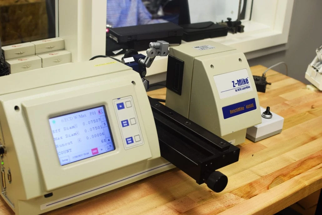
Determining the runout of your system is the first step towards finding how to combat it. Runout is measured using an indicator that measures the variation of a tool’s diameter as it rotates. This is done with either a dial/probe indicator or a laser measuring device. While most dial indicators are both portable and easy to use, they are not as accurate as the available laser indicators, and can also make a runout measurement worse by pushing on a tool. This is mostly a concern for miniature and micro-tooling, where lasers should be strictly used due to the tool’s fragile nature.  Most end mill manufacturers recommend using a laser runout indicator in place of a dial indicator wherever possible.

Z-Mike Laser

Z-Mike laser measurement devices are common instruments used to measure levels of tool runout.

Runout should be measured at the point where a tool will be cutting, typically at the end of the tools, or along a portion of the length of cut. A dial indicator may not be plausible in these instances due to the inconsistent shape of a tool’s flutes. Laser measuring devices offer another advantage due to this fact.

High Quality Tools

The amount of runout in each component of a system, as-manufactured, often has a significant impact on the total runout of a given setup. Cutting tools all have a restriction on maximum runout allowed when manufactured, and some can have allowances of .0002” or less. This is often the value that should be strived for in a complete system as well. For miniature tooling down to .001” diameter, this measurement will have to be held to an even smaller value. As the ratio of tool runout to tool diameter becomes larger, threats of tool failure increase. As stated earlier, starting with a tool that has minimal runout is pivotal in keeping the total runout of a system to a minimum. This is runout that cannot be avoided.

Precision Tool Holders

The next step to minimizing runout is ensuring that you are using a high quality, precision tool holder. These often come in the form of shrink-fit, or press-fit tool holders offering accurate and precise tool rotation.  Uniform pressure around the entire circumference of a shank is essential for reducing runout. Set screw based holders should be avoided, as they push the tool off-center with their uneven holding pressure.  Collet-based tool holders also often introduce an extra amount of runout due to their additional components. Each added connection in a tool holding system allows more methods of runout to appear. Shrink-fit and press-fit tool holders are inherently better at minimizing runout due to their fewer components.

end mill in holder above completed part

Included in your tool holding considerations should be machine tool cleanliness. Often, chips can become lodged in the spindle, and cause an obstruction between two high-precision surfaces in the system. Ensuring that your tool holder and spindle are clean and free of chips and debris is paramount when setting up for every job.

Shank Modifications

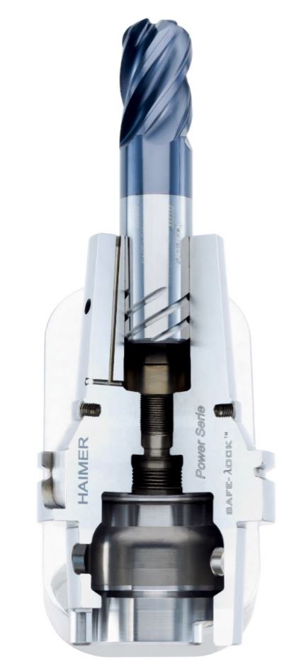
Apart from equipment itself, many other factors can contribute to an increasing amount of tool runout. These can include how long a tool is, how rigid a machine setup is, and how far a tool is hanging out of its holder.  Shank modifications, along with their methods of tool holding can have a large impact. Often thought of as an older, obsolete technology, Weldon flats are found guilty of adding large amounts of runout in many shops. While many shops still use Weldon flats to ensure a secure grip on their tools, having a set screw pushing a tool to one side can push it off center, yielding very high levels of runout. Haimer Safe Lock™ is another option increasing in popularity that is a much higher performance holding technology. The Safe-Lock™ system is designed with the same tolerances as shrink fit and other high precision tool holders. It is able to minimize runout, while firmly holding a tool in place with no chance of pull-out.

haimer safe lock tool holder for reducing tool runout

The Haimer Safe-Lock™ system is one option to greatly reduce tool runout.

Runout will never be completely eliminated from a machining system. However, steps can (and should) be taken to keep it to a minimum using every method possible. Keeping a tool running true will extend tool life, increase performance, and ultimately save your shop time and money. Runout is a common concern in the metalworking industry, but it is often overlooked when it could be main issue causing part rejections and unacceptable results. Every piece of a machine tool plays a part in the resultant runout, and none should be overlooked.

https://www.harveyperformance.com/wp-content/uploads/2017/07/Feature-Image-Tool-Runout-IMG.jpg 525 1400 Harvey Performance Company http://www.harveyperformance.com/wp-content/uploads/2018/08/Logo_HarveyPerformanceCompany-4.png Harvey Performance Company2017-07-25 11:45:352023-10-12 09:05:18Reducing Tool Runout

Most Common Methods of Tool Entry

July 17, 2017/6 Comments/in CNC Machining, CNC Programming, Holemaking, Machining 101, Machining Techniques, Milling, Tech Tips/by Harvey Performance Company

Tool entry is pivotal to machining success, as it’s one of the most punishing operations for a cutter. Entering a part in a way that’s not ideal for the tool or operation could lead to a damaged part or exhausted shop resources. Below, we’ll explore the most common part entry methods, as well as tips for how to perform them successfully.


Pre-Drilled Hole

Pre-drilling a hole to full pocket depth (and 5-10% larger than the end mill diameter) is the safest practice of dropping your end mill into a pocket. This method ensures the least amount of end work abuse and premature tool wear. It also facilitates smoother chip evacuation, reducing the risk of chip buildup and potential tool breakage. Machinists often use this technique when working with materials prone to chip welding or built-up edge formation, ensuring consistent machining performance.

tool entry predrill


Helical Interpolation

Helical Interpolation is a very common and safe practice of tool entry with ferrous materials. Employing corner radius end mills during this operation will decrease tool wear and lessen corner breakdown. With this method, use a programmed helix diameter of greater than 110-120% of the cutter diameter. Moreover, helical interpolation offers advantages in achieving precise surface finishes, making it a preferred choice for applications requiring high precision and surface quality, such as aerospace and medical device manufacturing.

helical interpolation


Ramping-In

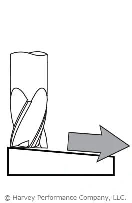
This type of operation can be very successful, but institutes many different torsional forces the cutter must withstand. A strong core is key for this method, as is room for proper chip evacuation. Using tools with a corner radius, which strengthen its cutting portion, will help. Additionally, ramping-in allows for efficient material removal with reduced axial forces, minimizing workpiece distortion and enhancing dimensional accuracy. Machinists often employ this technique in contouring and pocketing operations, where maintaining part integrity is crucial.

ramping

Suggested Starting Ramp Angles:

Hard/Ferrous Materials: 1°-3°

Soft/Non-Ferrous Materials: 3°-10°

For more information on this popular tool entry method, see Ramping to Success.


Arcing

This method of tool entry is similar to ramping in both method and benefit. However, while ramping enters the part from the top, arcing does so from the side. The end mill follows a curved tool path, or arc, when milling, this gradually increasing the load on the tool as it enters the part. Additionally, the load put on the tool decreases as it exits the part, helping to avoid shock loading and tool breakage. Machinists often utilize this technique in mold making, die sinking, and 3D contouring operations, enhancing productivity and surface finish quality.

arching with end mill


Straight Plunge

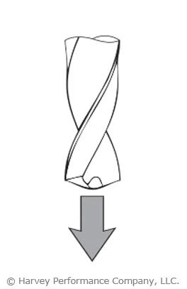
This is a common, yet often problematic method of entering a part. A straight plunge into a part can easily lead to tool breakage. If opting for this machining method, however, certain criteria must be met for best chances of machining success. The tool must be center cutting, as end milling incorporates a flat entry point making chip evacuation extremely difficult. Drill bits are intended for straight plunging, however, and should be used for this type of operation.

tool entry


Straight Tool Entry

Straight entry into the part takes a toll on the cutter, as does a straight plunge. Until the cutter is fully engaged, the feed rate upon entry is recommended to be reduced by at least 50% during this operation. Machinists often resort to straight tool entry in simple machining operations with limited tool access or where other entry methods are impractical. However, it’s crucial to monitor tool wear and chip evacuation carefully to prevent chip buildup and potential tool breakage. Adjusting cutting parameters based on material properties and part geometry can further enhance machining efficiency and tool life.

tool entry


Roll-In Tool Entry

Rolling into the cut ensures a cutter to work its way to full engagement and naturally acquire proper chip thickness. The feed rate in this scenario should be reduced by 50%. Roll-in tool entry is particularly advantageous in slotting and profiling operations, where maintaining consistent chip thickness is critical for surface finish quality and dimensional accuracy. Machinists often utilize this technique in high-speed machining applications, maximizing material removal rates while minimizing tool wear and heat generation.

tool entry

Mastering various tool entry techniques is essential for machining success. By understanding and implementing these methods effectively, machinists can optimize performance while prolonging the lifespan of their tools. Continual evaluation of cutting conditions and adaptation of entry strategies based on material properties and part geometry are key to achieving superior machining results.

https://www.harveyperformance.com/wp-content/uploads/2017/07/Feature-Image-Tool-Entry-IMG.jpg 525 1400 Harvey Performance Company http://www.harveyperformance.com/wp-content/uploads/2018/08/Logo_HarveyPerformanceCompany-4.png Harvey Performance Company2017-07-17 14:53:062024-03-20 11:54:31Most Common Methods of Tool Entry

Intro to Trochoidal Milling

June 28, 2017/3 Comments/in CNC Machining, CNC Programming, High Efficiency Milling, Machining Techniques, Tech Tips, Tools In Action/by Harvey Performance Company

The following is just one of several blog posts relevant to High Efficiency Milling. To achieve a full understanding of this popular machining method, view any of the additional HEM posts below!

Introduction to High Efficiency Milling I High Speed Machining vs. HEM I How to Combat Chip Thinning I Diving into Depth of Cut I How to Avoid 4 Major Types of Tool Wear


What Is Trochoidal Milling?

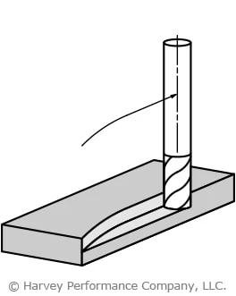
Trochoidal milling is a method of machining used to create a slot wider than the cutting tool’s cutting diameter. This is accomplished using a series of circular cuts known as a trochoidal tool path. A form of High Efficiency Milling (HEM), trochoidal milling leverages high speeds while maintaining a low radial depth of cut (RDOC) and a high axial depth of cut (ADOC).

Trochoidal milling is largely based on the theory surrounding chip thinning in machining. Conventional thinking suggests that cutting tools have an optimal chip load that determines the ideal width and size of the chips produced. The concept of combating chip thinning involves machining with a chip load that is larger than “optimal” in order to maintain a constant maximum chip thickness.

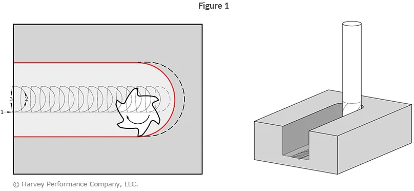
In contrast to a completely linear radial tool path in conventional machining, trochoidal milling takes advantage of a spiral tool path with a low RDOC to reduce load and wear on the tool (Figure 1).

trochoidal milling toolpath displayed

Advantages of Trochoidal Milling

  • Decreased cutting forces
  • Reduced heat
  • Greater machining accuracy
  • Improved tool life
  • Faster cycle times
  • One tool for multiple slot sizes

Trochoidal milling can be very advantageous in certain applications. The reduced radial engagement of the cutting edge decreases the amount of heat produced in the cut while also decreasing the cutting forces and load on the spindle. The reduced radial forces allow for greater accuracy during production and make it possible to machine finer and more precise features on a part.

In addition, the lower radial depth of cut allows for a higher axial depth of cut, meaning that the entire length of the cutting edge can be utilized. This ensures that heat and cutting forces are distributed across the tool’s cutting edge, rather than concentrated on a single section. The reduced heat and wear, combined with their uniform spread on the cutting edge, resulting in significantly improved tool life over conventional slotting methods.

Given the reduced destructive forces, the cutting tool’s speeds can be increased. Since the entire length of cut is utilized, trochoidal milling can eliminate the need for multiple axial depths of cut. Increased running parameters and a reduced number of passes greatly reduce cycle time.

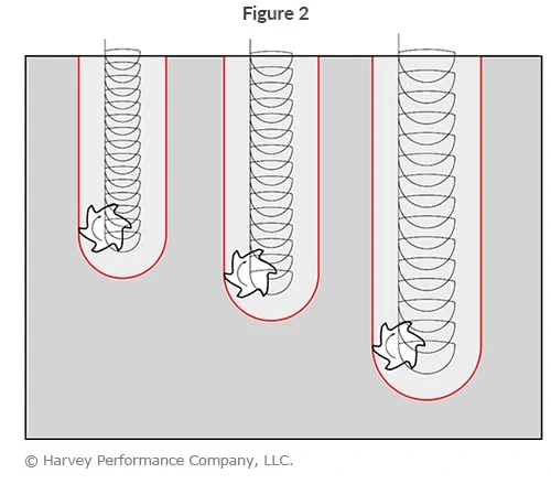
Since trochoidal milling uses a tool to machine a slot wider than its cutting diameter, the same tool can be used to create slots of varying sizes, rather than just one. This can free up space in your tool carousel and save time on tool change-outs, depending on the requirements of the part (Figure 2).

trochoidal milling paths of different sizes with same tool

Although slotting is a roughing operation, the reduced radial depth of cut and decreased cutting forces from trochoidal milling often result in an improved finish over a conventional slotting toolpath. However, a finishing pass along the walls of the workpiece might be required to remove any cusps left from the spiral motion of the cutting tool.

Click Here to Learn More About The Efficiency-Boosting Power of High Efficiency Milling

Challenges of Trochoidal Milling

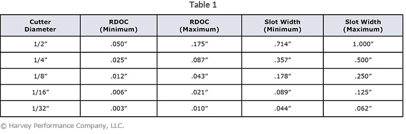
The challenges of trochoidal milling are typically found with the machinery and software. The right machine to take advantage of trochoidal milling will not only be capable of high speeds and feeds but will also be capable of a constantly changing feed rate as the tool moves along it’s spiral path. Inability to have a changing feed rate will cause chip thinning which can yield non-ideal results and potentially cause tool breakage. Special software might also be required to program tool paths and feed rates for this process. This is further complicated by factors like the ratio of the cutter diameter to the size of the groove, as well as the radial depth of cut for these different ratios. Most figures suggest the cutter diameter be 50%-70% of the final slot width, while the radial depth of cut should equal 10%-35% of cutter diameter (Table 1), but the safest option is always to consult the tool manufacturer.

trochoidal milling diameter, depths of cut, and slot width chart

Trochoidal Milling and Micromachining

Benefits When Micromachining

Micromachining can also benefit from trochoidal milling. The decreased radial engagement and lower cutting forces produced during a trochoidal tool path put less force on the cutting tools. This is especially important for smaller diameter tools, as they are weaker and less rigid, and the reduced cutting forces decrease the chance of deflection and breakage.

Challenges When Micromachining

While trochoidal milling with miniature tooling is theoretically beneficial, there are additional challenges associated with smaller tools. Miniature cutting tools are much more susceptible to breakage due to spindle runout and vibration, material inconsistencies, uneven loading, and many other variables that arise during machining. Depending on your application, it may be worth using the tool with the greatest diameter for the extra strength. Although there are potential benefits at the miniature level, more attention must be paid to the machine setup and material to ensure the tools have the highest chance of success.

Just like HEM, as a general rule, trochoidal milling should not be considered when using tools with cutting diameters less than .031”. While possible, trochoidal milling may still be prohibitively challenging or risky at diameters below .062”, and your application and machine must be considered carefully.

Conclusion

Trochoidal milling is a High Efficiency Milling technique (high speed, high ADOC, low RDOC) characterized by a circular, or trochoidal, tool path. This milling style is proven to offer significant machining process benefits, such as increasing tool life, reducing machining times, and fewer tools required for a job. However, it is critical to have a machine and software capable of high speeds and feeds and constantly changing feed rates to avoid critical tool failure. While miniature tools can still benefit from trochoidal milling, the risk of tool breakage must be considered carefully, especially at cutter diameters below .062”. Although trochoidal milling can increase your machining efficiency in many applications, it is always a good idea to consult your tool manufacturer beforehand.

A great example of trochoidal milling in action can be seen in this video, where a 1/2″ Helical Solutions end mill with variable helix, variable pitch was used to machine a block of 316 stainless steel.

https://www.harveyperformance.com/wp-content/uploads/2017/06/Feature-Image-Trochoidal-Milling-IMG.jpg 525 1400 Harvey Performance Company http://www.harveyperformance.com/wp-content/uploads/2018/08/Logo_HarveyPerformanceCompany-4.png Harvey Performance Company2017-06-28 16:00:492023-10-12 08:58:35Intro to Trochoidal Milling

Corner Engagement: How to Machine Corners

May 15, 2017/1 Comment/in CNC Machining, CNC Programming, How-To's, Machining Techniques, Milling, Troubleshooting Tips/by Harvey Performance Company

Understanding Corner Engagement

During the milling process, and especially during corner engagement, tools undergo significant variations in cutting forces. One common and difficult situation is when a cutting tool experiences an “inside corner” condition. This is where the tool’s engagement angle significantly increases, potentially resulting in poor performance.

Challenges of Corner Engagement

Engaging corners improperly can lead to various issues, affecting both performance and quality. Some common challenges include:

  • Chatter:  – visible imperfections in corner finishes
  • Deflection – detected by unwanted wall taper measurements
  • Strange cutting sound – tool squawking or chirping in the corners
  • Tool breakage/failure or chipping – resulting from excessive stress or improper handling

Least Effective Approach (Figure 1)

Generating an inside part radius that matches the radius of the tool at a 90° direction range is not a desirable approach to machining a corner. In this approach, the tool experiences extra material to cut (dark gray), an increased engagement angle, and a direction change. As a result, issues including chatter, tool deflection/ breakage, and poor surface finish may occur.

Feed rate may need to be lessened depending on the “tool radius-to-part radius ratio.”

90 degree end mill corner engagement

More Effective Approach (Figure 2)

Generating an inside part radius that matches the radius of the tool with a sweeping direction change is a more desirable approach for corner engagement. The smaller radial depths of cut (RDOC) in this example help to manage the angle of engagement, but at the final pass, the tool will still experience a very high engagement angle.  Common results of this approach will be chatter, tool deflection/breakage and poor surface finish.

Feed rate may need to be reduced by 30-50% depending on the “tool radius-to-part radius ratio.”

corner engagement effective approach with multiple rdocs at 90 degrees

Most Effective Approach For Corner Engagement (Figure 3)

Generating an inside part radius with a smaller tool and a sweeping action creates a much more desirable machining approach. The manageable RDOC and smaller tool diameter allow for management of the tool engagement angle, higher feed rates and better surface finishes. As the cutter reaches full radial depth, its engagement angle will increase, but the feed reduction should be much less than in the previous approaches.

Feed rate may need to be heightened depending on the “tool-to-part ratio.” Utilize tools that are smaller than the corner you are machining.

most effective corner engagement of multiple passes into corner

Corner engagement is a critical aspect of machining that demands attention to detail and strategic planning. By implementing effective techniques and leveraging appropriate tools, manufacturers can overcome challenges associated with corner machining and achieve superior results.

https://www.harveyperformance.com/wp-content/uploads/2017/05/Featured-Image-Corner-Engagement-IMG.jpg 525 1400 Harvey Performance Company http://www.harveyperformance.com/wp-content/uploads/2018/08/Logo_HarveyPerformanceCompany-4.png Harvey Performance Company2017-05-15 07:00:142024-04-16 14:18:21Corner Engagement: How to Machine Corners

Ramping to Success

May 10, 2017/1 Comment/in CNC Machining, CNC Programming, Machining Techniques, Milling, Tech Tips/by Harvey Performance Company

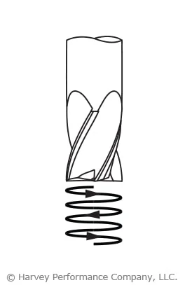
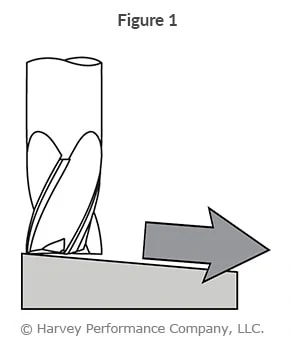
Poor tool life and premature tool failure are concerns in every machining application. Something as simple as tool path selection – and how a tool first enters a part – can make all the difference. Tool entry has a great deal of influence on its overall success, as it’s one of the most punishing operations for a cutter. Ramping into a part, via a circular or linear toolpath, is one of the most popular and oftentimes the most successful methods (Figure 1). Below, learn what ramping is, its benefits, and in which situations it can be used.

illustrated end mill ramping into part

Check Out Our Micromachining Webinar to Get More Life Out of Your Miniature Cutting Tools

What is Ramping?

Ramping refers to simultaneous radial and axial motion of a cutting tool, making an angular tool path. Oftentimes, this method is used to approach a part when there is a need to create closed forms such as pockets, cavities, engravings, and holes. In doing so, the need to plunge with an end mill or drill to create a starting point is eliminated. Ramping is particularly important in micromachining where even the slightest imbalance in cutting forces can cause tool failure.

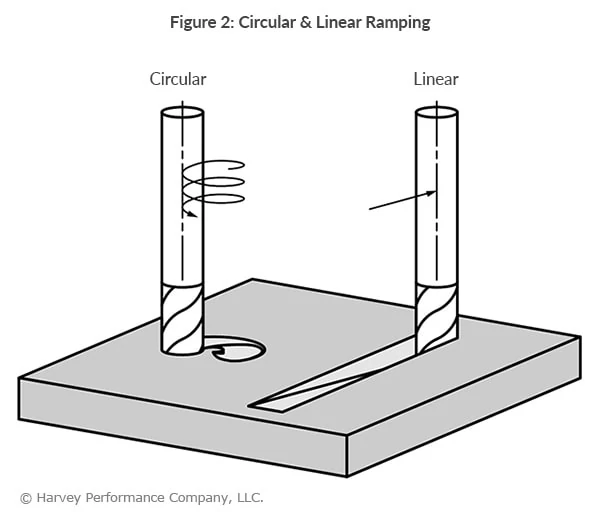
There are two types of ramping toolpaths: Linear and Circular (Figure 2 ).

circular and linear ramping

Linear Ramping involves moving a cutting tool along two axes (the z-axis and one of the x, y axes). This method has significant more radial engagement with complementary increased cutting forces distributed across only two axes.

Circular Ramping (Helical Interpolation) has a spiral motion of the cutting tool that engages all three axes (x, y, and z axes). This method typically has less radial engagement on the cutting tool, with the cutting forces distributed across the three different axes. This is the recommended method, as it ensures the longest tool life.

Suggested Starting Ramp Angles:

Soft/Non-Ferrous Materials: 3° – 10°

Hard/Ferrous Materials 1° – 3°

Benefits of Ramping

When a tool enters the part via a Ramping method, it gradually increases in depth, preventing any shock loading on end mills. This reduces costs resulting from unnecessary tool breakage. Ramping produces smaller chips when compared to plunging, which makes chip evacuation faster and easier. As a result, cycle time can be decreased by running the end mill at faster parameters. Ramping also creates an extra space in the tool changer that would otherwise be occupied by a drill purposed with machining a starter hole.

Arcing

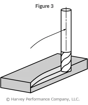
Similar to ramping in both method and benefit, arcing is another technique of approaching a workpiece (See Figure 3).

illustration of end mill arcing tool entry

While ramping enters the part from the top, arcing enters from the side. The end mill follows a curved tool path (or arc) when milling, thus gradually increasing the load on the tool as the tool enters the part, as well as gradually decreasing the load as the tool exits the part. In this way, shock loading and possible tool breakage are avoided.

For more information on ramping, arcing, and other tool entry methods, please see Helical Solutions’ “Types of Tool Entry.” 

https://www.harveyperformance.com/wp-content/uploads/2017/05/Featured-Image-Ramping-to-Success-IMG.jpg 525 1400 Harvey Performance Company http://www.harveyperformance.com/wp-content/uploads/2018/08/Logo_HarveyPerformanceCompany-4.png Harvey Performance Company2017-05-10 09:00:392023-10-12 08:24:58Ramping to Success

Climb Milling vs. Conventional Milling

May 5, 2017/28 Comments/in CNC Machining, CNC Programming, Machining Techniques, Tech Tips/by Harvey Performance Company

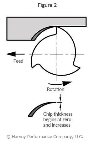
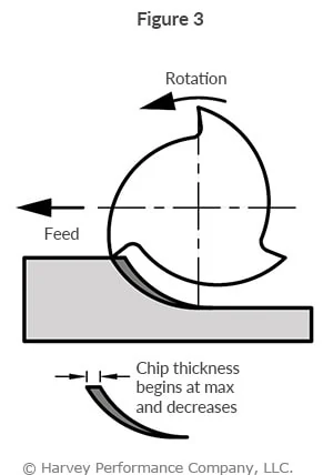
There are two distinct ways to cut materials when CNC milling: Conventional Milling (Up) and Climb Milling (Down). The difference between these two techniques is the relationship of the rotation of the cutter to the direction of feed. In Conventional Milling, the cutter rotates against the direction of the feed. During Climb Milling, the cutter rotates with the feed.

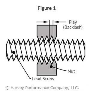
Conventional Milling is the traditional approach when cutting because the backlash, or the play between the lead screw and the nut in the machine table, is eliminated as seen in Figure 1 below. Recently, however, Climb Milling has been recognized as the preferred way to approach a workpiece since most machines today compensate for backlash or have a backlash eliminator.

infographic showcasing conventional milling with backlash elimination


Key Conventional and Climb Milling Properties:

Conventional Milling (Figure 2)

As previously stated, traditionally conventional milling has been the common choice for most machinists. This is where the cutting edge of the tool is actually rotating away from the direction of the feed. An example of this is seen in Figure 2 below. Until recently, this has been the common choice due to backlash however, the rise of climb milling has caused machinists or machines to adapt and compensate for this issue.

That is not to say there aren’t benefits to climb milling. For example, this strategy offers a machinist more control and less vibration than its climb milling counterpart. Similarly, for materials that traditionally chatter or tear, conventional milling would be the proper strategy to choose. On the other hand, here are some reasons why it might be most beneficial to adopt a climb milling strategy:

  • Chip width starts from zero and increases which causes more heat to diffuse into the workpiece and produces work hardening
  • Tool rubs more at the beginning of the cut causing faster tool wear and decreases tool life
  • Chips are carried upward by the tooth and fall in front of cutter creating a marred finish and re-cutting of chips
  • Upwards forces created in horizontal milling* tend to lift the workpiece, more intricate and expansive work holdings are needed to lessen the lift created*

infographic of conventional milling and its feed and rotation paths

Climb Milling (Figure 3)

As machinists are always trying to find ways to increase efficiency and tool life, climb milling has gotten a lot of recent traction in the space. Less heat is generated within the tool, and friction is more easily mitigated. These two alone lead to longer tool life, allowing for more parts completed per tool, lowering a shops bottom line. Also, climb milling can lead to a better surface finish due to how the chips are formed at the cutting edge.

With more modern machines now compensating for backlash or utilize backlash eliminators, it has become a much easier strategy to adopt within shops. While we went over some reasons why climb milling is not an effective strategy above, here are some reasons why a machinist may want to explore climb milling:

  • Chip width starts from maximum and decreases so heat generated will more likely transfer to the chip
  • Creates cleaner shear plane which causes the tool to rub less and increases tool life
  • Chips are removed behind the cutter which reduces the chance of chip recutting
  • Downwards forces in horizontal milling is created that helps hold the workpiece down, less complex work holdings are need when coupled with these forces
  • Horizontal milling is when the center line of the tool is parallel to the work piece

infographic of climb milling and its rotation and feed comparisons


When to Choose Conventional or Climb Milling

Climb Milling is generally the best way to machine parts today since it reduces the load from the cutting edge, leaves a better surface finish, and improves tool life. During Conventional Milling, the cutter tends to dig into the workpiece and may cause the part to be cut out of tolerance.

However, though Climb Milling is often the current preferred way to machine parts, there are times when Conventional Milling is the necessary milling style. One such example is if your machine does not counteract backlash. In this case, Conventional Milling should be implemented. Without accounting for backlash, breakage can occur due to the forces within the machine during tool engagement.

In addition, conventional milling should also be utilized on casting, forgings or when the part is case hardened. This is due to the cut beginning under the surface of the material, where it will gradually build a chip. Climb milling into these materials will see maximum chip thickness on engagement, which could lead to premature failure of the cutting edge due to the forces generated.

https://www.harveyperformance.com/wp-content/uploads/2017/05/Feature-Image-Climb-vs-Conventional-IMG.jpg 525 1400 Harvey Performance Company http://www.harveyperformance.com/wp-content/uploads/2018/08/Logo_HarveyPerformanceCompany-4.png Harvey Performance Company2017-05-05 10:00:542023-11-17 14:53:45Climb Milling vs. Conventional Milling
Page 9 of 10«‹78910›
BLOG HOME

Search In the Loupe

More results...

Browse by Topic

How-To’s
Technical Tips
Tools In Action
Featured Customers
Tool Guides

Free Drilling Guidebook

DOWNLOAD

Recent Posts

  • Machining a Complex Part with Harvey Tool
  • Drill Substrate Guide: HSS vs Cobalt vs Carbide
  • The Key Differences Between Helical’s Tool Coatings

Stay In The Loupe!

Sign up to receive a monthly recap of:
– The latest machining solutions
– Machining tips and tricks
– A recap of our most popular posts

SIGN UP

Contact Us


Address
428 Newburyport Turnpike
Rowley, MA 01969

Website
www.harveyperformance.com

Phone
Harvey Tool Tech: 1.800.645.5609
Helical Solutions Tech: 1.866.543.5422
Micro 100 Tech: 1.800.421.8065
Titan USA Tech: 1.888.482.6872

Email
[email protected]
[email protected]
[email protected]
[email protected]
[email protected]

CONTACT US

428 Newburyport Turnpike
Rowley, MA 01969-1729

844-393-8665

[email protected]

HARVEY PERFORMANCE

Company Overview
Our Unique Strengths
Industries Served
Careers
Sustainability
Privacy Policy

OUR BRANDS

Harvey Tool
Helical Solutions
Micro 100
Titan USA
CoreHog
Valor Holemaking

OUR BRANDS

ATA Air Tools
ATA SGSPRO
Garryson
Industrial Tooling Corporation (ITC)
Karnasch
Van Hoorn Carbide

Copyright © 2022 Harvey Performance Company, LLC
  • Link to LinkedIn
  • Link to Facebook
Scroll to top Scroll to top Scroll to top