This website www.harveyperformance.com/in-the-loupe/category/troubleshooting-tips/page/2/ is currently offline. Cloudflare's Always Online™ shows a snapshot of this web page from the Internet Archive's Wayback Machine. To check for the live version, click Refresh.
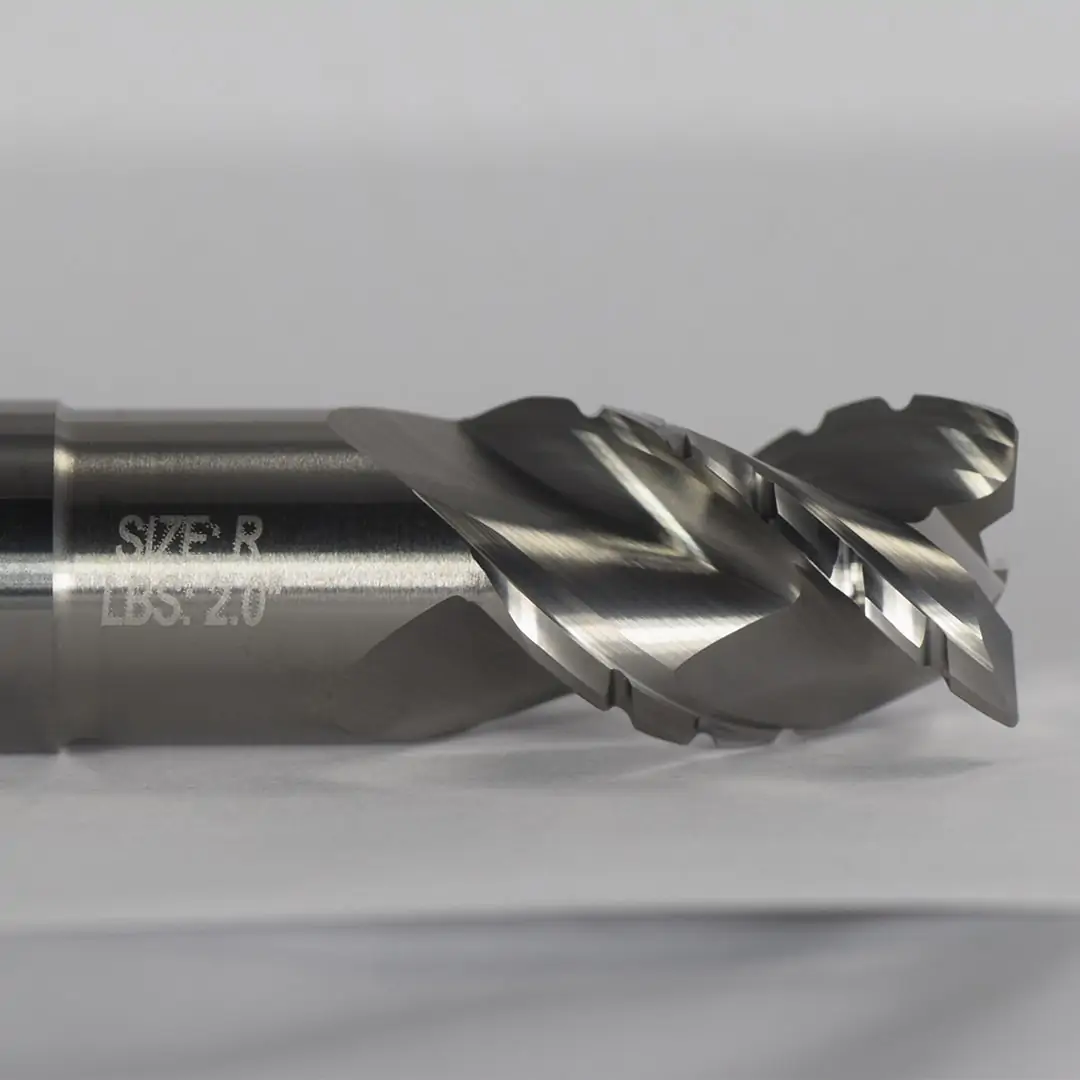
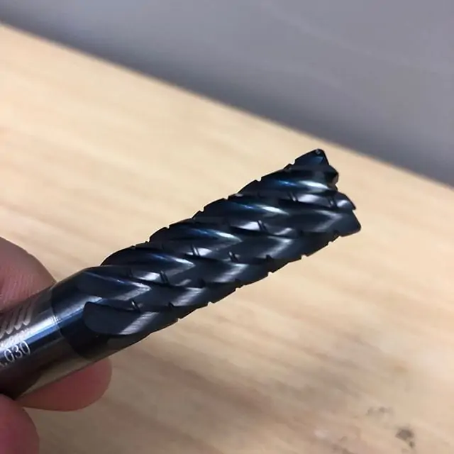
Chipbreaker End Mills feature unique notch profiles, creating a serrated cutting edge. These dividers break otherwise long, stringy chips into small, easily-managed swarf that can be cleanly evacuated from the part. But why is a chipbreaker necessary for some jobs, and not others? How does the geometry of this unique tool impact its proper running parameters? In this post, we’ll answer these questions and others to discover the very real benefits of this unique cutting geometry.
How Chipbreaker Tooling Works
As a tool rotates and its cutting edge impacts a workpiece, material is sheared off from a part, creating chips. When that cutting process is interrupted, as is the case with breaks in the cutting portion of the tool, chips become smaller in length and are thus easier to evacuate. Because the chipbreakers are offset flute-to-flute, a proper, flat surface finish is achieved as each flute cleans up any excess material left behind from previously passed flutes.
Benefits of Chipbreaker Tooling
Machining Efficiency
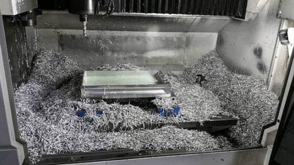
When chips are removed from the part, they begin to pile in the machine. For extensive operations, where a great deal of material is hogged out, chip accumulation can very rapidly get in the way of the spindle or part. With larger chips, accumulation occurs much faster, leaving machinists to stop their machine regularly to remove the waste. As any machinist knows, a stopped machine equates to lost money.
Prolonged Tool Life
Inefficient chip evacuation can lead to chip recutting, or when the the tool impacts and cuts chips left behind during the machining process. This adds stresses on the tool and accelerates rate of wear on the cutting edge. Chipbreaker tooling creates small chips that are easily evacuated from a part, thus minimizing the risk of recutting.
Accelerated Running Parameters
A Harvey Performance Company Application Engineer recently observed the power of a chipbreaker tool firsthand while visiting a customer’s shop in Minnesota. The customer was roughing a great amount of 4340 Steel. Running at the parameters below, the tool was able to run uninterrupted for two hours!
Chipbreaker geometry, or grooves within the cutting face of the tool, break down chips into small, manageable pieces during the machining process. This geometry can boost shop efficiency by minimizing machine downtime to clear large chips from the machining center, improve tool life by minimizing cutting forces exerted on the tool during machining, and allow for more accelerated running parameters.
Composites are a group of materials made up of at least two unique constituents that, when combined, produce mechanical and physical properties favorable for a wide array of applications. These materials usually contain a binding ingredient, known as a matrix, filled with particles or fibers called reinforcements. Composites have become increasingly popular in the Aerospace, Automotive, and Sporting Goods industries because they can combine the strength of metal, the light weight of plastic, and the rigidity of ceramics.
Unfortunately, composite materials present some unique challenges to machinists. Many composites are very abrasive and can severely reduce tool life, while others can melt and burn if heat generation is not properly controlled. Even if these potential problems are avoided, the wrong tool can leave the part with other quality issues, including delamination.
While composites such as G10 and FR4 are considered “fibrous”, composites can also be “layered,” such as laminated sheets of PEEK and aluminum. Layered composites are vulnerable to delamination, when the layers of the material are separated by a tool’s cutting forces. This yields less structurally sound parts, defeating the purpose of the combined material properties in the first place. In many cases, a single delaminated hole can result in a scrapped part.
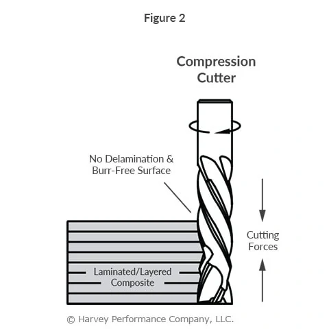
Using Compression Cutter End Mills in Composite Materials
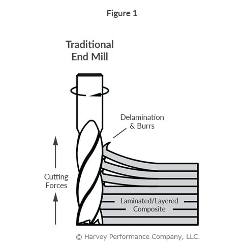
Composite materials are generally machined with standard metal cutting end mills, which generate exclusively up or down cutting forces, depending on if they have right or left hand flute geometry. These uni-directional forces cause delamination (Figure 1).
Conversely, compression cutters are designed with both up and down-cut flutes. The top portion of the length of cut, closest to the shank, has a left hand spiral, forcing chips down. The bottom portion of the length of cut, closest to the end, has a right hand spiral, forcing chips up. When cutting, the opposing flute directions generate counteracting up-cut and down-cut forces. The opposing cutting forces stabilize the material removal, which compresses the composite layers, combatting delamination on the top and bottom of a workpiece (Figure 2).
Since compression cutters do not pull up or press down on a workpiece, they leave an excellent finish on layered composites and lightweight materials like plywood. It is important to note, however, that compression cutters are suited specifically to profiling, as the benefits of the up and down-cut geometry are not utilized in slotting or plunging operations.
Something as simple as choosing a tool suited to a specific composite material can have significant effects on the quality of the final part. Consider utilizing tools optimized for different composites and operations or learn how to select the right drill for composite holemaking.
https://www.harveyperformance.com/wp-content/uploads/2017/09/Feature-Image-Compression-Cutters-IMG.jpg5251400Harvey Performance Companyhttp://www.harveyperformance.com/wp-content/uploads/2018/08/Logo_HarveyPerformanceCompany-4.pngHarvey Performance Company2017-09-12 16:00:532024-02-12 14:50:38How to Avoid Composite Delamination With Compression Cutters
Each tool holder style has its own unique properties that must be considered prior to beginning a machining operation. A secure machine-to-tool connection will result in a more profitable shop, as a poor connection can cause tool runout, pull-out, scrapped parts, damaged tools, and exhausted shop resources. An understanding of tool holders, shank features, and best practices is therefore pivotal for every machinist to know to ensure reliable tool holding.
Types of Tool Holding
The basic concept of any tool holder is to create a compression force around the cutting tool’s shank that is strong, secure, and rigid. These come in a variety of styles, each with its own spindle interface, taper for clearance, and compression force methods.
Mechanical Spindle Tightening
The most basic way in which spindle compression is generated is by simple mechanical tightening of the holder itself, or a collet within the holder. The downside of this mechanical tightening method of the spindle is its limited number of pressure points. With this style, segments of a collet collapse around the shank, and there is no uniform, concentric force holding the tool around its full circumference.
Hydraulic Tool Holders
Other methods create a more concentric pressure, gripping the tool’s shank over a larger surface area. Hydraulic tool holders create this scenario. They are tightened via a pressurized fluid inside the bore of the holder, creating a more powerful clamping force on the shank.
Shrink Fit Tool Holders
Shrink fit tool holders are another high quality tool holding mechanism. This method works by using the thermal properties of the device to expand its opening slightly larger than the shank of the tool. The tool is placed inside the holder, after which the holder is allowed to cool, contracting down close to its original size and creating a tremendous compressive force around the shank. Since the expansion of the bore in the tool holder is minuscule, a tight tolerance is needed on the shank to ensure it can fit every time. Shank diameters with h6 tolerances ensure the tool will always work properly and reliably with a shrink fit holder.
Along with choosing correctly when it comes to tool holding options, tool shanks can be modified to promote a more secure machine-to-tool connection. These modifications can include added grooves on the shank, flats, or even an altered shank surface to aid in gripping strength.
Weldon Flats
A Weldon flat can be used to create additional strength within the tool holder. The tool holder locks a tool in place with a set screw pushing on a flat area on the tool shank. Weldon flats offer a good amount of pull-out prevention due to the set screw sitting in the recessed shank flat. Often seen as an outdated method of tool holding, this method is most effective for larger, stronger tools where runout is less of a concern.
ToughGRIP Shanks
Helical Solutions offers a ToughGRIP shank modification to its customers, which works by increasing the friction of the shank – making it easier to grip for the tool holder. This modification roughs the shank’s surface while maintaining h6 shrink fit tolerance.
Haimer Safe-Lock™
In the Haimer Safe-Lock system, special drive keys in the chuck interface with grooves in the shank of the tool to prevent pull-out. The end mill effectively screws into the tool holder, which causes a connection that only becomes more secure as the tool is running. Haimer Safe-Lock™ maintains h6 shank tolerances, ensuring an even tighter connection with shrink fit holders.
Key Takeaways
While choosing a proper cutter and running it at appropriate running parameters are key factors to a machining operation, so too is the method used. If opting for an improper tool holding method, one can experience tool pull-out, tool runout, and scrapped jobs. Effective tool holding will prevent premature tool failure and allow machinists to feel confident while pushing the tool to its full potential.
Tool runout is a given in any machine shop, and can never be 100% avoided. Thus, it is important to establish an acceptable level of runout for any project, and stay within that range to optimize productivity and prolong tool life. Smaller runout levels are always better, but choice of machine and tool holder, stick-out, tool reach, and many other factors all have an influence on the amount of runout in every setup.
Defining Tool Runout
Tool runout is the measurement of how far a cutting tool, holder, or spindle rotates off of its true axis. This can be seen in low quality end mills where the cutting diameter is true to size when measured while stationary, but measures above tolerance while rotating.
The first step to minimizing runout is understanding what individual factors cause runout in every machine setup. Runout is seen in the accuracy of every cutting tool, collet, tool holder, and spindle. Every added connection between a machine and the workpiece it is cutting will introduce a higher level of runout. Each increase can add to the total runout further and further. Steps should be taken with every piece of tooling and equipment to minimize runout for best performance, increased tool life, and quality finished products.
Measuring Runout
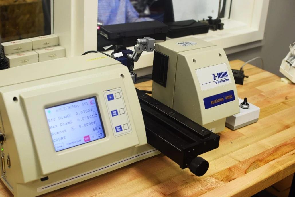
Determining the runout of your system is the first step towards finding how to combat it. Runout is measured using an indicator that measures the variation of a tool’s diameter as it rotates. This is done with either a dial/probe indicator or a laser measuring device. While most dial indicators are both portable and easy to use, they are not as accurate as the available laser indicators, and can also make a runout measurement worse by pushing on a tool. This is mostly a concern for miniature and micro-tooling, where lasers should be strictly used due to the tool’s fragile nature. Most end mill manufacturers recommend using a laser runout indicator in place of a dial indicator wherever possible.
Z-Mike laser measurement devices are common instruments used to measure levels of tool runout.
Runout should be measured at the point where a tool will be cutting, typically at the end of the tools, or along a portion of the length of cut. A dial indicator may not be plausible in these instances due to the inconsistent shape of a tool’s flutes. Laser measuring devices offer another advantage due to this fact.
High Quality Tools
The amount of runout in each component of a system, as-manufactured, often has a significant impact on the total runout of a given setup. Cutting tools all have a restriction on maximum runout allowed when manufactured, and some can have allowances of .0002” or less. This is often the value that should be strived for in a complete system as well. For miniature tooling down to .001” diameter, this measurement will have to be held to an even smaller value. As the ratio of tool runout to tool diameter becomes larger, threats of tool failure increase. As stated earlier, starting with a tool that has minimal runout is pivotal in keeping the total runout of a system to a minimum. This is runout that cannot be avoided.
Precision Tool Holders
The next step to minimizing runout is ensuring that you are using a high quality, precision tool holder. These often come in the form of shrink-fit, or press-fit tool holders offering accurate and precise tool rotation. Uniform pressure around the entire circumference of a shank is essential for reducing runout. Set screw based holders should be avoided, as they push the tool off-center with their uneven holding pressure. Collet-based tool holders also often introduce an extra amount of runout due to their additional components. Each added connection in a tool holding system allows more methods of runout to appear. Shrink-fit and press-fit tool holders are inherently better at minimizing runout due to their fewer components.
Included in your tool holding considerations should be machine tool cleanliness. Often, chips can become lodged in the spindle, and cause an obstruction between two high-precision surfaces in the system. Ensuring that your tool holder and spindle are clean and free of chips and debris is paramount when setting up for every job.
Shank Modifications
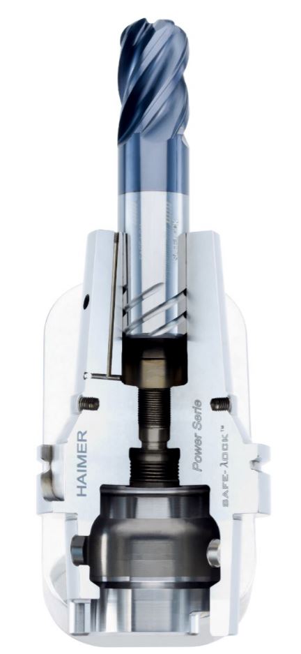
Apart from equipment itself, many other factors can contribute to an increasing amount of tool runout. These can include how long a tool is, how rigid a machine setup is, and how far a tool is hanging out of its holder. Shank modifications, along with their methods of tool holding can have a large impact. Often thought of as an older, obsolete technology, Weldon flats are found guilty of adding large amounts of runout in many shops. While many shops still use Weldon flats to ensure a secure grip on their tools, having a set screw pushing a tool to one side can push it off center, yielding very high levels of runout. Haimer Safe Lock™ is another option increasing in popularity that is a much higher performance holding technology. The Safe-Lock™ system is designed with the same tolerances as shrink fit and other high precision tool holders. It is able to minimize runout, while firmly holding a tool in place with no chance of pull-out.
The Haimer Safe-Lock™ system is one option to greatly reduce tool runout.
Runout will never be completely eliminated from a machining system. However, steps can (and should) be taken to keep it to a minimum using every method possible. Keeping a tool running true will extend tool life, increase performance, and ultimately save your shop time and money. Runout is a common concern in the metalworking industry, but it is often overlooked when it could be main issue causing part rejections and unacceptable results. Every piece of a machine tool plays a part in the resultant runout, and none should be overlooked.
The following is just one of several blog posts relevant to High Efficiency Milling. To achieve a full understanding of this popular machining method, view any of the additional HEM posts below!
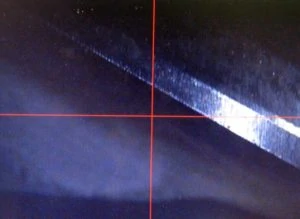
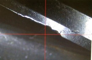
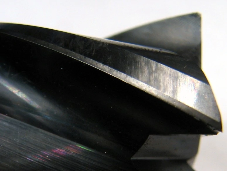
Tool wear is the breakdown and gradual failure of a cutting tool due to regular operation. Every tool will experience tool wear at some point in its life. Excessive wear will show inconsistencies and have unwanted effects on your workpiece, so it is important to avoid tool wear in order to achieve optimal end mill performance. Tool wear can also lead to failure, which in turn can lead to serious damage, rework, and scrapped parts.
An example of a tool with no wearAn example of a tool with excessive wear
To prolong tool life, identifying and mitigating the various signs of cutting tool wear is key. Both thermal and mechanical stresses cause tool wear, with heat and abrasion being the major culprits. Learning how to identify the most common types of tool wear and what causes them can help machinists remedy issues quickly and extend tool longevity.
Types of Tool Wear And Their Solutions
Abrasive Wear
The wear land is a pattern of uniform abrasion on the cutting edge of the tool, caused by mechanical abrasion from the workpiece. This dulls the cutting edge of a tool, and can even alter dimensions such as the tool diameter. At higher speeds, excessive heat becomes more of an issue, causing more damage to the cutting edge, especially when an appropriate tool coating is not used.
Utilizing Proper Tool Coatings
Using a tool coating with a high microhardness rating is crucial to avoiding abrasive wear. Microhardness ratings help determine a cutting tool’s level of wear resistance. For example, bare tungsten carbide has a Vickers Hardness (HV) ranging from 760 HV to 1740 HV while coatings such as TiN have an HV of 2213 or more. Despite facing maximum forces during cutting operations, the addition of coating on a tool significantly improves its ease of material removal due to higher hardness. When hardness in a coating is elevated wear is mitigated due to the stack up.
Coolant Usage
If the wear land becomes excessive or causes premature tool failure, reducing the cutting speed and optimizing coolant usage can help. Coolant is directed towards the cutting action of a tool during CNC operations. It prevents tool failure by countering high temperatures. Generally machinists opt for either Flood or High Pressure coolant methods. Flooding allows for low pressure chip flushing by providing lubricity. High Pressure coolant provides almost instant cooling of a part and works to evacuate chips at a faster rate. Both methods improve part finish and minimize chip recutting, which can damage a cutting tool.
High Efficiency Milling
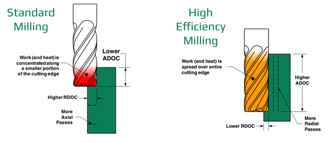
High Efficiency Milling (HEM) toolpaths can help reduce wear by spreading the work done by the tool over its entire length of cut. This prevents localized wear and will prolong tool life by using the entire cutting edge available. The image referenced below compares traditional (standard) milling and the newer HEM method. HEM evenly disperses heat across the cutting edge by employing a lower radial depth of cut (RDOC) and a higher axial depth of cut (ADOC). This reduces the likelihood of tool failure and lengthens the tool wear process.
Chipping
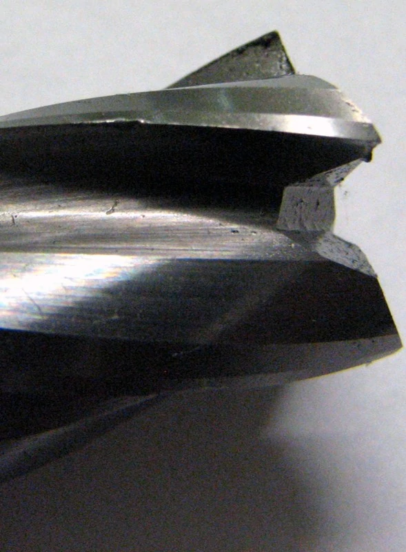
Chipping can be easily identified by a nicked or flaked edge on the cutting tool, or by examining the surface finish of a part. A poor surface finish can often indicate that a tool has experienced some sort of chipping, which can lead to eventual catastrophic tool failure if it is not caught. \When a chipped tool engages with a workpiece the cutting edges are not even leading to high and low spots within the surface finish.
Chipping is typically caused by excessive loads and shock-loading during operation, but it can also be caused by thermal cracking, another type of tool wear which is explored in further detail below.
Reduce Chatter
To counter chipping, ensure the milling operation is completely free of vibration and chatter. Chatter occurs because cutting tools experience high forces during CNC machining operations. While machinists cannot entirely avoid chatter, minimizing it prevents vibration marks and excess wear from appearing along the surface of a tool or part. Taking a look at the speeds and feeds can also help. Interrupted cuts and repeated part entry can also have a negative impact on a tool. Reducing feed rates for these situations can mitigate the risk of chipping.
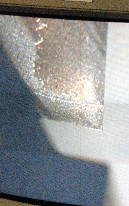
Thermal Cracking
Thermal cracking is often identified by cracks in the tool perpendicular to the cutting edge. Cracks form slowly, but they can lead to both chipping and premature tool failure.
Thermal cracking, as its name suggests, is caused by extreme temperature fluctuations during milling. Adding a proper coating to an end mill is beneficial in providing heat resistance and reduced abrasion on a tool.
HEM Toolpaths
HEM toolpaths provide excellent protection against thermal cracking. As previously mentioned, these toolpaths spread the heat across the cutting edge of the tool, reducing the overall temperature and preventing serious fluctuations in heat.
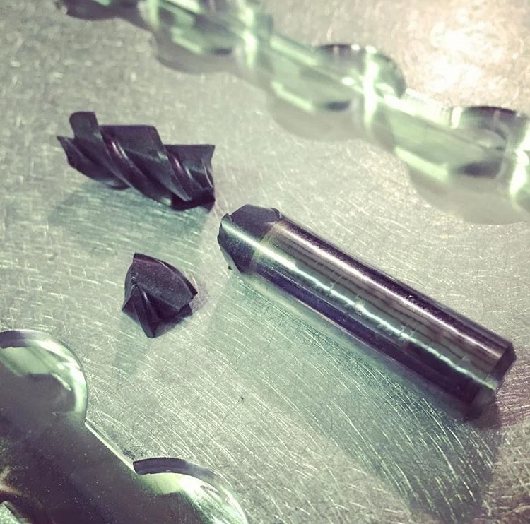
Fracture
Fracture is the complete loss of tool usage due to sudden breakage, often as a result of improper speeds and feeds, an incorrect coating, or an inappropriate depth of cut.
Optimal Tool Holding
Tool holder issues or loose work holding can also cause a fracture, as can inconsistencies in workpiece material properties. Establishing a secure connection between the tool and machine reduces the risk of tool runout and scrapped parts. Machinists generally experience improved performance in hydraulic and shrink fit tool holders compared to more mechanical tightening methods.
Adjusting the speeds, feeds, and depth of cut and checking the setup for rigidity will help to reduce fracturing. The tool’s axial engagement with a part must be appropriate in order to prevent tool deflection, especially during slotting operations. As pictured below, with increasing slot lengths comes the necessity for longer lengths of cut. Above all, you should choose a tool that offers the highest productivity and least amount of deflection.
Optimizing coolant usage can also be helpful to avoid hot spots in materials which can dull a cutting edge and cause a fracture. HEM toolpaths prevent fracture by offering a more consistent load on a tool. Shock loading is reduced, causing less stress on a tool, which lessens the likelihood of breakage and increases tool life.
It is important to monitor tools and keep them in good, working condition to avoid downtime and save money. Wear is caused by both thermal and mechanical forces, which can be mitigated by running with appropriate running parameters and HEM toolpaths to spread wear over the entire length of cut. While every tool will eventually experience some sort of tool wear, the effects can be delayed by paying close attention to speeds and feeds and depth of cut. Preemptive action should be taken to correct issues before they cause complete tool failure.
https://www.harveyperformance.com/wp-content/uploads/2017/07/Feature-Image-Tool-Wear-IMG.jpg5251400Harvey Performance Companyhttp://www.harveyperformance.com/wp-content/uploads/2018/08/Logo_HarveyPerformanceCompany-4.pngHarvey Performance Company2017-07-11 16:30:432023-11-17 14:56:39How to Avoid 4 Major Types of Tool Wear
The following is just one of several blog posts relevant to High Efficiency Milling. To achieve a full understanding of this popular machining method, view any of the additional HEM posts below!
Every machining operation entails a radial and axial depth of cut strategy. Radial depth of cut (RDOC), the distance a tool is stepping over into a workpiece; and Axial depth of cut (ADOC), the distance a tool engages a workpiece along its centerline, are the backbones of machining. Machining to appropriate depths – whether slotting or peripheral milling (profiling, roughing, and finishing), is vital to your machining success (Figure 1).
Below, you will be introduced to the traditional methods for both peripheral milling and slotting. Additionally, High Efficiency Milling (HEM) strategies – and appropriate cutting depths for this method – will be explained.
Quick Definitions:
Radial Depth of Cut (RDOC): The distance a tool is stepping over into a workpiece. Also referred to as Stepover, Cut Width, or XY.
Axial Depth of Cut (ADOC): The distance a tool engages a workpiece along its centerline. Also referred to as Stepdown, or Cut Depth.
Peripheral Milling: An application in which only a percentage of the tool’s cutter diameter is engaging a part.
Slotting: An application in which the tool’s entire cutter diameter is engaging a part.
High Efficiency Milling (HEM): A newer machining strategy in which a light RDOC and heavy ADOC is paired with increased feed rates to achieve higher material removal rates and decreased tool wear.
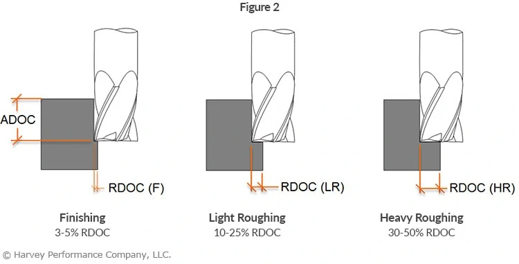
Peripheral Milling Styles and Appropriate RDOC
The amount a tool engages a workpiece radially during peripheral milling is dependent upon the operation being performed (Figure 2). In finishing applications, smaller amounts of material are removed from a wall, equating to about 3-5% of the cutter diameter per radial pass. In heavy roughing applications, 30-50% of the tool’s cutter diameter is engaged with the part. Although heavy roughing involves a higher RDOC than finishing, the ADOC is most often smaller than for finishing due to load on the tool.
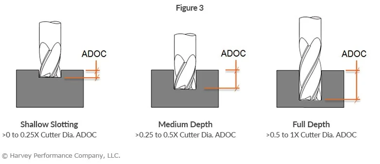
Slotting Styles and Appropriate ADOC Engagement
The amount a tool engages a part axially during a slotting operation must be appropriate for the tool being used (Figure 3). Using an inappropriate approach could lead to tool deflection and damage, and poor part quality.
End mills come in various length of cut options, as well as numerous reached options. Choosing the tool that allows the completion of a project with the least deflection, and highest productivity, is critical. As the ADOC needed to slot can be lower, a stub length of cut is often the strongest and most appropriate tool choice. As slot depths increase, longer lengths of cut become necessary, but reached tooling should be used where allowable.
Depth of Cut Strategy for High Efficiency Milling (HEM)
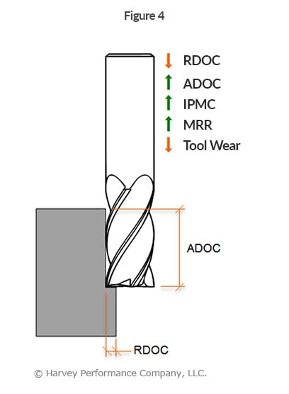
Pairing a light RDOC and heavy ADOC with high performance toolpaths is a machining strategy known as High Efficiency Milling or HEM. With this machining style, feed rates can be increased and cuts are kept uniform to evenly distribute stresses across the cutting portion of the tool, prolonging tool life.
HEM involves using 7-30% of the tool diameter radially and up to twice the cutter diameter axially, paired with increased feed rates (Figure 4). Accounting for chip thinning, this combination of running parameters can result in noticeably higher metal removal rates (MRR). Modern CAM software often offers a complete high performance solution with built-in features for HEM toolpaths. These principals can also be applied to trochoidal toolpaths for slotting applications.
https://www.harveyperformance.com/wp-content/uploads/2017/06/Feature-Image-Depth-of-Cut-IMG.jpg5251400Harvey Performance Companyhttp://www.harveyperformance.com/wp-content/uploads/2018/08/Logo_HarveyPerformanceCompany-4.pngHarvey Performance Company2017-06-15 08:30:062023-10-12 08:55:45Diving Into Depth of Cut: Peripheral, Slotting, & HEM Approaches
In today’s manufacturing industry, the reach necessary for many complex parts is pushing the boundaries of plausibility. Deep cavities and complex side milling operations are typical to the mold, tool, and die industry but are also quite common in many machining applications requiring angled walls. Fortunately, many long reach applications include angled walls extending into deep pockets and mold cavities. These slight angles afford machinists the opportunity to gain the necessary strength of tapered reach tool designs.
Increased Tool Performance & Productivity
The benefits of tapered end mills become clear when considering the increase in cross-sectional area compared to tools with straight reaches. Generally speaking, the larger a tool’s diameter is, the stronger it will be. A tool with a tapered neck will offer an increasing cross section, resulting in less tool deflection and increased strength over straight reach options.
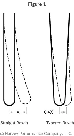
When considering an end mill with a straight reach versus the same end mill with a slightly tapered reach, there are clear gains in tool performance and productivity. With just a 3° angle per side, feed rates may be increased by an average of 10% over a straight neck. In long-run jobs, or long run-time operations, this can offer a significant reduction in production time and cost. The same 3° angle also affords a tool as much as 60% less deflection than a straight neck tool (Figure 1). A taper as small as half a degree also provides a 10% decrease in deflection even for shorter reaches. This reduction in deflection results in less chatter, better finish, and ultimately a higher quality product.
Tapered End Mills vs. Straight End Mills
Tapered Reach
Compared with straight reach end mills, tapered reach end mills have the following pros and cons:
• Reduced clearance • Not plausible for use in certain situations
Tapered Length of Cut
End mills with a tapered length of cut experience the following pros and cons when compared with end mills with a straight length of cut:
Pros:
• Easier to create flat tapered walls on 3-axis machines • Avoid witness marks caused by multiple passes with other tools • Better, more consistent finish
Cons:
• “Single-use” tools, suited only to specific wall angles • Inconsistent cutting diameter can complicate optimizing speeds and feeds
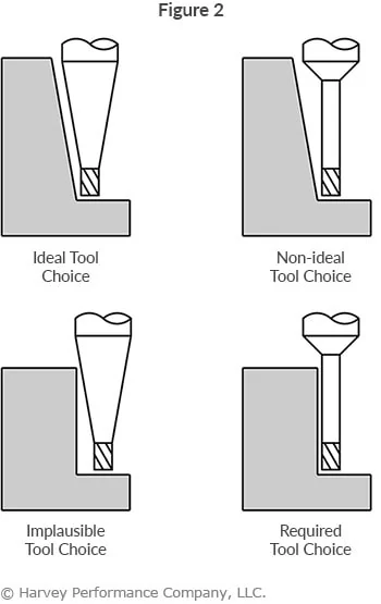
Despite the potential significant benefits of even a slight taper, it is important to note that tapered end mills are not a plausible choice for every job. Depending on the wall angle of your part, a tapered end mill can interfere with the work piece in situations where a straight tool would not. In Figure 2 below, the top two images show the ideal use of a tapered tool, while the bottom two images show when using a tapered end mill is implausible and a straight tool is necessary. Where clearances allow, an end mill with the largest possible tapered reach should be chosen for optimal tool performance.
Even a slight taper offers an increase in tool performance over the same tool with a straight neck. With added strength and reduced deflection, the benefits of a tapered end mill can be significant, and extend to a much broader range of industries and applications beyond just mold tool and die.
Tapered Reach Tooling Interference Charts
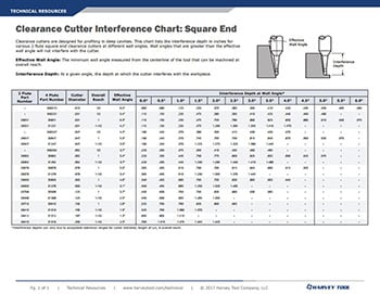
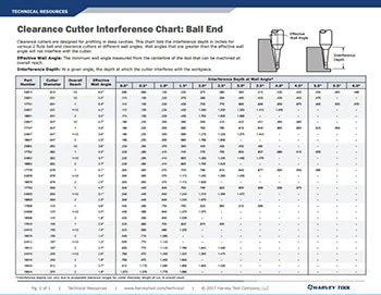
Where clearances allow, an end mill with the largest possible tapered reach angle should be chosen to allow for optimal tool performance. Refer to Harvey Tool’s interference charts for our Square and Ball clearance cutters to ensure that you pick the ideal tapered end mill based on the parameters of your operation.
https://www.harveyperformance.com/wp-content/uploads/2017/05/Feature-Image-Tapered-End-Mills-IMG.jpg5251400Tom Pylehttp://www.harveyperformance.com/wp-content/uploads/2018/08/Logo_HarveyPerformanceCompany-4.pngTom Pyle2017-05-30 16:00:562023-10-12 08:49:26Increase Productivity With Tapered End Mills
During the milling process, and especially during corner engagement, tools undergo significant variations in cutting forces. One common and difficult situation is when a cutting tool experiences an “inside corner” condition. This is where the tool’s engagement angle significantly increases, potentially resulting in poor performance.
Challenges of Corner Engagement
Engaging corners improperly can lead to various issues, affecting both performance and quality. Some common challenges include:
Chatter: – visible imperfections in corner finishes
Deflection – detected by unwanted wall taper measurements
Strange cutting sound – tool squawking or chirping in the corners
Tool breakage/failure or chipping – resulting from excessive stress or improper handling
Least Effective Approach (Figure 1)
Generating an inside part radius that matches the radius of the tool at a 90° direction range is not a desirable approach to machining a corner. In this approach, the tool experiences extra material to cut (dark gray), an increased engagement angle, and a direction change. As a result, issues including chatter, tool deflection/ breakage, and poor surface finish may occur.
Feed rate may need to be lessened depending on the “tool radius-to-part radius ratio.”
More Effective Approach (Figure 2)
Generating an inside part radius that matches the radius of the tool with a sweeping direction change is a more desirable approach for corner engagement. The smaller radial depths of cut (RDOC) in this example help to manage the angle of engagement, but at the final pass, the tool will still experience a very high engagement angle. Common results of this approach will be chatter, tool deflection/breakage and poor surface finish.
Feed rate may need to be reduced by 30-50% depending on the “tool radius-to-part radius ratio.”
Most Effective Approach For Corner Engagement (Figure 3)
Generating an inside part radius with a smaller tool and a sweeping action creates a much more desirable machining approach. The manageable RDOC and smaller tool diameter allow for management of the tool engagement angle, higher feed rates and better surface finishes. As the cutter reaches full radial depth, its engagement angle will increase, but the feed reduction should be much less than in the previous approaches.
Feed rate may need to be heightened depending on the “tool-to-part ratio.” Utilize tools that are smaller than the corner you are machining.
Corner engagement is a critical aspect of machining that demands attention to detail and strategic planning. By implementing effective techniques and leveraging appropriate tools, manufacturers can overcome challenges associated with corner machining and achieve superior results.
https://www.harveyperformance.com/wp-content/uploads/2017/05/Featured-Image-Corner-Engagement-IMG.jpg5251400Harvey Performance Companyhttp://www.harveyperformance.com/wp-content/uploads/2018/08/Logo_HarveyPerformanceCompany-4.pngHarvey Performance Company2017-05-15 07:00:142024-04-16 14:18:21Corner Engagement: How to Machine Corners
While they are specialty tools, dovetail style cutters have a broad range of applications. Dovetails are typically used to cut O-ring grooves in fluid and pressure devices, industrial slides and detailed undercutting work. Dovetail cutters have a trapezoidal shape—like the shape of a dove’s tail. General purpose dovetails are used to undercut or deburr features in a workpiece. O-ring dovetail cutters are held to specific standards to cut a groove that is wider at the bottom than the top. This trapezoidal groove shape is designed to hold the O-ring and keep it from being displaced.
The dovetail cutter’s design makes it fragile, finicky, and highly susceptible to failure. In calculating job specifications, machinists frequently treat dovetail cutters as larger than they really are because of their design, leading to unnecessary tool breakage. They mistake the tool’s larger end diameter as the critical dimension when in fact the smaller neck diameter is more important in making machining calculations.
As the tools are downsized for micro-applications, their unique shape requires special considerations. When machinists understand the true size of the tool, however, they can minimize breakage and optimize cycle time.
Miniature Matters – Micro Dovetailing
As the trend towards miniaturization continues, more dovetailing applications arise along with the need for applying the proper technique when dovetailing microscale parts and features. However, there are several common misunderstandings about the proper use of dovetails, which can lead to increased tool breakage and less-than-optimal cycle times.
There are seven common mistakes made when dovetailing and several strategies for avoiding them:
1. Not Taking Advantage of Drop Holes
Many O-ring applications allow for a drop hole to insert the cutter into the groove. Take advantage of a drop hole if the part design allows it, as it will permit usage of the largest, most rigid tool possible, minimizing the chance of breakage (Figure 1).
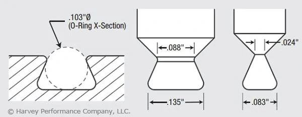
Figure 1. These pictured tools are designed to mill a groove for a Parker Hannifin O-ring groove No. AS568A-102 (left). These O-rings have cross sections of 0.103″. There is a large variation in the tools’ neck diameters. The tool at right, with a neck diameter of 0.024″, is for applications without a drop hole, while the other tool, with a neck diameter of 0.088″, is for drop-hole applications. The drop-hole allowance allows application of the more rigid tool.
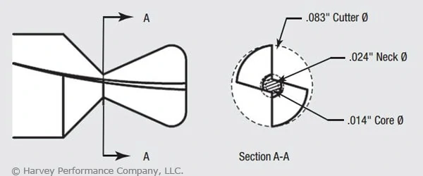
2. Misunderstanding a Dovetail’s True Neck Diameter.
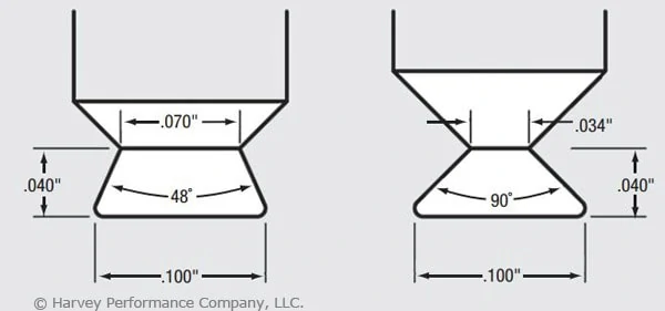
The dovetail’s profile includes a small neck diameter behind a larger end-cutting diameter. In addition, the flute runs through the neck, further reducing the tool’s core diameter. (In the example shown in Figure 2, this factor produces a core diameter of just 0.014″.) The net result is that an otherwise larger tool becomes more of a microtool. The torque generated by the larger diameter is, in effect, multiplied as it moves to the narrower neck diameter. You must remember that excess stress may be placed on the tool, leading to breakage. Furthermore, as the included angle of a dovetail increases, the neck diameter and core diameter are further reduced. O-ring dovetail cutters have an included angle of 48°. Another common included angle for general purpose dovetails is 90°. Figure 3 illustrates how two 0.100″-dia. dovetail tools have different neck diameters of 0.070″ vs. 0.034″ and different included angles of 48° vs. 90°.
Figure 2. The dovetail tool pictured is the nondrop-hole example from Figure 1. The cross section illustrates the relationship between the end diameter of the tool (0.083″) and the significantly smaller core diameter (0.014″). Understanding this relationship and the effect of torque on a small core diameter is critical to developing appropriate dovetailing operating parameters.Figure 3: These dovetail tools have the same end diameter but different neck diameters (0.070″ vs. 0.034″) and different included angles (48° vs. 90°).
3. Calculating Speeds and Feeds from the Wrong Diameter.
Machinists frequently use the wrong tool diameter to calculate feed rates for dovetail cutters, increasing breakage. In micromachining applications where the margin for error is significantly reduced, calculating the feed on the wrong diameter can cause instantaneous tool failure. Due to the angular slope of a dovetail cutter’s profile, the tool has a variable diameter. While the larger end diameter is used for speed calculations, the smaller neck diameter should be used for feed calculations. This yields a smaller chip load per tooth. For example, a 0.083″-dia. tool cutting aluminum might have a chip load of approximately 0.00065 IPT, while a 0.024″-dia. mill cutting the same material might have a 0.0002-ipt chip load. This means the smaller tool has a chip load three times smaller than the larger tool, which requires a significantly different feed calculation.
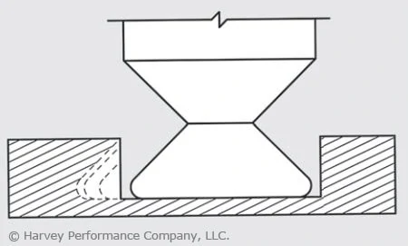
4. Errors in Considering Depth of Cut.
In micromachining applications, machinists must choose a depth of cut (DOC) that does not exceed the limits of the fragile tool. Typically, a square end mill roughs a slot and the dovetail cutter then removes the remaining triangular-shaped portion. As the dovetail is stepped over with each subsequent radial cut, the cutter’s engagement increases with each pass. A standard end mill allows for multiple passes by varying the axial DOC. However, a dovetail cutter has a fixed axial DOC, which allows changes to be made only to the radial DOC. Therefore, the size of each successive step-over must decrease to maintain a more consistent tool load and avoid tool breakage (Figure 4).
Figure 4: In microdovetailing operations, increased contact requires diminishing stepover to maintain constant tool load.
5. Failing to Climb Mill.
Although conventional milling has the benefit of gradually loading the tool, in low-chip load applications (as dictated by a dovetail cutter’s small neck diameter) the tool has a tendency to rub or push the workpiece as it enters the cut, creating chatter, deflection and premature cutting edge failure. The dovetail has a long cutting surface and tooth pressure becomes increasingly critical with each pass. Due to the low chip loads encountered in micromachining, this approach is even more critical to avoid rubbing. Although climb milling loads the tool faster than conventional milling, it allows the tool to cut more freely, providing less deflection, finer finish and longer cutting-edge life. As a result, climb milling is recommended when dovetailing.
6. Improper Chip Flushing.
Because dovetail cuts are typically made in a semi-enclosed profile, it is critical to flush chips from the cavity. In micro-dovetailing applications, chip packing and recutting due to poorly evacuated chips from a semi-enclosed profile will dull the cutter and lead to premature tool failure. In addition to cooling and lubricating, a high-pressure coolant effectively evacuates chips. However, excessive coolant pressure placed directly on the tool can cause tool vibration and deflection and even break a microtool before it touches the workpiece. Take care to provide adequate pressure to remove chips without putting undue pressure on the tool itself. Specific coolant pressure settings will depend upon the size of the groove, the tool size and the workpiece material. Also, a coolant nozzle on either side of the cutter cleans out the groove ahead of and behind the cutter. An air blast or vacuum hose could also effectively remove chips.
7. Giving the Job Away.
As discussed in item number 3, lower chip loads result in significantly lower material-removal rates, which ultimately increase cycle time. In the previous example, the chip load was three times smaller, which would increase cycle time by the same amount. Cycle time must be factored into your quote to ensure a profitable margin on the job. In addition to the important micro-dovetailing considerations discussed here, don’t forget to apply the basics critical to all tools. These include keeping runout low, using tools with application-specific coatings and ensuring setups are rigid. All of these considerations become more important in micro-applications because as tools get smaller, they become increasingly fragile, decreasing the margin of error. Understanding a dovetail cutter’s profile and calculating job specifications accordingly is critical to a successful operation. Doing so will help you reach your ultimate goal: bidding the job properly and optimizing cycle time without unnecessary breakage.
This article was written by Peter P. Jenkins of Harvey Tool Company, and it originally appeared in MicroManufacturing Magazine.
Finishing cuts are used to complete a part, achieving its final dimensions within tolerance and its required surface finish. Most often an aesthetic demand and frequently a print specification, surface finish can lead to a scrapped part if requirements are not met. Meeting finish requirements in-machine has become a major point of improvement in manufacturing, as avoiding hand-finishing can significantly reduce costs and cycle times.
Common Finishing Problems
Burrs
Scallop marks
Chatter Marks
Factors That Influence Part Finish
Specific material and hardness
Cutting tool speeds & feeds
Tool design and deployment
Tool projection and deflection
Tool-to-workpiece orientation
Rigidity of workholding
Coolant and lubricity
Final-pass depth of cut
Finishing Problem Solutions
Tools with high helix angles and flute counts work best for finishing operations. Softer materials show great results with higher helices, while harder materials can benefit greatly from increased flute counts.
Increase your RPM and lower your IPT (Figure 2).
Ensure that tool runout is extremely minimal.
Use precision tool holders that are in good condition, are undamaged, and run true.
Opt for a climb milling machining method.
Use tooling with Variable Pitch geometry to help reduce chatter.
A proper radial depth of cut (RDOC) should be used. For finishing operations, the RDOC should be between 2 and 5 percent of the tool’s Cutter Diameter.
For long reach walls, use reduced neck tooling which help to minimize deflection (Figure 3).
Extreme contact finishing (3x cutter diameter), may require a 50% feed rate reduction.
Common Surface Finish Nomenclature
Ra = Roughness average Rq = RMS (Root Mean Square) = Ra x 1.1 Rz = Ra x 3.1
https://www.harveyperformance.com/wp-content/uploads/2017/04/Feature-Image-Part-Finish-Reference-Guide-IMG.jpg5251400Harvey Performance Companyhttp://www.harveyperformance.com/wp-content/uploads/2018/08/Logo_HarveyPerformanceCompany-4.pngHarvey Performance Company2017-04-25 12:30:242022-06-08 09:21:37How to Avoid Common Part Finish Problems
We use cookies to ensure that we give you the best experience on our website. If you continue to use this site we will assume that you are happy with it.Ok


Share this entry