Simplify Your Cutting Tool Orders
With the launch of the new Helical Solutions website, Harvey Performance Company is proud to introduce a new way to order Helical cutting tools. Now, users of our new website are able to send a “shopping cart” of Helical tools they’re interested in directly to their distributor to place an order, or share it with a colleague. Let’s dive into the details about this functionality and learn how you can take advantage of the time savings associated with sending a “shopping cart” to your distributor for simplified ordering.
Get Started with a HelicalTool.com Account
First, you must create an account on HelicalTool.com. Having an account on the Helical website allows you to save and edit “shopping carts,” which can be sent to a distributor to place an order; choose a preferred distributor; auto-fill your information in any important forms; and to manage your shipping information.

Now that you have an account, it is time to start creating your first “shopping cart.”
Creating a “Shopping Cart”
To begin creating a new shopping cart, simply click on the “My Carts” text in the top right menu. This will take you to the management portal, where you can add a new “shopping cart” by selecting “Create New Shopping Cart.”

Once complete, you can name your “shopping cart” anything you would like. One example might be creating a collection of tools for each of your jobs, or for different machines in the shop. In this case, we will name it “Aluminum Roughing Job.” You can create as many different “shopping carts” as you would like; they’ll never be removed from your account unless you choose to delete them, allowing you to go back to past tooling orders whenever you’d like.
Now that you have a “shopping cart” created, it is time to start adding tools to it!
Adding Tools to Your Helical “Shopping Cart”
There are multiple ways to add tooling to your “shopping cart,” but the easiest method is by heading to a product table. In this example, we will be adding tooling from our 3 Flute, Corner Radius – 35° Helix product line. We want to add a quantity of 5 of EDP #59033 to our “shopping cart.” To do this, simply click on the “Add To Cart” icon located in the table row next to pricing and tool descriptions. This will open up a small window where we can manage our selection. The first step will be to choose which “shopping cart” we want to add this tool to, so we will select our “Aluminum Roughing Job” collection.

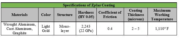
Since this tool is offered uncoated and Zplus coated, we need to select which option we would like from the drop down menu. For this example, we will select the Zplus coated tool. Now, we simply need to update our quantity to “5”, and click “Add To Cart.” That tool will now appear in your “shopping cart” in the quantity selected.
If you need more information on a tool, you can click on an EDP number to be brought to the tool details page, where you can also add that EDP to your collection.
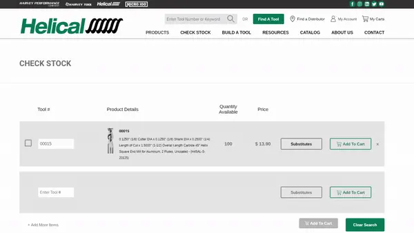
If you know the EDP number you need and want to check stock levels, use our Check Stock feature to check quantities on hand, and then add the tools to your “shopping cart” right from the Check Stock page.
Now, it is time to send the “shopping cart” to place an order with your distributor!
Placing An Order With Your Distributor
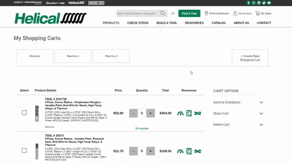
Once you have completed adding tools to your Helical “shopping cart,” navigate back to the My Carts page to review it. From here, you can update quantities, see list pricing, and access valuable resources.
On the right side of the My Cart screen, you will see an option to “Send to Distributor.” Click on the text to expand the drop down. If you have previously added a preferred distributor from your account page and they are participating in our Shopping Cart Program, you will see their information in this area.
If you have not yet selected a preferred distributor, select “Update My Distributor.” This will bring you to a new page where you can select your state and see all participating distributors in your area. Select one distributor as your preferred distributor, and then head back to the My Cart page.
Now that you have a distributor selected, you can do a final review of the “shopping cart,” and then simply click “Send Cart.” This will send an email order directly to your distributor with all of your shipping information, your list of tools and requested quantities, and your contact information. You will also receive a copy of this email for your records.
Within 1 business day, the distributor will follow up with you to confirm the order, process payment, and get the tools shipped out and on the way to your shop. No more phone calls or emails – just a single click, and your order is in the hands of our distributor partners.
To get started with this exciting new way to shop for Helical cutting tools, click here to begin creating an account on HelicalTool.com!