Slaying Stainless Steel: Machining Guide
Stainless steel can be as common as Aluminum in many shops, especially when manufacturing parts for the aerospace and automotive industries. It is a fairly versatile material with many different alloys and grades which can accommodate a wide variety of applications. However, milling steel can also be immensely difficult. Stainless steels are notorious end mill assassins, so dialing in your speeds and feeds and selecting the proper tool is essential for machining success.

Material Properties
Stainless steels are high-alloy steels with superior corrosion resistance to carbon and low-alloy steels. This is largely due to their high chromium content, with most grades of stainless steel alloys containing at least 10% of the element.
Stainless steel can be broken out into one of five categories: Austenitic, Ferritic, Martensitic, Precipitation Hardened (PH), and Duplex. In each category, there is one basic, general purpose alloy. From there, small changes in composition are made to the base in order to create specific properties for various applications.
For reference, here are the properties of each of these groupings, as well as a few examples of the popular grades and their common uses.
| Category | Properties | Popular Grades | Common Uses |
| Austenitic | Non-magnetic, outstanding corrosion and heat resistance. | 304, 316 | Food processing equipment, gutters, bolts, nuts, and other fasteners. |
| Ferritic | Magnetic, lower corrosion and heat resistance than Austenitic. | 430, 446 | Automotive parts and kitchen appliances. |
| Martensitic | Magnetic, moderate corrosion resistance – not for severe corrosion. | 416, 420, 440 | Knives, firearms, surgical instruments, and hand tools. |
| Precipitation Hardened (PH) | Strongest grade, heat treatable, severe corrosion resistance. | 17-4 PH, 15-5 PH | Aerospace components. |
| Duplex | Stronger mixture of both Austenitic and Ferritic. | 244, 2304, 2507 | Water treatment plants, pressure vessels. |
Tool Selection
Choosing the correct tooling for your application is crucial when machining stainless steel. Roughing, finishing, slotting, and high efficiency milling toolpaths can all be optimized for stainless steel by choosing the correct style of end mill.
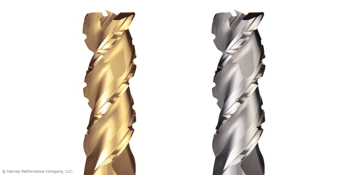
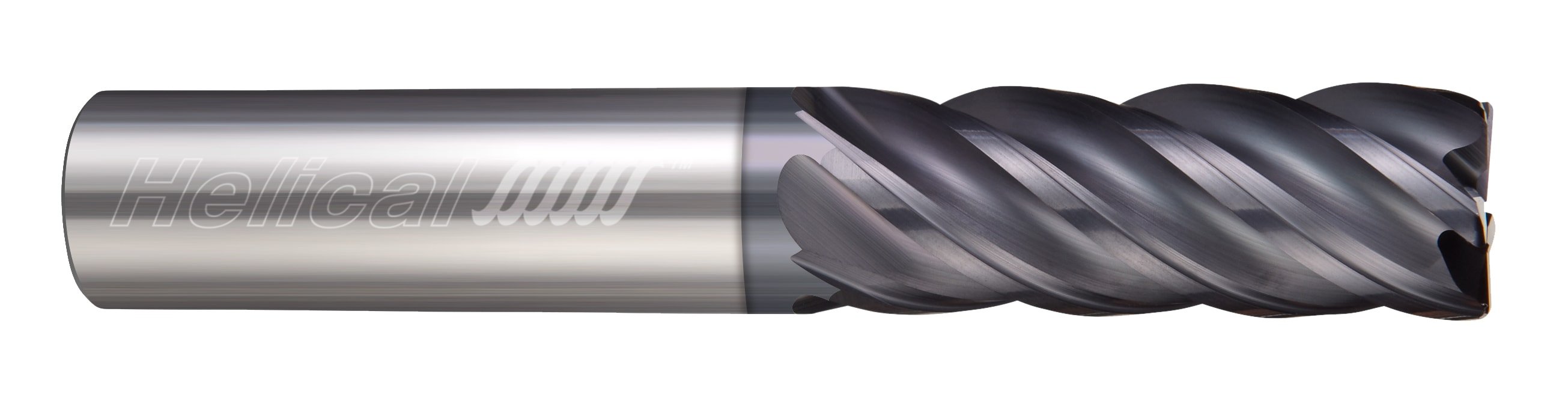
Traditional Roughing
For traditional roughing, a 4 or 5 flute end mill is recommended. 5 flute end mills will allow for higher feed rates than their 4 flute counterparts, but either style would work well for roughing applications. Below is an excellent example of traditional roughing in 17-4 Stainless Steel.
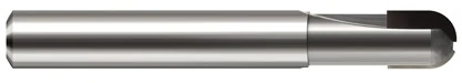
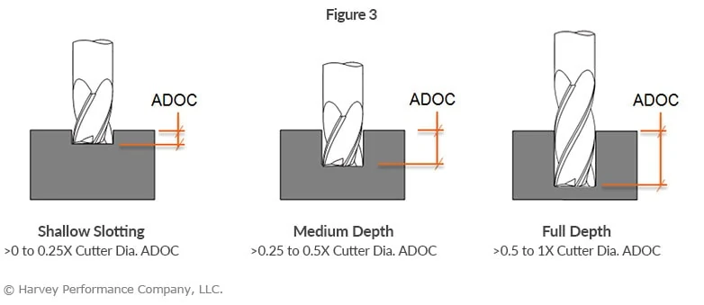
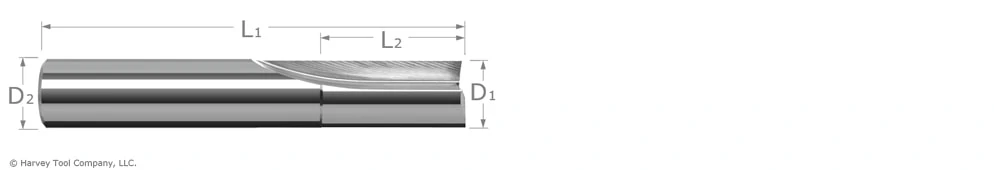
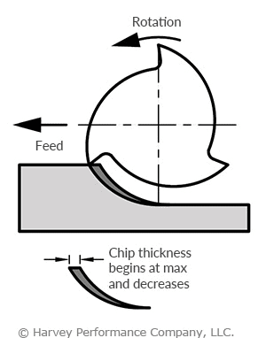
Slotting
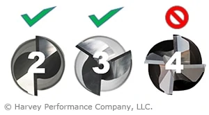
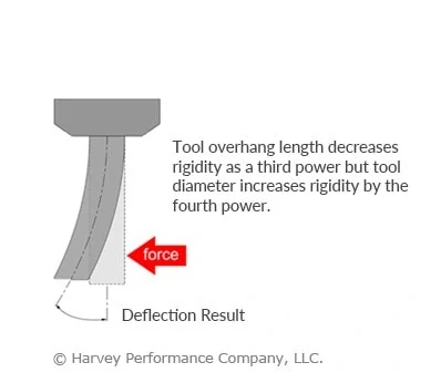
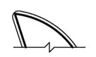
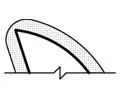
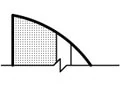
The axial engagement of a tool in a slotting operation should be suitable for the specific tool employed, as depicted in Figure 3. Employing an unsuitable method may result in tool deflection, potential damage, and compromised part quality. Chip evacuation is going to be key for slotting in stainless steel. For this reason, 4 flute tools are the best choice because the lower flute count allows for more efficient chip evacuation. Tools with chipbreaker geometry also make for effective slotting in stainless steel, as the smaller chips are easier to evacuate from the cut.
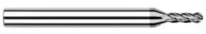
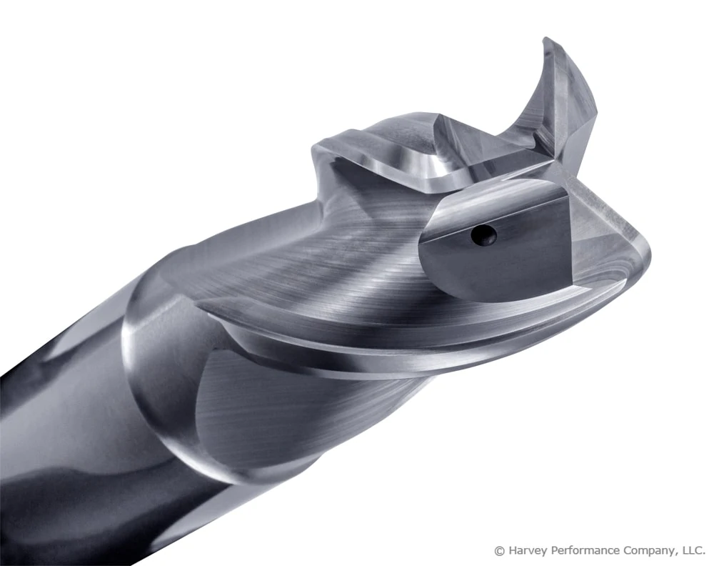
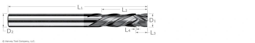
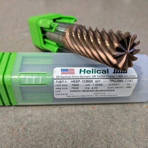
Finishing
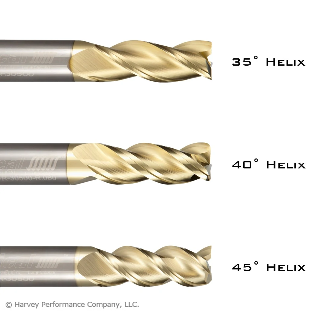
When finishing stainless steel parts, a high flute count and/or high helix is required for the best results. Finishing end mills for stainless steel will have a helix angle over 40 degrees, and a flute count of 5 or more. For more aggressive finishing toolpaths, flute count can range from 7 flutes to as high as 14. Below is a great example of a finishing run in 17-4 Stainless Steel.
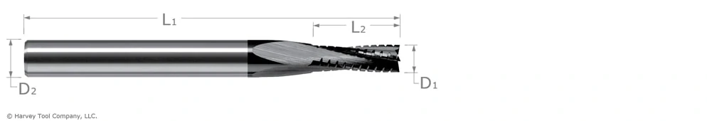
High Efficiency Milling
High Efficiency Milling (HEM) can be a very effective machining technique in stainless steels if the correct tools are selected. Chipbreaker roughers would make an excellent choice, in either 5 or 7 flute styles, while standard 5-7 flute, variable pitch end mills can also perform well in HEM toolpaths.
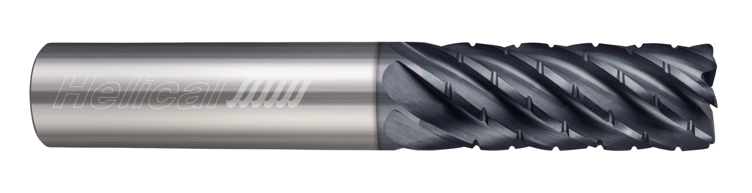
HEV-5
Helical Solutions offers the HEV-5 end mill, which is an extremely versatile tool for a variety of applications. The HEV-5 excels in finishing and HEM toolpaths, and also performs well above average in slotting and traditional roughing. Available in square, corner radius, and long reach styles, this well-rounded tool is an excellent choice to kickstart your tool crib and optimize it for stainless steel machining.
Running Parameters
While tool selection is a critical step to more effective machining, dialing in the proper running parameters is equally important. There are many factors that go into determining the running parameters for stainless steel machining, but there are some general guidelines to follow as a starting point.
Generally speaking, when machining stainless steels a SFM of between 100-350 is recommended, with a chip load ranging between .0005” for a 1/8” end mill up to .006” for a 1” end mill. A full breakdown of these general guidelines is available here.
Machining Advisor Pro
Machining Advisor Pro is a cutting edge resource designed to precisely calculate running parameters for high performance Helical Solutions end mills in materials like stainless steel, aluminum, and much more. Simply input your tool, your exact material grade, and machine setup and Machining Advisor Pro will generate fully customizable running parameters. This free resource allows you to push your tools harder, faster, and smarter to truly dominate the competition.

Dial In Your Stainless Steel Machining Application With Helical Solutions’ Machining Advisor Pro
In Conclusion
Stainless steel machining doesn’t have to be hard. By identifying the proper material grade for each part, selecting the perfect cutting tool, and optimizing running parameters, headaches from milling steel can become a thing of the past.
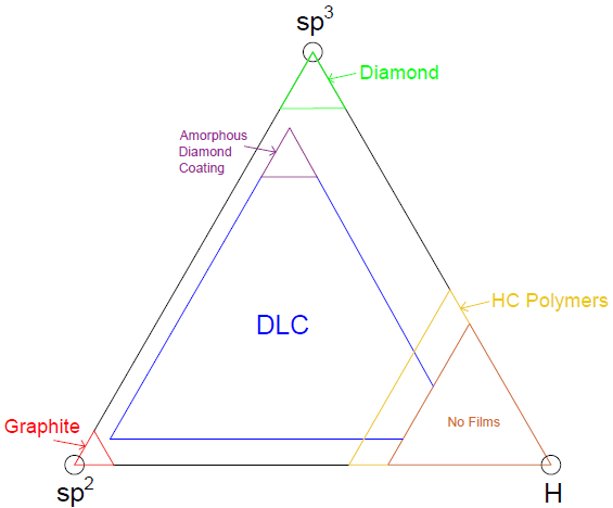
 How Diamond Coatings Differ