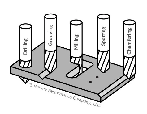
Selecting the Right Harvey Tool Miniature Drill
Among Harvey Tool’s expansive holemaking solutions product offering are several different types of miniature drill options and their complements. Options range from Miniature Spotting Drills to Miniature High Performance Drills – Deep Hole – Coolant Through. But which tools are appropriate for the hole you aim to leave in your part? Which tool might your current carousel be missing, leaving efficiency and performance behind? Understanding how to properly fill your tool repertoire for your desired holemaking result is the first step toward achieving success.
Pre-Drilling Considerations
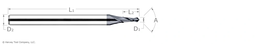
Miniature Spotting Drills
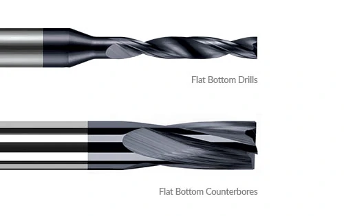
Depending on the depth of your desired machined hole and its tolerance mandates, as well as the surface of the machine you will be drilling, opting first for a Miniature Spotting Drill might be beneficial. This tool pinpoints the exact location of a hole to prevent common deep-hole drilling mishaps such as walking, or straying from a desired path. It can also help to promote accuracy in instances where there is an uneven part surface for first contact. Some machinists even use Spotting Drills to leave a chamfer on the top of a pre-drilled hole. For extremely irregular surfaces, however, such as the side of a cylinder or an inclined plane, a Flat Bottom Drill or Flat Bottom Counterbore may be needed to lessen these irregularities prior to the drilling process.
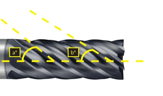
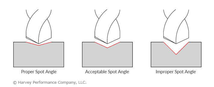
Tech Tip: When spotting a hole, the spot angle should be equal to or wider than the angle of your chosen miniature drill. Simply, the miniature drill tip should contact the part before its flute face does.
Selecting the Right Miniature Drill
Harvey Tool stocks several different types of miniature drills, but which option is right for you, and how does each drill differ in geometry?
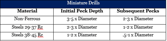
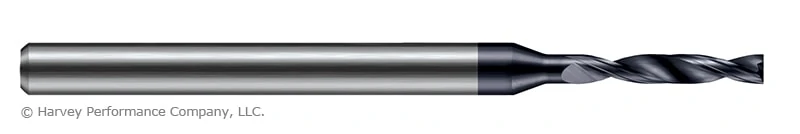
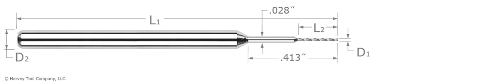
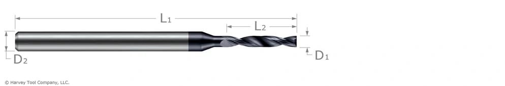
Miniature Drills
Harvey Tool Miniature Drills are popular for machinists seeking flexibility and versatility with their holemaking operation. Because this line of tooling is offered uncoated in sizes as small as .002” in diameter, machinists no longer need to compromise on precision to reach very micro sizes. Also, this line of tooling is designed for use in several different materials where specificity is not required.
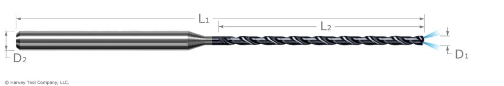
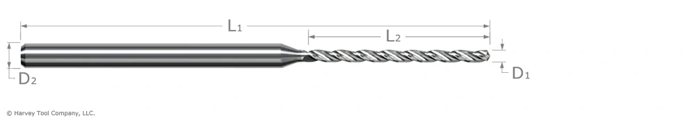
Miniature High Performance Drills – Deep Hole – Coolant Through
For situations in which chip evacuation may be difficult due to the drill depth, Harvey Tool’s Deep Hole – Coolant Through Miniature Drills might be your best option. The coolant delivery from the drill tip will help to flush chips from within a hole, and prevent heeling on the hole’s sides, even at depths up to 20 multiples of the drill diameter.
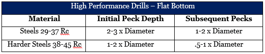
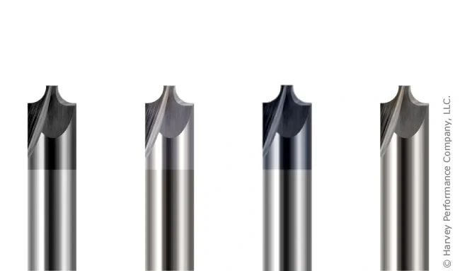
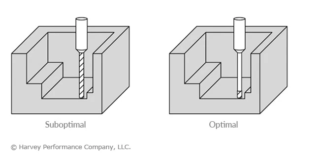
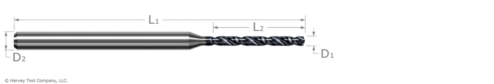
Miniature High Performance Drills – Flat Bottom
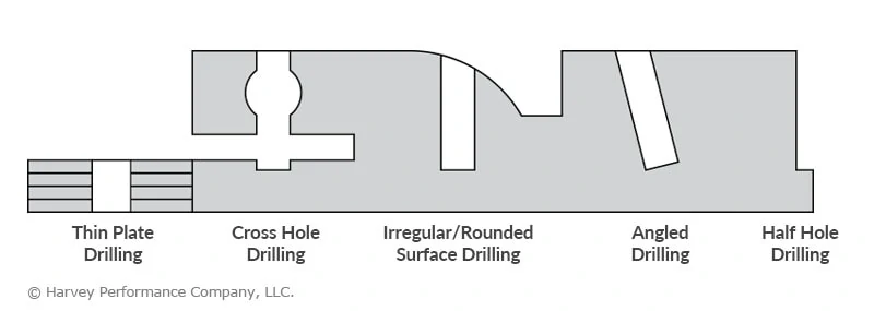
Choose Miniature High Performance Flat Bottom Drills when drilling on inclined and rounded surfaces, or when aiming to leave a flat bottom on your hole. Also, when drilling intersecting holes, half holes, shoulders, or thin plates, its flat bottom tool geometry helps to promote accuracy and a clean finish.
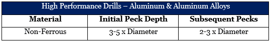
Miniature High Performance Drills – Aluminum Alloys
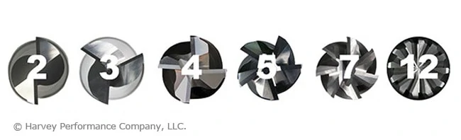
The line of High Performance Drills for Aluminum Alloys feature TiB2 coating, which has an extremely low affinity to Aluminum and thus will fend off built-up edge. Its special 3 flute design allows for maximum chip flow, hole accuracy, finish, and elevated speeds and feeds parameters in this easy-to-machine material.
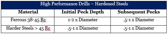
Miniature High Performance Drills – Hardened Steels
Miniature High Performance Drills – Hardened Steels features a specialized flute shape for improved chip evacuation and maximum rigidity. Additionally, each drill is coated in AlTiN Nano coating for hardness, and heat resistance in materials 48 Rc to 68 Rc.
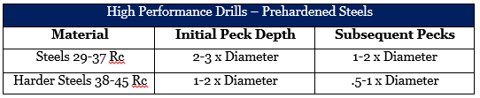
Miniature High Performance Drills – Prehardened Steels
As temperatures rise during machining, the AlTiN coating featured on Harvey Tool’s Miniature High Performance Drills – Prehardened Steels creates an aluminum oxide layer which helps to reduce thermal conductivity of the tool and helps to promote heat transfer to the chip, as well as improve lubricity and heat resistance in ferrous materials.

Post-Drilling Considerations
Miniature Reamers
For many operations, drilling the actual hole is only the beginning of the job. Some parts may require an ultra-tight tolerance, for which a Miniature Reamer (tolerances of +.0000″/-.0002″ for uncoated and +.0002″/-.0000″ for AlTiN Coated) can be used to bring a hole to size. 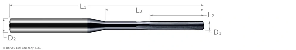
Tech Tip: In order to maintain appropriate stock removal amounts based on the reamer size, a hole should be pre-drilled at a diameter that is 90-94 percent of the finished reamed hole diameter.
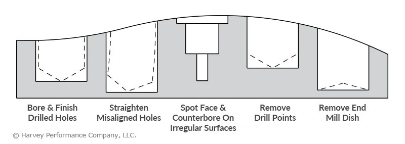
Flat Bottom Counterbores
Other operations may require a hole with a flat bottom to allow for a superior connection with another part. Flat Bottom Counterbores leave a flat profile and straighten misaligned holes. For more information on why to use a Flat Bottom Counterbore, read 10 Reasons to Use Flat Bottom Tools.

Key Next Steps
Now that you’re familiar with miniature drills and complementary holemaking tooling, you must now learn key ways to go about the job. Understanding the importance of pecking cycles, and using the correct approach, is vital for both the life of your tool and the end result on your part. Read this post’s complement “Choosing the Right Pecking Cycle Approach,” for more information on the approach that’s best for your application.