Whether your tool is a 1” diameter powerhouse rougher or a .032” precision end mill, slotting is one of the hardest operations on the tool. During slotting operations, a lot of force and pressure is placed on the entire cutting edge of the tool. This results in slower speeds and feeds and increased tool wear, making it one of the nastier processes even for the best cutting tools.
With miniature tooling (for the purposes of this blog, under 1/8” diameter) the game changes. The way we approach miniature tooling is completely different as it relates to slotting. In these instances, it is vitally important to select the correct tool for these operations. A few of the suggestions may surprise you if you are used to working with larger tooling, but rest assured, these are tried and tested recommendations which will dramatically increase your success rate in miniature slotting applications.
Use as Many Flutes as Possible
When running traditional slotting toolpaths, the biggest concern with the cutting tool is getting the best chip evacuation by using the proper flute count. Traditionally speaking, you want to use the fewest amount of flutes possible. In Aluminum/Non-Ferrous jobs, this is typically no more than 2/3 flutes, and in Steel/Ferrous applications, 4 flutes is recommended. The lower flute count leaves room for the chips to evacuate so you are not re-cutting chips and clogging the flutes on your tool in deep slots.
When slotting with miniature tools, the biggest concerns are with tool rigidity, deflection, and core strength. With micro-slotting we are not “slotting”, but rather we are “making a slot”. In traditional slotting, we may drive a ½” tool down 2xD into the part to make a full slot, and the tool can handle it! But this technique simply isn’t possible with a smaller tool.
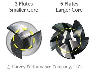
For example, let’s take a .015” end mill. If we are making a slot that is .015” deep with that tool, we are likely going to take a .001” to .002” axial depth per pass. In this case, chips are no longer your problem since it is not a traditional slotting toolpath. Rigidity and core strength are now key, which means we need to add as many flutes as possible! Even in materials like Aluminum, 4 or 5 flutes will be a much better option at smaller diameters than traditional 2/3 flute tools. By choosing a tool with a higher flute count, some end users have seen their tool life increase upwards of 50 to 100 times over tools with lower flute counts and less rigidity and strength.
Use the Strongest Corner Possible When Slotting
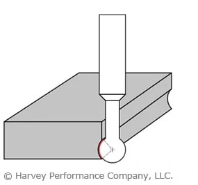
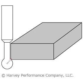
Outside of making sure you have a strong core on your miniature tools while making a slot, you also need to take a hard look at your corner strength. Putting a corner radius on your tooling is a great step and does improve the corner strength of the tool considerably over a square profile tool. However, if we want the strongest tip geometry, using a ball nose end mill should also be considered.
A ball nose end mill will give you the strongest possible tip of the three most common profiles. The end geometry on the ball nose can almost work as a high feed end mill, allowing for faster feed rates on the light axial passes that are required for micro-slotting. The lead angle on the ball nose also allows for axial chip thinning, which will give you better tool life and allow you to decrease your cycle times.
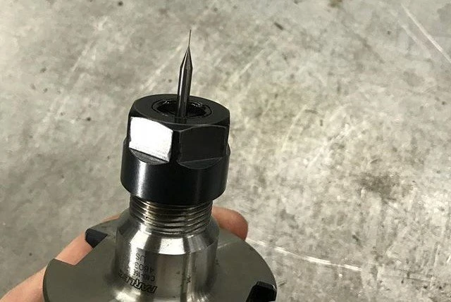
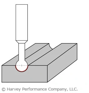
A .078″ ball nose end mill was used for this miniature slotting operation
Finding the Right Tool for Miniature Slotting Operations
Precision and accuracy are paramount when it comes to miniature tooling, regardless of whether you are slotting, roughing, or even simply looking to make a hole in a part. With the guidelines above, it is also important to have a variety of tooling options available to cater to your specific slotting needs. Harvey Tool offers 5 flute end mills down to .015” in diameter, which are a great option for a stronger tool with a high flute count for slotting operations.
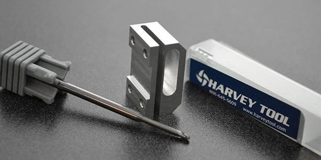
Harvey Tool offers many miniature end mill options, like the .010″ long reach end mill above.
If you are looking to upgrade your corner strength, Harvey Tool also offers a wide selection of miniature end mills in corner radius and ball nose profiles, with dozens of reach, length of cut, and flute count options. Speeds and feeds information for all of these tools is also available, making your programming of these difficult toolpaths just a little bit easier.
Achieving Slotting Success: Summary
To wrap things up, there are three major items to focus on when it comes to miniature slotting: flute count, corner strength, and the depth of your axial passes.
It is vital to ensure you are using a corner radius or ball nose tool and putting as many flutes as you can on your tool when possible. This keeps the tool rigid and avoids deflection while providing superior core strength.
For your axial passes, take light passes with multiple stepdowns. Working your tool almost as a high feed end mill will make for a successful slotting operation, even at the most minuscule diameters.
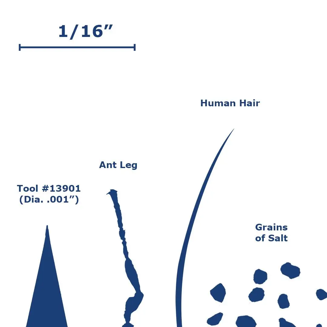
The machining industry generally considers micromachining and miniature end mills to be any end mill with a diameter under 1/8 of an inch. This is also often the point where tolerances must be held to a tighter window. Because the diameter of a tool is directly related to the strength of a tool, miniature end mills are considerably weaker than their larger counterparts, and therefore, lack of strength must be accounted for when micromachining. If you are using these tools in a repetitive application, then optimization of this process is key.
Size Comparison for Harvey Tool’s #13901 Square Miniature End Mill
Key Cutting Differences Between Conventional and Miniature End Mills
Runout
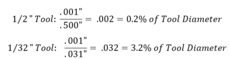
Runout during an operation has a much greater effect on miniature tools, as even a very small amount can have a large impact on the tool engagement and cutting forces. Runout causes the cutting forces to increase due to the uneven engagement of the flutes, prompting some flutes to wear faster than others in conventional tools, and breakage in miniature tools. Tool vibration also impacts the tool life, as the intermittent impacts can cause the tool to chip or, in the case of miniature tools, break. It is extremely important to check the runout of a setup before starting an operation. The example below demonstrates how much of a difference .001” of runout is between a .500” diameter tool and a .031” diameter tool.
The runout of an operation should not exceed 2% of the tool diameter. Excess runout will lead to a poor surface finish.
Chip Thickness
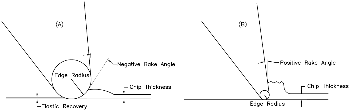
The ratio between the chip thickness and the edge radius (the edge prep) is much smaller for miniature tools. This phenomena is sometimes called “the size effect” and often leads to an error in the prediction of cutting forces. When the chip thickness-to-edge radius ratio is smaller, the cutter will be more or less ploughing the material rather than shearing it. This ploughing effect is essentially due to the negative rake angle created by the edge radius when cutting a chip with a small thickness.
If this thickness is less than a certain value (this value depends of the tool being used), the material will squeeze underneath the tool. Once the tool passes and there is no chip formation, part of the plowed material recovers elastically. This elastic recovery causes there to be higher cutting forces and friction due to the increased contact area between the tool and the workpiece. These two factors ultimately lead to a greater amount of tool wear and surface roughness.
Figure 1: (A) Miniature tool operation where the edge radius is greater than the chip thickness (B) Conventional operation where the edge radius is small than the chip thickness
Tool Deflection in Conventional vs. Micromachining Applications
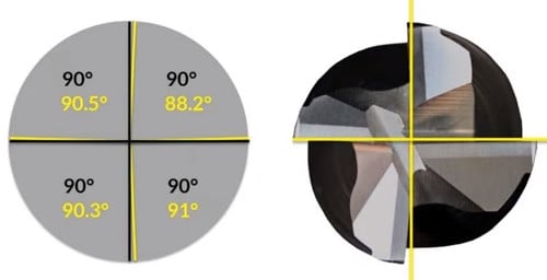
Tool deflection has a much greater impact on the formation of chips and accuracy of the operation in micromachining operations, when compared to conventional operations. Cutting forces concentrated on the side of the tool cause it to bend in the direction opposite the feed. The magnitude of this deflection depends upon the rigidity of the tool and its distance extended from the spindle. Small diameter tools are inherently less stiff compared to larger diameter tools because they have much less material holding them in place during the operation. In theory, doubling the length sticking out of the holder will result in 8 times more deflection. Doubling the diameter of an end mill it will result in 16 times less deflection. If a miniature cutting tool breaks on the first pass, it is most likely due to the deflection force overcoming the strength of the carbide. Here are some ways you can minimize tool deflection.
Workpiece Homogeny
Workpiece homogeny becomes a questionable factor with decreasing tool diameter. This means that a material may not have uniform properties at an exceptionally small scale due to a number of factors, such as container surfaces, insoluble impurities, grain boundaries, and dislocations. This assumption is generally saved for tools that have a cutter diameter below .020”, as the cutting system needs to be extremely small in order for the homogeny of the microstructure of the material to be called into question.
Surface Finish
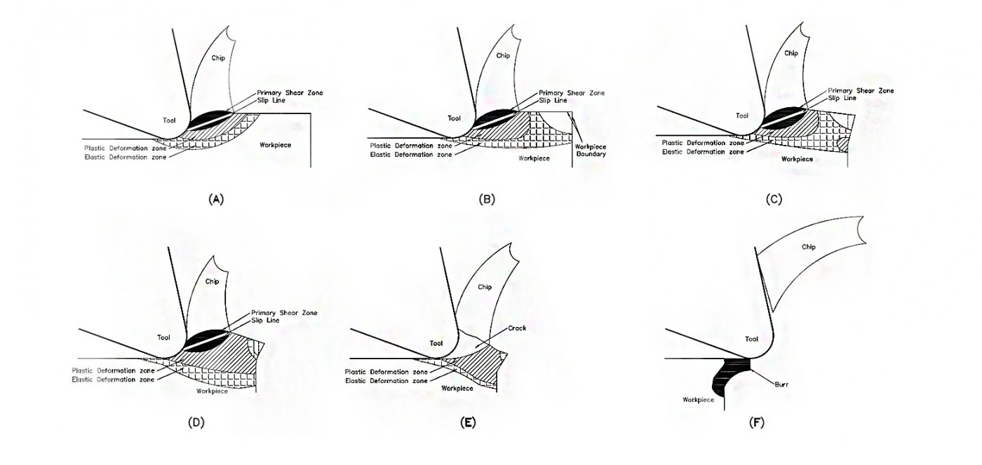
Micromachining may result in an increased amount of burrs and surface roughness when compared to conventional machining. In milling, burring increases as feed increases, and decreases as speed increases. During a machining operation, chips are created by the compression and shearing of the workpiece material along the primary shear zone. This shear zone can be seen in Figure 2 below. As stated before, the chip thickness-to-edge radius ratio is much higher in miniature applications. Therefore, plastic and elastic deformation zones are created during cutting and are located adjacent to the primary shear zone (Figure 2a). Consequently, when the cutting edge is close to the border of the workpiece, the elastic zone also reaches this border (Figure 2b). Plastic deformation spreads into this area as the cutting edge advances, and more plastic deformation forms at the border due to the connecting elastic deformation zones (Figure 2c). A permanent burr begins to form when the plastic deformation zones connect (Figure 2d) and are expanded once a chip cracks along the slip line (Figure 2e). When the chips finally break off from the edge of the workpiece, a burr is left behind (Figure 2f).
Figure 2: Burr formation mechanism using a miniature end mill
Tool Path Best Practices for Miniature End Mills
Because of the fragility of miniature tools, the tool path must be programmed in such a way as to avoid a sudden amount of cutting force, as well as permit the distribution of cutting forces along multiple axes. For these reasons, the following practices should be considered when writing a program for a miniature tool path:
Ramping Into a Part
Circular ramping is the best practice for moving down axially into a part, as it evenly distributes cutting forces along the x, y, and z planes. If you have to move into a part radially at a certain depth of cut, consider an arching tool path as this gradually loads cutting forces onto the tool instead of all at once.
Micromachining in Circular Paths
You should not use the same speeds and feed for a circular path as you would for a linear path. This is because of an effect called compounded angular velocity. Each tooth on a cutting tool has its own angular velocity when it is active in the spindle. When a circular tool path is used, another angular velocity component is added to the system and, therefore, the teeth on the outer portion of tool path are traveling at a substantially different speed than expected. The feed of the tool must be adjusted depending on whether it is an internal or external circular operation. To find out how to adjust your feed, check out this article on running in circles.
Do not approach a miniature slot the same way as you would a larger slot. With a miniature slot, you want as many flutes on the tool as possible, as this increases the rigidity of the tool through a larger core. This decreases the possibility of the tool breaking due to deflection. Because there is less room for chips to evacuate with a higher number of flutes, the axial engagement must be decreased. With larger diameter tools you may be stepping down 50% – 100% of the tool diameter. But when using miniature end mills with a higher flute count, only step down between 5% – 15%, depending on the size of the diameter and risk of deflection. The feed rate should be increased to compensate for the decreased axial engagement. The feed can be increased even high when using a ball nose end mill as chip thinning occurs at these light depths of cut and begins to act like a high feed mill.
Slowing Down Your Feed Around Corners
Corners of a part create an additional amount of cutting forces as more of the tool becomes engaged with the part. For this reason it is beneficial to slow down your feed when machining around corners to gradually introduce the tool to these forces.
This is somewhat of a tricky question to answer when it comes to micromachining. Climb milling should be utilized whenever a quality surface finish is called for on the part print. This type of tool path ultimately leads to more predictable/lower cutting forces and therefore higher quality surface finish. In climb milling, the cutter engages the maximum chip thickness at the beginning of the cut, giving it a tendency to push away from the workpiece. This can potentially cause chatter issues if the setup does not have enough rigidity. In conventional milling, as the cutter rotates back into the cut it pulls itself into the material and increases cutting forces. Conventional milling should be utilized for parts with long thin walls as well as delicate operations.
Combined Roughing and Finishing Operations
These operations should be considered when micromachining tall thin walled parts as in some cases there is not sufficient support for the part for a finishing pass.
Helpful Tips for Achieving Successful Micromachining Operations With Miniature End Mills
Try to minimize runout and deflection as much as possible when micromachining with miniature end mills. This can be achieved by using a shrink-fit or press-fit tool holder. Maximize the amount of shank contact with the collet while minimizing the amount of stick-out during an operation. Double check your print and make sure that you have the largest possible end mill because bigger tools mean less deflection.
Choose an appropriate depth of cut so that the chip thickness to edge radius ratio is not too small as this will cause a ploughing effect.
If possible, test the hardness of the workpiece before machining to confirm the mechanical properties of the material advertised by the vender. This gives the operator an idea of the quality of the material.
Use a coated tool if possible when working in ferrous materials due to the excess amount of heat that is generated when machining these types of metals. Tool coatings can increase tool life between 30%-200% and allows for higher speeds, which is key in micro-machining.
Consider using a support material to control the advent of burrs during a micromachining application. The support material is deposited on the workpiece surface to provide auxiliary support force as well as increase the stiffness of the original edge of the workpiece. During the operation, the support material burrs and is plastically deformed rather than the workpiece.
Use flood coolant to lower cutting forces and a greater surface finish.
Scrutinize the tool path that is to be applied as a few adjustments can go a long way in extending the life of a miniature tool.
Double-check tool geometry to make sure it is appropriate for the material you are machining. When available, use variable pitch and variable helix tools as this will reduce harmonics at the exceptionally high RPMs that miniature tools are typically run at.
Figure 3: Variable pitch tool (yellow) vs. a non-variable pitch tool (black)
https://www.harveyperformance.com/wp-content/uploads/2020/07/Feature-Image-Machining-with-Miniature-End-Mills-IMG-1.jpg5251400Robert Keeverhttp://www.harveyperformance.com/wp-content/uploads/2018/08/Logo_HarveyPerformanceCompany-4.pngRobert Keever2020-07-01 10:43:432024-02-08 15:36:10How to Optimize Results While Machining With Miniature End Mills
When a machinist needs to cut material significantly deeper than wide, a Slitting Saw is an ideal choice to get the job done. These are unique due to their composition and rigidity, which allows it to hold up in a variety of both straightforward and tricky to machine materials.
What is a Slitting Saw?
A Slitting Saw is a flat (with or without a dish), circular-shaped tool that has a hole in the middle and teeth on the outer diameter. Used in conjunction with an arbor, this tool is intended for machining purposes that require a large amount of material to be removed within a small diameter, such as slotting or cutoff applications.
Other names include (but are not limited to) Slitting Cutters, Slotting Cutters, Jewelers Saws, and Slitting Knives. Both Jewelers Saws and Slitting Knives are particular types of saws. Jewelers Saws have a high tooth count enabling them to cut tiny, precise features, and Slitting Knives have no teeth at all. On Jewelers Saws, the tooth counts are generally much higher than other types of saws in order to make the cuts as accurate as possible.
Key Terminology
Why Use a Slitting Saw?
These saws are designed for cutting into both ferrous and non-ferrous materials, and by utilizing their unique shape and geometries, they can cut thin slot type features on parts more efficiently than any other machining tool. Non-Ferrous slitting saws have fewer teeth, allowing for aggressively deep depths of cut.
Common Applications:
Separating Two Pieces of Material
If an application calls for cutting a piece of material, such as a rod, in half, then a slitting saw will work well to cut the pieces apart while increasing efficiency.
Undercutting Applications
Saws can perform undercutting applications if mounted correctly, which can eliminate the need to remount the workpiece completely.
Slotting into Material
Capable of creating thin slots with a significant depth of cut, Slitting Saws can be just the right tool for the job!
When Not to Use a Slitting Saw
While it may look similar to a stainless steel circular saw blade from a hardware store, this tool should neverbe used with construction tools such as a table or circular saw. Brittle saw blades will shatter when used on manual machines, and can cause injury when not used on the proper set up.
In Conclusion
Slitting Saws can be beneficial to a wide variety of machining processes, and it is vital to understand their geometries and purpose before attempting to utilize them in the shop. They are a great tool to have in the shop and can assist with getting jobs done as quickly and efficiently as possible.
https://www.harveyperformance.com/wp-content/uploads/2019/09/Feature-Image-Slitting-Saws-IMG.jpg5251400Harvey Performance Companyhttp://www.harveyperformance.com/wp-content/uploads/2018/08/Logo_HarveyPerformanceCompany-4.pngHarvey Performance Company2019-09-10 09:30:532021-11-19 08:37:59The Geometries and Purposes of a Slitting Saw
Machinists have a number of variables to consider when setting up devices for a machining operation. When it comes to cnc workholding, there are some major differences between holding a loosely toleranced duplicate part with a 10-minute cycle time and holding a tightly toleranced specialized part with a 10-hour cycle time. Determining which method works best for your machining job is essential to maintaining an efficient operation.
CNC Workholding Devices
Ideal workholding devices have easily repeatable setups. For this reason, some machines have standard workholding devices. Vises are generally used with milling machines while chucks or collets are used when running a lathe machine. Sometimes, a part may need a customized cnc workholding setup in order to secure the piece properly during machining. Fixtures and jigs are examples of customized devices.
Fixtures and Jigs
A jig is a work holding device that holds, supports and locates a workpiece and guides the cutting tool into a specific operation (usually through the use of one or more bushings). A fixture is essentially the same type of device, but the main difference is that it does not guide the cutting tool into a specified operation. Fixtures are typically used in milling operations while jigs are generally used in drilling, reaming, tapping and boring. Jigs and fixtures are more precise relative to standard cnc workholding devices, which leads to tighter tolerances. They can also be indexable, allowing them to control the cutting tool movement as well as workpiece movement. Both jigs and fixtures are made up of the same basic components: fixture bodies, locators, supports, and clamps.
The 4 Fixture Bodies
There are 4 basic types of fixture bodies: faceplates, baseplates, angle plates, and tombstones.
Faceplates: Typically used in lathe operations, where components are secured to the faceplate and then mounted onto the spindle.
Baseplates: Common in milling and drilling operations and are mounted to the worktable.
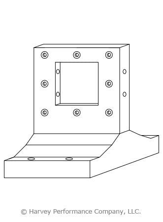
Angle plates: Two plates perpendicular to each other but some are adjustable or customized to change the angle of the workpiece.
Tombstones: Large vertically oriented rectangular fixtures that orients a workpiece perpendicular to the worktable. Tombstones also have two sides to accommodate multiple parts.
Locators
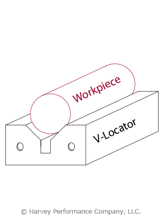
Locators are characterized by four criteria: assembled, integral, fixed, and adjustable. Assembled locators, can be attached and removed from the fixture, which is contrary to integral locators that are built into the fixture. Fixed locators allow for no moving components, while adjustable locators permit movement through the use of threads and/or springs, and can adjust to a workpiece’s size. These can be combined to provide the appropriate rigidity-assembly convenience ratio. For example, a V-locator fixture is the combination of assembled and fixed locators. It can be secured to a fixture but has no moving components.
Supports
Supports do exactly what their name suggests, they support the workpiece during the machining process to avoid workpiece deformation. These components can double as locators and also come fixed, adjustable and integral, or assembled. Generally, supports are placed under the workpiece during manufacturing but this also depends on the geometry of the workpiece, the machine being operated and where the cutting tool will make contact. Supports can come in different shapes and sizes. For example, rest buttons are smaller support components used in series either from underneath the workpiece or from the sides. Concurrently, parallel supports are placed on either side of the part to provide general support.
Clamps
Clamps are devices used for strengthening or holding things together, and come in different shapes, sizes and strengths. Vises and chucks have movable jaws and are considered standard clamps. One atypical example is the toggle clamp, which has a pivot pin that acts as a fulcrum for a lever system. One of the more convenient types is a power clamping system. There are two type of power clamping methods: hydraulic and pneumatic.
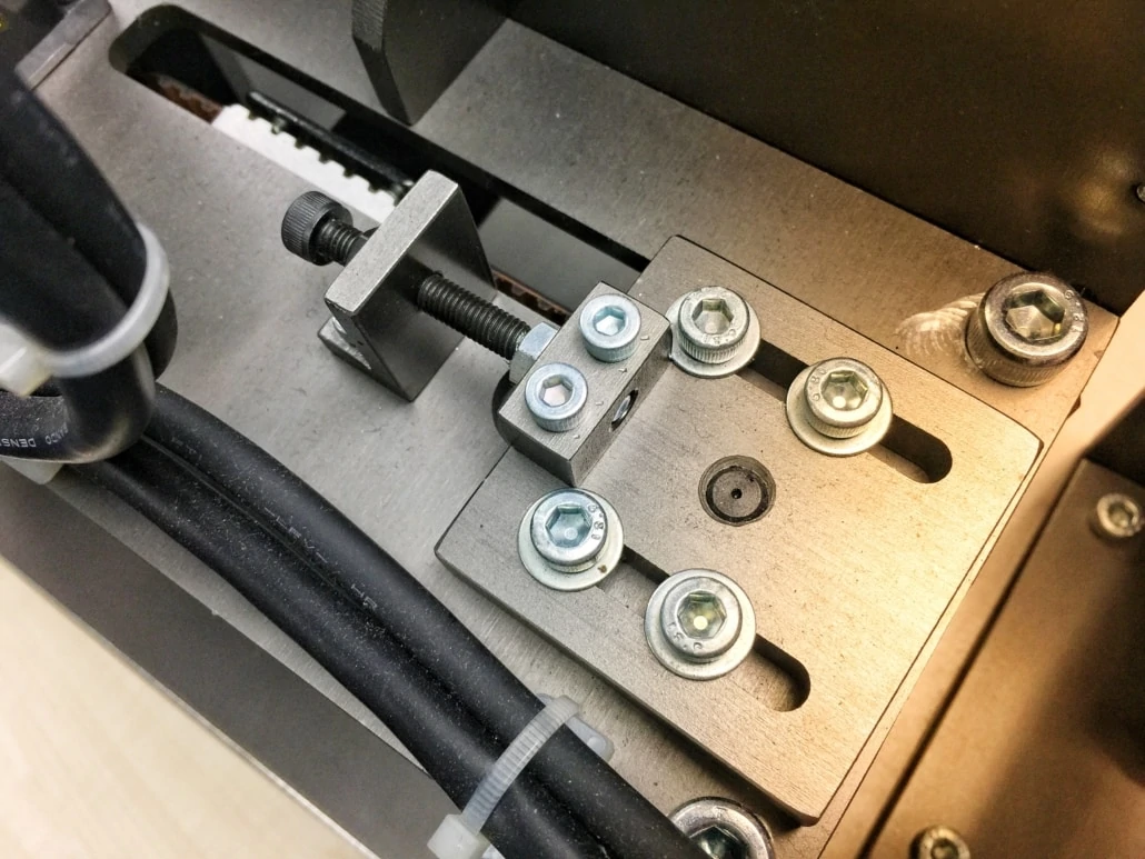
Example of a standard fixture setup.
Hydraulic Workholding Systems
Hydraulic Systems create a gripping force by attaining power from compressing a liquid. This type of power clamp is generally used with larger workpieces as it usually takes up less space relative to pneumatic clamps.
Pneumatic clamps
Pneumatic clamps attain their gripping force from the power created by a compressed gas (usually air). These systems are generally bulkier and are used for smaller workpieces that require less room on the worktable. Power clamping offers a few advantages over conventional clamping. First, these systems can be activated and deactivated quickly to save on changeover time. Second, they place uniform pressure on the part, which help prevent errors and deformation. A significant disadvantage they pose is the cost of a system but this can be quickly offset by production time saved.
Key Guidelines to Follow
Lastly, there are a few guidelines to follow when choosing the appropriate CNC workholding fixture or jig setup.
Ensure Proper Tolerancing
The tolerances of the workholding device being used should be 20%-50% tighter than those of the workpiece.
Utilize Acceptable Locating & Supporting Pieces
Locating and supporting pieces should be made of a hardened material to prevent wear and allow for several uses without the workpieces they support falling out of tolerance. Supports and locators should also be standardized so that they can be easily replaced.
Place Workholding Clamps in Correct Locations
Clamps should be placed above the locations of supports to allow the force of the clamp to pass into the support without deforming the workpiece. Clamps, locators and supports should also be placed to distribute cutting forces as evenly as possible throughout the part. The setup should allow for easy clamping and not require much change over time
Maximize Machining Flexibility
The design of the fixture or jigs should maximize the amount of operations that can be performed in one orientation. During the machining operation, the setup should be rigid and stable.
Bottom Line
Workholding can be accomplished in a number of different ways and accomplish the same task of successfully gripping a part during a machining operation with the end result being in tolerance. The quality of this workholding may differ greatly as some setups will be more efficient than others. For example, there is no reason to create an elaborate jig for creating a small slot down the center of a rectangular brick of aluminum; a vise grip would work just fine. Maximizing the efficiency and effectiveness of an operators’ cnc workholding setup will boost productivity by saving on changeover, time as well as cost of scrapped, out of tolerance parts.
Stainless steel can be as common as Aluminum in many shops, especially when manufacturing parts for the aerospace and automotive industries. It is a fairly versatile material with many different alloys and grades which can accommodate a wide variety of applications. However, milling steel can also be immensely difficult. Stainless steels are notorious end mill assassins, so dialing in your speeds and feeds and selecting the proper tool is essential for machining success.
Material Properties
Stainless steels are high-alloy steels with superior corrosion resistance to carbon and low-alloy steels. This is largely due to their high chromium content, with most grades of stainless steel alloys containing at least 10% of the element.
Stainless steel can be broken out into one of five categories: Austenitic, Ferritic, Martensitic, Precipitation Hardened (PH), and Duplex. In each category, there is one basic, general purpose alloy. From there, small changes in composition are made to the base in order to create specific properties for various applications.
For reference, here are the properties of each of these groupings, as well as a few examples of the popular grades and their common uses.
Category
Properties
Popular Grades
Common Uses
Austenitic
Non-magnetic, outstanding corrosion and heat resistance.
304, 316
Food processing equipment, gutters, bolts, nuts, and other fasteners.
Ferritic
Magnetic, lower corrosion and heat resistance than Austenitic.
430, 446
Automotive parts and kitchen appliances.
Martensitic
Magnetic, moderate corrosion resistance – not for severe corrosion.
416, 420, 440
Knives, firearms, surgical instruments, and hand tools.
Precipitation Hardened (PH)
Strongest grade, heat treatable, severe corrosion resistance.
17-4 PH, 15-5 PH
Aerospace components.
Duplex
Stronger mixture of both Austenitic and Ferritic.
244, 2304, 2507
Water treatment plants, pressure vessels.
Tool Selection
Choosing the correct tooling for your application is crucial when machining stainless steel. Roughing, finishing, slotting, and high efficiency milling toolpaths can all be optimized for stainless steel by choosing the correct style of end mill.
Traditional Roughing
For traditional roughing, a 4 or 5 flute end mill is recommended. 5 flute end mills will allow for higher feed rates than their 4 flute counterparts, but either style would work well for roughing applications. Below is an excellent example of traditional roughing in 17-4 Stainless Steel.
Slotting
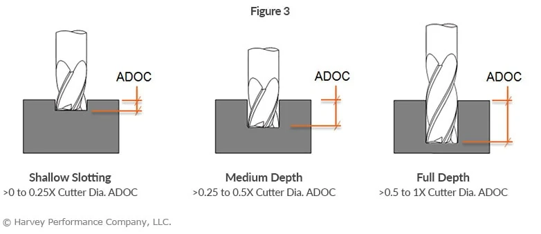
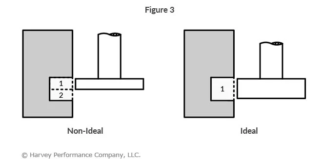
The axial engagement of a tool in a slotting operation should be suitable for the specific tool employed, as depicted in Figure 3. Employing an unsuitable method may result in tool deflection, potential damage, and compromised part quality. Chip evacuation is going to be key for slotting in stainless steel. For this reason, 4 flute tools are the best choice because the lower flute count allows for more efficient chip evacuation. Tools with chipbreaker geometry also make for effective slotting in stainless steel, as the smaller chips are easier to evacuate from the cut.
Finishing
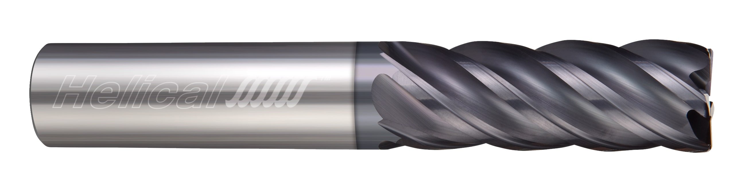
When finishing stainless steel parts, a high flute count and/or high helix is required for the best results. Finishing end mills for stainless steel will have a helix angle over 40 degrees, and a flute count of 5 or more. For more aggressive finishing toolpaths, flute count can range from 7 flutes to as high as 14. Below is a great example of a finishing run in 17-4 Stainless Steel.
High Efficiency Milling
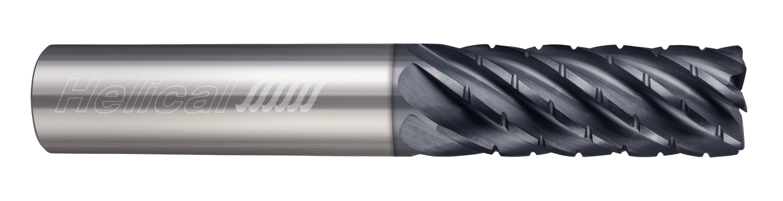
High Efficiency Milling (HEM) can be a very effective machining technique in stainless steels if the correct tools are selected. Chipbreaker roughers would make an excellent choice, in either 5 or 7 flute styles, while standard 5-7 flute, variable pitch end mills can also perform well in HEM toolpaths.
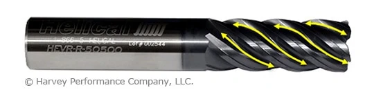
HEV-5
Helical Solutions offers the HEV-5 end mill, which is an extremely versatile tool for a variety of applications. The HEV-5 excels in finishing and HEM toolpaths, and also performs well above average in slotting and traditional roughing. Available in square, corner radius, and long reach styles, this well-rounded tool is an excellent choice to kickstart your tool crib and optimize it for stainless steel machining.
Running Parameters
While tool selection is a critical step to more effective machining, dialing in the proper running parameters is equally important. There are many factors that go into determining the running parameters for stainless steel machining, but there are some general guidelines to follow as a starting point.
Generally speaking, when machining stainless steels a SFM of between 100-350 is recommended, with a chip load ranging between .0005” for a 1/8” end mill up to .006” for a 1” end mill. A full breakdown of these general guidelines is available here.
Machining Advisor Pro
Machining Advisor Pro is a cutting edge resource designed to precisely calculate running parameters for high performance Helical Solutions end mills in materials like stainless steel, aluminum, and much more. Simply input your tool, your exact material grade, and machine setup and Machining Advisor Pro will generate fully customizable running parameters. This free resource allows you to push your tools harder, faster, and smarter to truly dominate the competition.
Stainless steel machining doesn’t have to be hard. By identifying the proper material grade for each part, selecting the perfect cutting tool, and optimizing running parameters, headaches from milling steel can become a thing of the past.
If there is one thing that all machinists and shop managers can agree on, it’s that time is money. CNC tooling and material costs, employee wages, and keeping the lights on all add up, but most would agree that saving time is one of the best ways to make a shop more efficient.
Tool changes mid-job quickly add up when it comes to cycle times (not to mention tool costs), so using a tool capable of multiple operations whenever possible is an excellent first step. The following multi-functional tools are designed to save time and money at the spindle.
Drill/End Mills
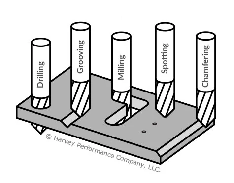
One look at Drill/End Mills or “Drill Mills” and it’s obvious that these multi-functional tools are capable of more than a standard end mill. Two of the intended operations are right in the name (drilling and milling). Besides the obvious, though, drill mills are intended for grooving, spotting, and chamfering, bringing the total to five separate operations.
Considering the amount of tools normally required to perform all of these common operations, keeping a few drill mills in your tool crib ensures you’re always ready to tackle them, not to mention the potential extra spots in your tool magazine.
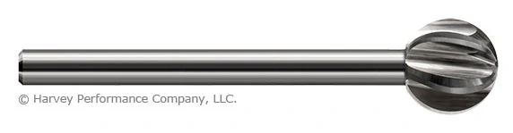
Undercutting End Mills
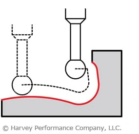
Undercutting End Mills, also known as lollipop cutters or spherical ball end mills are surprisingly “well-rounded” tools. Besides milling an undercut feature on a part, which is typically very difficult with a standard end mill, these tools are capable of a few other operations.
Using an undercutting end mill to deburr in your machine is an excellent way to save time and effort. Some slotting and contouring operations, especially when 5-axis milling, are made far easier with an undercutting end mill, and in some situations, clearance challenges make them necessary.
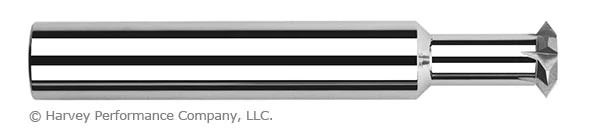
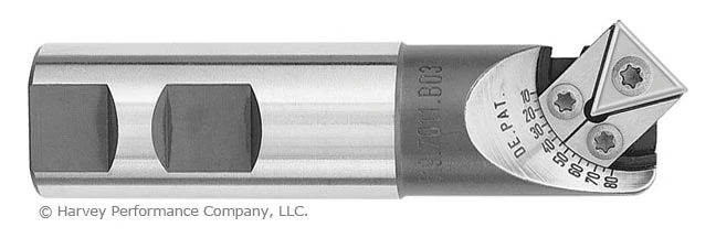
Double Angle Shank Cutters
Often referred to the “Swiss Army Knife of Machining” due to their versatility, Double Angle Shank Cutters are 6-in1 multi-functional tools worth keeping on hand in any machine shop. Since these tools cut on all sides of their head, they are useful in a variety of situations.
With the ability to thread mill and countersink, Double Angle Shank cutters are perfect for holemaking operations. On top of that, their clearance advantage over standard end mills makes them extremely well suited to a variety of finishing operations in difficult to reach places.
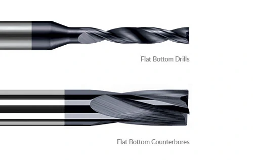
Flat Bottom Tools
Flat Bottom Drills and Flat Bottom Counterbores are better suited to holemaking, but they are capable of a large variety of operations. They belong in a category together since their flat bottom geometry is what sets them apart from other cnc tooling in the same category. Flat bottom geometry keeps the tool from walking on irregular or angle surfaces and help to correct, straighten, or flatten features created by non-flat bottom tools.
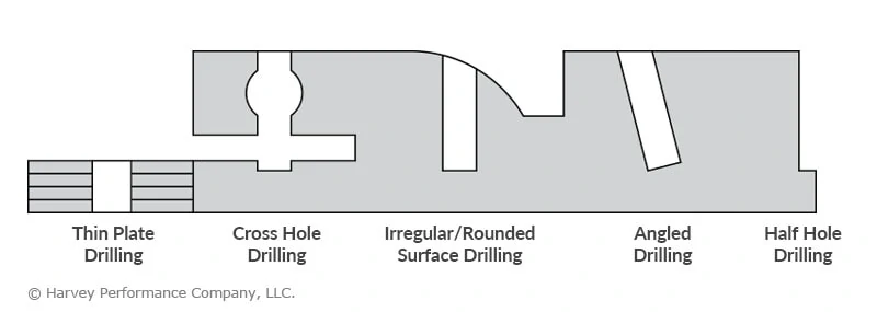
Flat bottom drills are designed for the following operations:
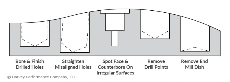
While similar in some aspects, flat bottom counterbores are particularly well-suited for these uses:
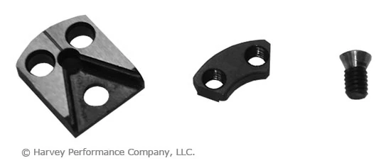
Adjustable Chamfer Cutters
As discussed in a previous post, chamfer mills are capable of more than just chamfering – they are also well-suited for beveling, deburring, spotting, and countersinking. However, these adjustable chamfer cutters aren’t limited to a single angle per side – with a quick adjustment to the carbide insert you can mill any angle from 10° to 80°.
When you account for the replaceable insert and the range of angles, this tool has a very high potential for time and tool cost savings.
Tools that are capable of a variety of operations are useful to just about any machine shop. Keeping your cnc tooling crib stocked with some or all of these multi-functional tools greatly increases your shop’s flexibility and decreases the chances of being unprepared for a job.
https://www.harveyperformance.com/wp-content/uploads/2018/03/Feature-Image-Multi-functional-Tools-IMG.png5271400Harvey Performance Companyhttp://www.harveyperformance.com/wp-content/uploads/2018/08/Logo_HarveyPerformanceCompany-4.pngHarvey Performance Company2018-03-23 09:34:452023-10-12 14:39:42Multi-Functional Tools Every Shop Should Have
Keyseat cutters, also called woodruff cutters, keyway cutters, and T-slot cutters, are a type of cutting tool used frequently by many machinists – some operations are impractical or even impossible without one. If you need one of these tools for your job, it pays to know when and how to pick the right one and how to use it correctly.
Keyseat Cutter Geometry
Selecting and utilizing the right tool is often more complicated than identifying the right diameter and dialing in the speeds and feeds. A keyseat’s strength should be considered carefully, especially in tricky applications and difficult materials.
As with any tool, a longer reach will make this tool more prone to deflection and breakage. A tool with the shortest allowable reach should be used to ensure the strongest tool possible.
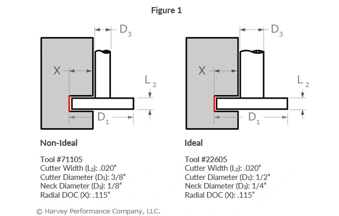
A keyseat cutter’s neck diameter greatly affects its performance. A thinner neck allows for a comparatively larger radial depth of cut (RDOC) and more clearance, but makes for a weaker tool. A thicker neck reduces the cutter’s RDOC, but greatly strengthens the tool overall. When clearances allow, a keyseat cutter with a thicker neck and larger cutter diameter should be chosen over one with a thinner neck and smaller cutter diameter (Figure 1).
Cutter width has an effect on tool strength as well. The greater a keyseat cutter’s cutter width, the more prone to deflection and breakage it is. This is due to the increased forces on the tool – a greater cutter width equates to an increased length of engagement. You should be particularly careful to use the strongest tool possible and a light RDOC when machining with a keyseat cutter with a thick cutter width.
Harvey Tool Keyseat Geometries
Radial Depth of Cut
Understanding a keyseat cutter’s radial depth of cut is critical to choosing the correct tool, but understanding how it affects your tool path is necessary for optimal results. While it may be tempting to make a cut using a keyseat cutter’s maximum RDOC, this will result in increased stress on the tool, a worse finish, and potential catastrophic tool failure. It is almost always better to use a lighter depth of cut and make multiple passes (Figure 2).
When in doubt about what RDOC is correct for your tool and application, consider consulting the tool manufacturer’s speeds and feeds. Harvey Tool’s keyseat cutter speeds and feeds take into account your tool dimensions, workpiece material, operation, and more.
Desired Slot Size
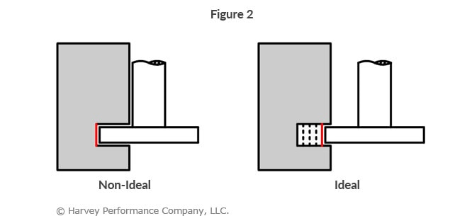
Some machinists use keyseat cutters to machine slots greater than their cutter width. This is done with multiple operations so that, for example, a keyseat cutter with a 1/4” cutter width can create a slot that is 3/8” wide. While this is possible and may save on up-front tooling costs, the results are not optimal. Ideally, a keyseat cutter should be used to machine a slot equal to its cutter width as it will result in a faster operation, fewer witness marks, and a better finish (Figure 3).
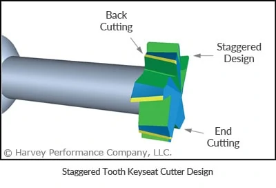
Staggered Tooth Geometry of a Keyseat Cutter
When more versatility is required from a keyseat cutter, staggered tooth versions should be considered. The front and back reliefs allow the tools to cut not only on the OD, but also on the front and back of the head. When circumstances do not allow for the use of a cutter width equal to the final slot dimensions as stated above, a staggered tooth tool can move axially in the slot to expand its width.
Machining difficult or gummy materials can be tricky, and using a staggered tooth keyseat cutter can help greatly with tool performance. The shear flutes reduce the force needed to cut, as well as leave a superior surface finish by reducing harmonics and chatter.
Having trouble finding the perfect keyseat for your job? Harvey Tool offers over 2,100 keyseat cutter options, with cutter diameters from 1/16” to 1-1/2” and cutter widths from .010” to ½”.
NOTE: This article covers speeds and feed rates for milling tools, as opposed to turning tools.
Before using a cutting tool, it is necessary to understand tool cutting speeds and feed rates, more often referred to as “speeds and feeds.” Speeds and feeds are the cutting variables used in every milling operation and vary for each tool based on cutter diameter, operation, material, etc. Understanding the right speeds and feeds for your tool and operation before you start machining is critical. These are to be used to set baselines for a particular tool, ensuring proper performance without compromising part finish and tool life.
Understanding SFM Calculations
It is first necessary to define each of these factors. Cutting speed, also referred to as surface speed, is the difference in speed between the tool and the workpiece, expressed in units of distance over time known as SFM (surface feet per minute). For set-ups with stationary workpieces, SFM is the speed at which a tool moves across the part in the cut. The speed difference must be calculated in set ups where the part and tool are both moving in multi-axis machining set-ups.
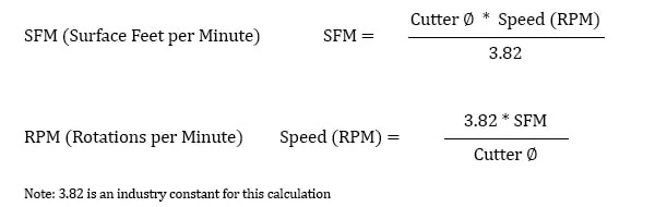
SFM is based on the various properties of the given material. Speed, referred to as Rotations Per Minute (RPM) is based off of the SFM and the cutting tool’s diameter. As SFM is tied to the properties of a material, it does not change based upon the operation being performed and remains constant despite changes in chip load calculation. The SFM calculation utilizes the industry standard of 3.82. Here, the cutter diameter of the chosen tool is multiplied by the speed or RPM. This figure is then divided by 3.82 to generate the SFM or Surface Feet per Minute.
Feed Rate and Chip Load Calculations
While speeds and feeds are common terms used in the programming of the cutter, the ideal running parameters are also influenced by a myriad of other variables. As speeds and feeds must be well-matched to be effective, the speed of the cutter is used in the calculation of the cutter’s feed rate, measured in Inches Per Minute (IPM). The other part of the equation is the chip load, or material being removed per revolution. It is important to note that chip load per tooth and chip load per tool are different:
Chip load per tooth is the appropriate amount of material that one cutting edge of the tool should remove in a single revolution. This is measured in Inches Per Tooth (IPT).
Chip load per tool is the appropriate amount of material removed by all cutting edges on a tool in a single revolution. This is measured in Inches Per Revolution (IPR).
A chip load that is too large can pack up chips in the cutter, causing poor chip evacuation and eventual breakage. A chip load that is too small can cause rubbing, chatter, tool deflection, and a poor overall cutting action. Finding the correct balance will not only allow for the most efficient cut possible, but also ensures the most efficiency in regard to tool wear. When calculating chip load per tool or IPR, the per tooth chip load is aptly multiplied by the number of flutes on the tool itself.
Material Removal Rate
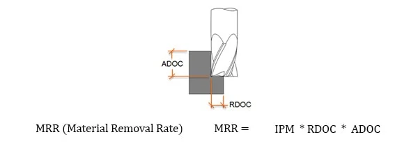
Material Removal Rate (MRR), while not part of the cutting tool’s program, is a helpful way to calculate a tool’s efficiency. MRR takes into account two very important running parameters: Axial Depth of Cut (ADOC), or the distance a tool engages a workpiece along its centerline, and Radial Depth of Cut (RDOC), or the distance a tool is stepping over into a workpiece. The MRR calculation (seen below) relies on the calculated feed rate. The feed rate (IPM) is multiplied by the radial and axial depths of cut to produce the rate of removal.
The tool’s depth of cuts and the rate at which it is cutting can be used to calculate how many cubic inches per minute (in3/min) are being removed from a workpiece. This equation is extremely useful for comparing cutting tools and examining how cycle times can be improved. Decreased cycle times leads to higher productivity within a shop, which is what all machinists aim for during production.
Adjusting depths of cut can decrease time in cut and overall production time, freeing up machines for additional manufacturing. An example of depth of cut adjustment is seen in High Efficiency Milling, where RDOC is decreased and ADOC is increased. In this method, MRR is increased while also reducing tool wear, leading to higher productivity and more parts per tool.
Speeds and Feeds In Practice
While many of the cutting parameters are set by the tool and workpiece material, the depths of cut taken also affect the feed rate of the tool. The depths of cuts are dictated by the operation being performed – this is often broken down into slotting, roughing, and finishing, though there are many other more specific types of operations.
These unique operations utilize much different depths of cut, with industry standardized terms as description. Slotting can be described as utilizing 180° of the diameter of the tool engaged in the cut. Roughing on the other hand will typically disperse both ADOC and RDOC relatively evenly. Finally, finishing operations will use substantially more axial depths of cut in relation to radial, leaving the best finish possible on the workpiece.
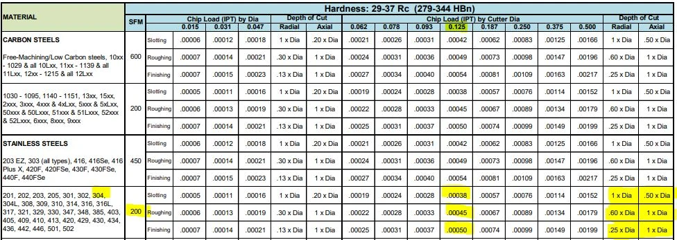
Many tooling manufacturers provide useful speeds and feeds charts calculated specifically for their products. For example, Harvey Tool provides the following chart for a 1/8” diameter end mill, tool #50308. A customer can find the SFM for the material on the left, in this case 304 stainless steel (highlighted in yellow). The chip load (per tooth) can be found by intersecting the tool diameter on the top (blue heading) with the material and operations (based on axial and radial depth of cut), highlighted in the image below.
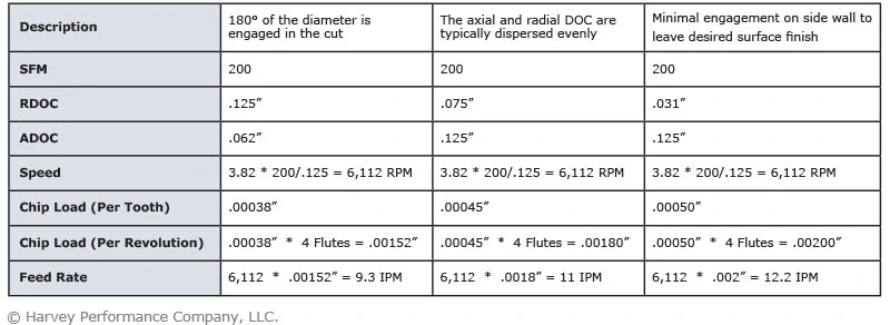
The following table calculates the speeds and feeds for this tool (#50308) and material (304 Stainless) for each operation, based on the chart above:
Each operation recommends a unique chip load per the depths of cut depending on the operation, thus resulting in different feed rates for the desired application. Since the SFM is based on the material, it will always remain constant for each of the three defined operations.
Spindle Speed Cap
As shown above, the cutter speed (RPM) is defined by the SFM (based on material) and the cutter diameter. With miniature tooling and/or certain materials the speed calculation sometimes yields an unrealistic spindle speed. For example, a .047” cutter in 6061 aluminum (SFM 1,000) would return a speed of ~81,000 RPM. Since this speed is only attainable with high speed air spindles, the full SFM of 1,000 may not be achievable. In a case like this, it is recommended that the tool is run at the machine’s max speed (that the machinist is comfortable with) and that the appropriate chip load for the diameter is maintained. This produces optimal parameters based on the machine’s top speed. All machines are unique and provide different max speed, therefore these calculations will vary from machine to machine.
Effective Cutter Diameter
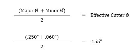
On angled tools the cutter diameter changes along the LOC. For example, Helical tool #07001, a flat-ended chamfer cutter with helical flutes, has a tip diameter of .060” and a major/shank diameter of .250”. In a scenario where it was being used to create a 60° edge break, the actual cutting action would happen somewhere between the tip and major/shank diameters. To compensate, the equation below can be used to find the average diameter along the chamfer.
Using this calculation, the effective cutter diameter is .155”, which would be used for all Speeds and Feeds calculations.
Non-linear Path
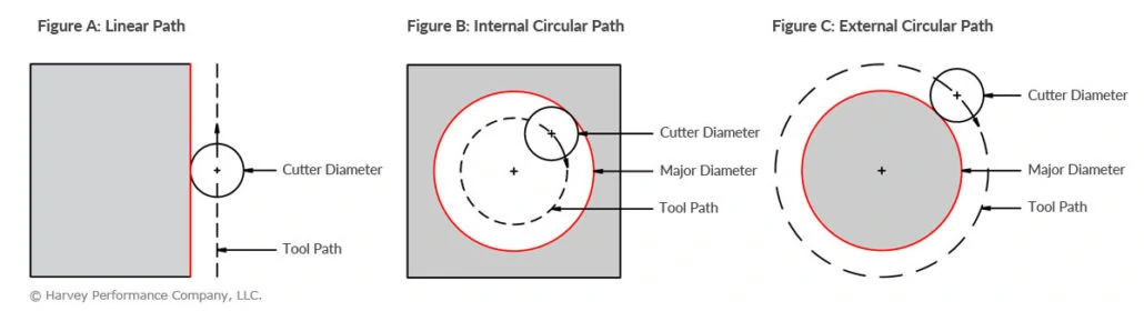
Feed rates assume a linear motion. However, there are cases in which the path takes an arc, such as in a pocket corner or a circular interpolation. Just as increasing the DOC increases the angle of engagement on a tool, so does taking a nonlinear path. For an internal corner, more of the tool is engaged and, for an external corner, less is engaged. The feed rate must be appropriately compensated for the added or lessened engagement on the tool to provide the most effective and desired IPM for the chosen application.
In the below graphic, Figure A is showcasing a linear path on a part, with a standard engagement. Figure’s B and C demonstrate the increase and decrease of engagement in non-linear, circular toolpaths. Utilizing identical feed rates between the three paths would generate three wildly different IPMs despite similar setups.
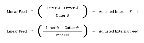
This adjustment is even more important for circular interpolation. Take, for example, a threading application involving a cutter making a circular motion about a pre-drilled hole or boss. For internal adjustment, the feed rate must be lowered to account for the additional engagement. For external adjustment, the feed rate must be increased due to less tool engagement.
An adjustment in internal feed subtracts the differences in cutter diameters from the differences in outer diameters before dividing by the outer dia. difference. On the other hand, adjusting for external feed adds the differences between cutter diameters to the differences in inner diameters before dividing by the inner dia. difference.
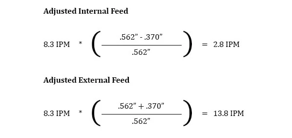
Take this example, in which a Harvey Tool threadmill #70094, with a .370” cutter diameter, is machining a 9/16-18 internal thread in 17-4 stainless steel. The calculated speed is 2,064 RPM and the linear feed is 8.3 IPM. The thread diameter of a 9/16 thread is .562”, which is used for the inner and outer diameter in both adjustments. After plugging these values into the equations below, the adjusted internal feed becomes 2.8 IMP, while the external feed becomes 13.8 IPM.
Conclusion
These calculations are useful guidelines for running a cutting tool optimally in various applications and materials. However, the tool manufacturer’s recommended parameters are the best place to start for initial numbers and to set a baseline for the best tool performance. After that, it is up to the machinist’s eyes, ears, and experience to help determine the best running parameters, which will vary by set-up, tool, machine, and chosen material. No operation is exactly the same, and nothing occurs in a vacuum. Experience and continued learning will always aid machinists in ensuring the most efficient performance possible in the cut.
The following links have the most up to date information on running parameters for Harvey Tool, Helical, Titan USA, and CoreHog CNC products.
https://www.harveyperformance.com/wp-content/uploads/2017/10/Feature-Image-Speeds-Feeds-IMG.jpg5251400Harvey Performance Companyhttp://www.harveyperformance.com/wp-content/uploads/2018/08/Logo_HarveyPerformanceCompany-4.pngHarvey Performance Company2017-10-02 17:00:172023-11-07 15:24:01Speeds and Feeds 101
One of the most important considerations when choosing an end mill is determining which flute count is best for the job at hand. Both material and application play an important role in this critical part of the tool selection process. Understanding the effects of flute count on other tool properties, and how a tool will behave in different situations is an essential consideration in the tool selection process. As end mills have become more and more advanced, certain standards have been created for flute counts in certain materials. While there is obvious overlap due to a myriad of factors, proper flute count is critical for machining success and ensuring you are making the most of your end mill and it’s associated MRR.
Machining Advisor Pro (MAP) Takes Flute Count Into Consideration When Helping You Dial In Running Parameters.
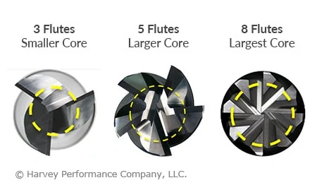
Generally, tools with more flutes have a larger core and smaller flute valleys than tools with fewer flutes. More flutes with a larger core can provide both benefits and restrictions depending on the application. Simply put, a larger core is directly proportional to tool strength; the larger the core, the stronger a tool will be. In turn, a larger core also reduces the flute depth of a tool, restricting the amount of space for chips to exist. This can cause issues with chip packing in applications requiring heavy material removal. However, these considerations only lead us part way when making a decision on which tool to use, and when.
Material Considerations
Traditionally, end mills came in either a 2 flute or 4 flute option. The widely accepted rule of thumb was to use 2 flutes for machining aluminum and non-ferrous materials, and 4 flutes for machining steel and harder alloys. As aluminum and non-ferrous alloys are typically much softer than steels, a tool’s strength is less of a concern, a tool can be fed faster, and larger material removal rates (MRR) is facilitated by the large flute valleys of 2 flute tools.
Consequently, ferrous materials are typically much harder, and require the strength of a larger core. Feed rates are slower, resulting in smaller chips, and allowing for the smaller flute valleys of a larger core tool. This also allows for more flutes to fit on the tool, which in turn increases productivity.
Recently, with more advanced machines and toolpaths, higher flute count tools have become the norm in manufacturing. Non-ferrous tooling has become largely centered on 3 flute tools. This has created a slight advantage over 2 flute tools by increasing productivity while still affording proper chip evacuation. The softness of non-ferrous materials affords a much deeper flute valley. As previously discussed, this allows the tool to be fed much faster than in ferrous materials. Adding an additional flute increases the productivity of the tool, while still affording machinists faster feed rates.
Ferrous tooling has taken a step further and progressed not only to 5 and 6 flutes, but up to 7 flutes and more in some cases. With a wider range of hardness, sometimes at the very top of the Rockwell hardness scale, many more flutes have allowed longer tool life, less tool wear, stronger tools, and less deflection. All of this results in more specialized tools for more specific materials. Material specific tooling combines proper flute counts with coatings that aid in lubricity and heat generation to ensure the most effective end mill possible in the material being machined. The end result is higher MRR and increased productivity across the entire range of ferrous materials that machinists will work with in their shops.
Running Parameters
Just as material considerations will have an impact on the tool you choose, operation type and depth of cut requirements may also have a big impact on the ideal number of flutes for your application. In roughing applications, lower flute counts may be desirable to evacuate large amounts of chips faster with larger flute valleys. That said, there is a balance to find, as modern toolpaths such as High Efficiency Milling (HEM) can achieve extreme MRR with a very small step over, and a higher number of flutes. In a more traditional sense, higher flute counts are great for finishing operations where very small amounts of material are being removed, and greater finish can be achieved with more flutes, not worrying as much about chip evacuation as that phase has already been accomplished during roughing.
Flute count plays a big role in speeds and feeds calculation as well. One common rule of thumb is “more flutes, more feed,” but this can be a very detrimental misconception. Although true in some cases, this is not an infinitely scalable principle. As stated previously, increasing the number of flutes on a tool limits the size that the flute valleys can be. While adding a 5th flute to a 4 flute tool theoretically gives you 25% more material removal per revolution with an appropriately increased feed rate, feeding the tool that much faster may overload the tool. The 25% increase in material removal is more likely closer to 10-15%, given the tool is exactly the same in all other specifications. Higher flute count tools may require speeds and feeds to be backed off so much in some cases, that a lower flute count may be even more efficient. Finding the right balance is key in modern milling practices. Consulting a tooling manufacturer’s speeds and feeds will be the perfect starting point, and then machinists can make changes as they see fit to properly accomplish the job at hand.
In all, the importance of flute count identification is critical to continued success at the spindle. Different materials have different strength requirements as well as variability in how much material can be appropriately removed per tooth.
Undercutting end mills, also known as lollipop cutters or spherical ball end mills, are a common choice for machining undercuts. An undercut is a common part feature characterized by one part of a workpiece “hanging” over another. Undercuts are typically difficult, or even impossible, to machine with a standard tool, especially on 3-axis machines. In many cases, a specialty tool is needed to tackle this feature. Although they are frequently associated with a singular use, undercutters are actually very versatile tools that are worth keeping on hand for a variety of operations.
Undercutting
Unsurprisingly, these tools are very well suited to undercutting operations. Creating an undercut on a part can be tricky and time consuming, especially when forced to rotate the workpiece. Fortunately, this can be greatly simplified with an undercutter.
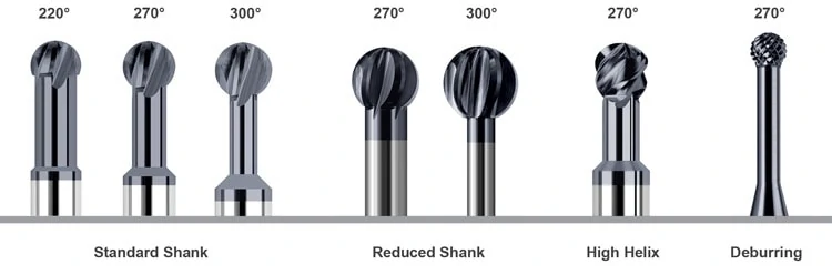
Exactly what tool to use depends on the geometry of the feature and the part. These tools are available with a range of wrap angles like 220°, 270°, and 300°. Greater wrap angles are the result of a thinner neck and create a more spherical cutting end. This style offers more clearance at the cost of rigidity. Likewise, undercutting end mills with lower wrap angles sacrifice clearance for greater rigidity.
Deburring & Edgebreaking
Since undercuts have a wrap angle that is greater than 180°, they are very well-suited to deburring or edgebreaking anywhere on your workpiece, including the underside. Deburring your parts by hand can be inefficient for your shop – using an undercutting end mill instead will save you time and money. Edgebreaking operations are often a critical final step to create a part that looks and feels like a finished product and that is safe to handle.
All undercutting end mills can be used to deburr and edgebreak, which makes them a useful tool to have on hand in any shop. Some manufacturers also offer specialized deburring tools that are designed with a right and left hand flute orientation, giving them “teeth” that make them particularly useful for deburring complex shapes. Using a deburring tool in a 5-axis machine often makes it possible to deburr or edgebreak an entire workpiece in one shot.
Slotting
Most machinists might not think of undercutting end mills for slotting, but they are fully capable of this operation. An equivalent slot can be machined with a regular ball end mill, but doing so might not be feasible due to clearance issues – an undercutter has a reduced neck, unlike a standard ball end mill. Additionally, using an undercutter to slot can save time switching to an equivalent ball end mill.
Since only 180° of the cutting end can be used to slot, undercutting end mills with lower wrap angles and thicker necks are best suited to slotting. However, high helix undercutting tools may be ideal if improved finish and increased chip removal are important to the operation.
Contouring & Profiling
With their wrap angle and increased clearance, undercutting end mills are very useful for both simple and complicated contouring and profiling operations. Their versatility means that it is sometimes possible to accomplish the entire operation with a single tool, rather than several, especially when 5-axis milling.
Reduced shank tools offer the most versatility in complex contouring and profiling operations. The ability to chuck these tools at any depth means that they are capable of maximum clearance.
Choosing An Undercutting End Mill
While most undercutting end mills are conceptually similar, there are a few key differences that must be considered when picking the right tool for your job. Harvey Tool offers the following styles as stock standard tools.
https://www.harveyperformance.com/wp-content/uploads/2017/08/Feature-Image-Undercutting-IMG.jpg5251400Harvey Performance Companyhttp://www.harveyperformance.com/wp-content/uploads/2018/08/Logo_HarveyPerformanceCompany-4.pngHarvey Performance Company2017-08-16 16:00:002024-02-12 14:46:18Undercutting End Mills: Well-Rounded Tools That Offer Maximum Versatility
We use cookies to ensure that we give you the best experience on our website. If you continue to use this site we will assume that you are happy with it.Ok