Tag Archive for: Chip Evacuation

How Material Specific Tooling Pays Off

A machinist is faced with many questions while selecting the proper tool for their job. One key decision that must be made is whether a material specific tool is appropriate and necessary for the application that’s going to be performed – whether the benefits of using this type of tool outweigh the higher price tag than that of a tool designed for use in a variety of materials. There are four main categories to consider when deciding whether a material specific tool is your best bet: internal tool geometry, coatings, material removal rates (MRR), and cost.

When to Utilize Material Specific Tooling

Are you a machinist in a shop that deals primarily with one type of material? Or, do you generally change materials frequently throughout the day? Further, how many parts do you make at a time? These are questions you must ask yourself prior to making a tooling decision.

Material Specific Tooling is best utilized where several parts are being machined of the same material. For instance, if your shop is machining 1,000 plastic parts, it would be in your best interest to opt for a tool designed for this material as your tooling would not only last longer but perform better. If machining flexibility is paramount for your shop, if you’re only machining a few parts, or if part finish is not of high importance, a regular end mill may suffice.

Pros and Cons of Material Specific Tooling

There are pros and cons to purchasing a Material Specific Tool.

Pros:

  • Tool geometry designed for the material you’re working in to achieve the best results.
  • Coating optimized for the material you’re cutting.
  • More aggressive speeds and feeds, and boosted MRR as a result.
  • Increased tool life.

Cons:

  • Higher upfront cost, though long term savings are possible if used in proper situations.
  • Less opportunity for flexibility. While most end mills may be suitable for use in many jobs and many machines, Material Specific End Mills are engineered for use in specific materials

Special Benefits of Material Specific Tooling

A Unique Internal Tool Geometry

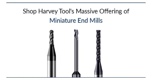
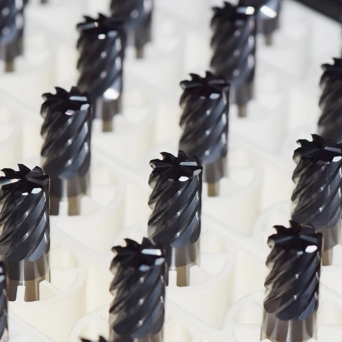
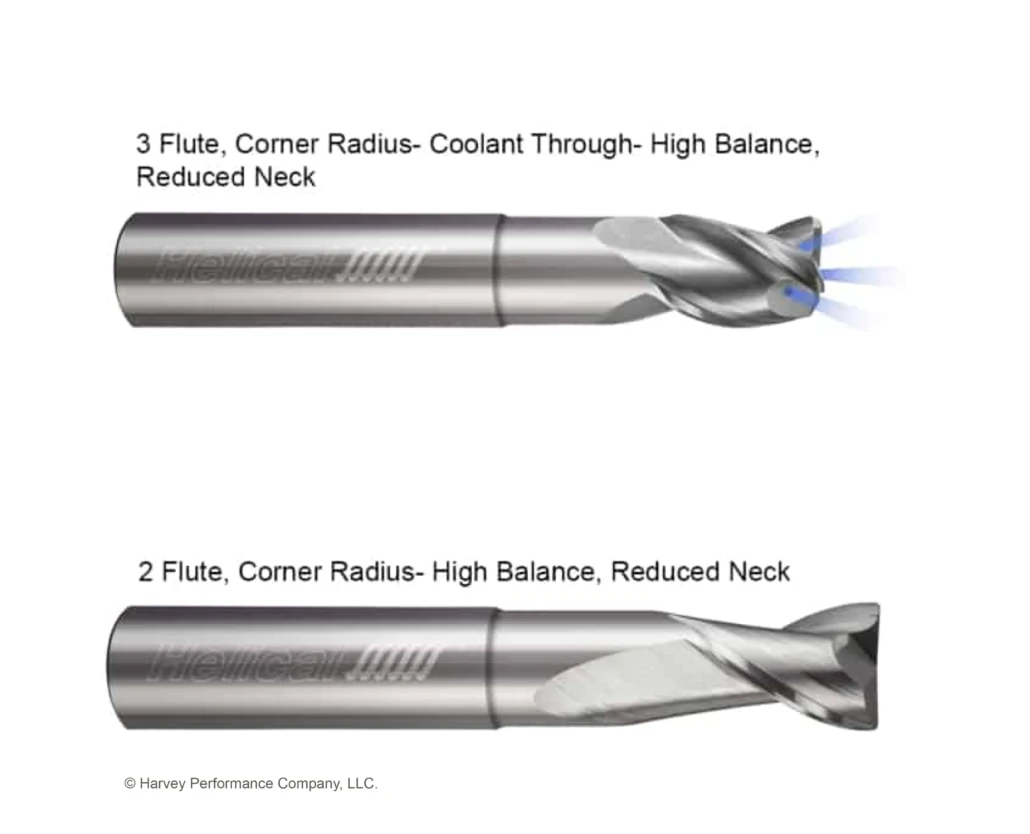
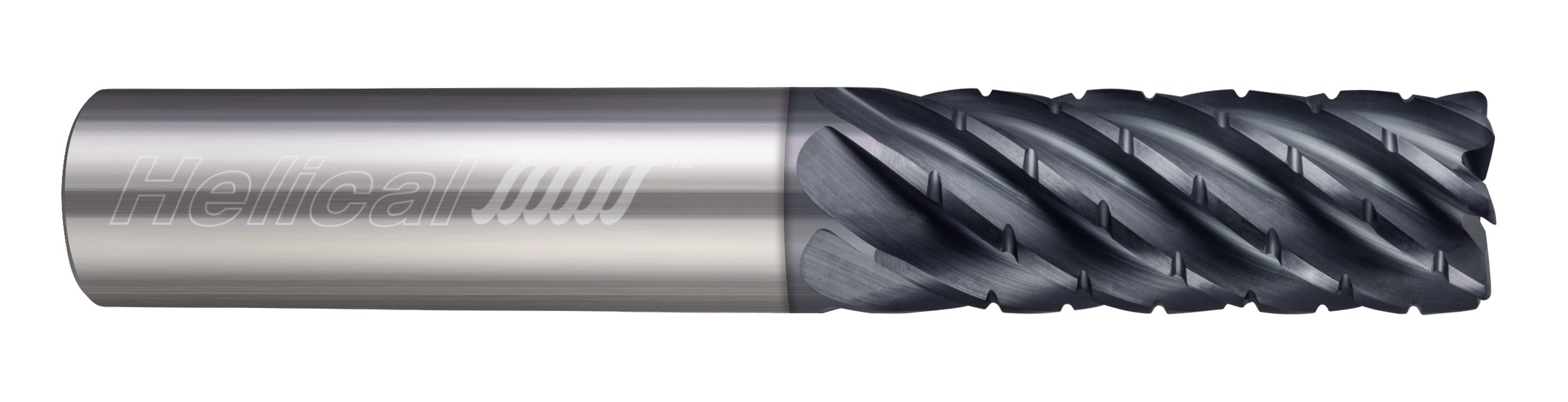
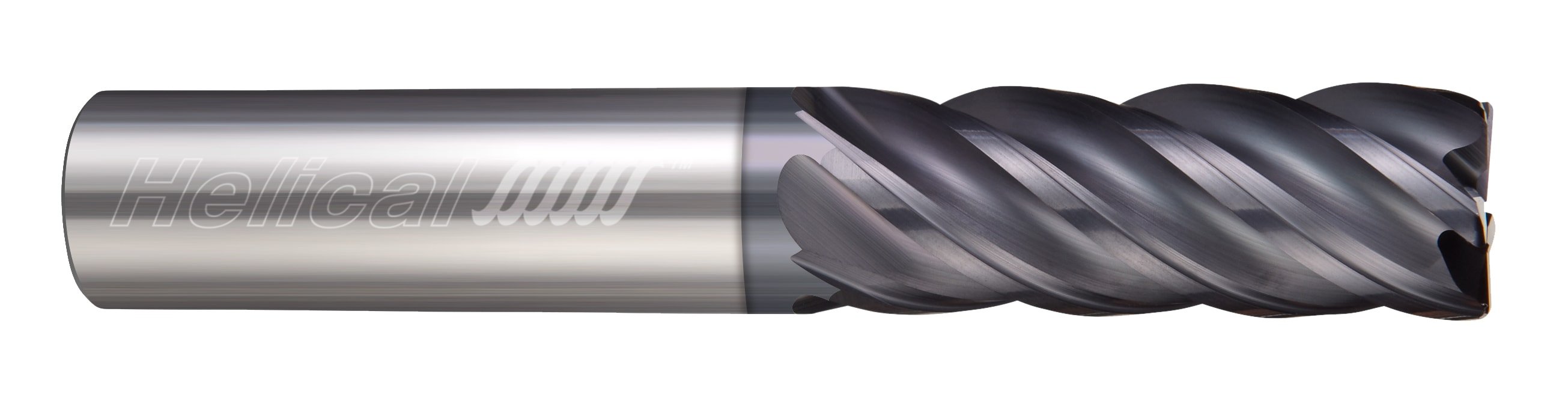
Many manufacturers supply tooling designed for use in specific material buckets. For instance, Harvey Tool has distinct catalog sections for material specific tooling for Hardened Steels, Exotic Alloys, Medium Alloy Steels, Free Machining Steels, Aluminum Alloys, Plastics, Diamond Tooling for Non-Ferrous Materials, and Composites. The special geometry of tools found in these sections is optimized to allow the tool to perform optimally in its select material group.

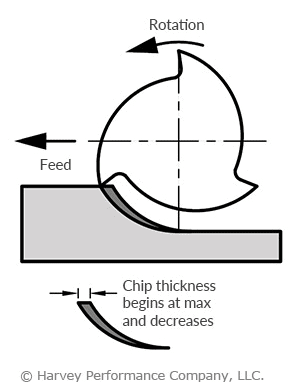
For instance, a machinist may be faced with a dilemma while preparing to machine a plastic part. While an end mill found in Harvey Tool’s Miniature End Mill section could certainly machine this material, Harvey Tool’s end mill offering designed to machine plastics feature a high rake, high relief design. This is ideal for plastics because you want to effectively cut and form chips while the strength of the tool is less of a concern. The high rake and high relief creates a sharp cutting edge that would quickly break down in metals. However, in plastics, this effectively shears the material and transfers the heat into the chip to produce a great finish in your part.

single flute end mill for pastics

Harvey Performance Company, LLC.

Specific Coatings & Substrates for Optimal Performance

One key benefit of opting for a material specific tool is the ability to utilize the best coating option available for that material. Tool coatings serve many functions, including improved lubricity, increased tool life, and a higher-quality part finish. In addition, coated tools can typically be run around 10% faster than uncoated tools.

While many manufacturers will specially coat a standard end mill at your request, this takes added time and cost. In its Material Specific catalog sections, Harvey Tool offers coated tools stocked and ready to ship. For instance, their Hardened Steels and Exotic Alloys categories utilize AlTiN Nano coating. This is a unique nanocomposite coating that has a max working temperature of 2,100° F and shows improved performance in materials such as Hardened Steels, Titanium Alloys, and Inconel, among others.

Increased Material Removal Rates

Because Material Specific Tooling features optimal tool geometry for a job, running parameters are generally able to be more aggressive. Any machinist knows that Material Removal Rates (MRR), is the metric that’s most closely related to shop efficiency, as the more material removed from a part in a given period of time, the faster parts are made and the higher the shop output.

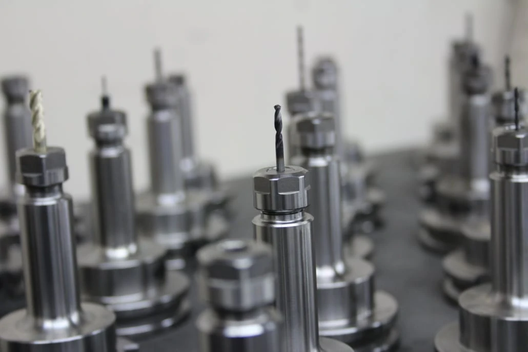
The following example compares running parameters of end mills from Harvey Tool’s Miniature End Mill and Material Specific End Mill Sections. You can notice that while key geometries between the two tools are identical, and are in use in the same material with the same operation, the chip load (+25%), linear feed rate (+33%), and depth of cut (+43%) are boosted. This allows for more material to be removed in a shorter period of time.

Miniature End Mill

Part Number: 836408

Description: 3 Flute 1/8 inch diameter 3x LOC Square Stub & Standard

Material: 6061 Aluminum

Application: Slotting

Speed: 10,000 RPM

Chip Load: .00124 IPT

Linear Feed: 37.2 IPM

DOC: .04375

harvey tool miniature end mill

Material Specific End Mill

Part Number: 942308

Description: 3 Flute 1/8 inch diameter 3x LOC Square Variable Helix for Aluminum Alloys

Material: 6061 Aluminum

Application: Slotting

Speed: 10,000 RPM

Chip Load: .00165 IPT

Linear Feed: 49.5 IPM

DOC: .0625

harvey tool miniature variable helix end mill

Harvey Performance Company, LLC.

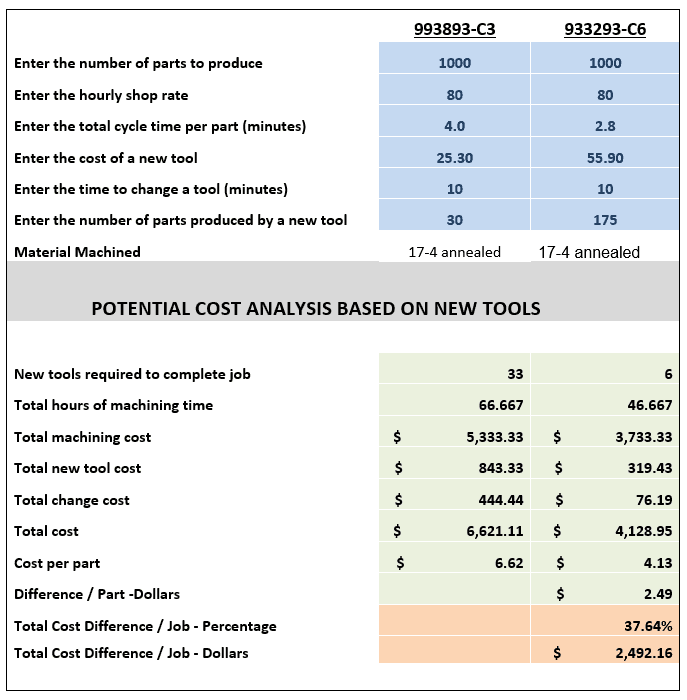
Extensive Cost Savings

The following chart displays a cost analysis breakdown between a tool found in the Miniature End Mill section, item 993893-C3; and a tool found in the Material Specific End Mill section, item 933293-C6. When compared for the machining of 1,000 parts, the overall savings is nearly $2,500.

material specific tooling benefit chart in cost savings

Material Specific Tooling Summarized

In conclusion, Material Specific End Mills have many benefits, but are best utilized in certain situations. While the initial cost of these tools are higher, they can work to save your shop time and money in the long run by lasting longer and producing more parts over a given period of time.

Confidently Select Your Next Thread Mill

Do you know the key differences between a Single Form Thread Mill and a Multi-Form version? Do you know which tooling option is best for your job? This blog post examines how several factors, including the tool’s form and max depth of thread, are important to ultimately making the appropriate Harvey Tool decision.

Thread Mill Product Offering

Single Form

The single form thread mill is the most versatile threading solution Harvey Tool offers. These tools are ground to a sharp point and are capable of milling 60° thread styles, such as UN, metric, and NPT threads. With over 14 UN and 10 Metric sized tools, Harvey Tool’s single form selections allow machinists the opportunity to machine many different types of threads.

single form harvey tool thread mill

Harvey Performance Company, LLC.

Single Form Thread Mills for Hardened Steels

Similar to the standard single form, Harvey Tool’s thread mills for hardened steels offer machinists a quality option when dealing with hardened steels from 46-68 Rc. The following unique geometries helps this tool machine tough alloys:

  1. Ground Flat – Instead of a sharp point these tools have a ground flat to help ensure long tool life.
  2. Eccentric Relief – Gives the cutting edges extra strength for the high feeds at relatively low RPMs required for harder materials.
  3. AlTiN Nano Coating – Allows for superior heat resistance.
single form thread mill for hardened steels

Harvey Performance Company, LLC.

A key difference between the standard Single Form and the Single Form for Hardened Steels is that the tools for hardened steels are actually only capable of milling 83% of the actual thread depth. At first, this may seem detrimental to your operation. However, according to the Machinery’s Handbook 29th Edition, “Tests have shown that any increase in the percentage of full thread over 60% does not significantly increase the strength of the thread. Often, a 55% to 60% thread is satisfactory, although 75% threads are commonly used to provide an extra margin of safety.” With the ability to preserve tool life and effectively perform thread components, Harvey Tool’s single form thread mills for hardened steels are a natural choice when tackling a hardened material.

Tri-Form

Tri-Forms are designed for difficult-to-machine materials. The tri-form design reduces tool pressure and deflection, which results in more accurate threading. Its left-hand cut, left-hand spiral design allows it to climb mill from the top of the thread to the bottom.

tri form thread mill from harvey tool

Harvey Performance Company, LLC.

Multi-Form

Our multi-form thread mills are offered in styles such as UN, NPT, and Metric. Multi-Form tools are optimized to produce a full thread in single helical interpolation. Additionally, they allow a machinist to quickly turn around production-style jobs.

multi-form thread mill

Harvey Performance Company, LLC.

Coolant-Through Multi Form Thread Mills

Coolant-Through Multi Form Thread Mills are the perfect tool for when a job calls for thread milling in a blind hole. The coolant through ability of the tool produces superior chip evacuation. These tools also improve coolant flow to the workpiece – delivering it directly from the tip of the tool – for decreased friction and high cutting speeds.

coolant through multi form thread mill

Harvey Performance Company, LLC.

Long Flute

These tools are great when a job calls for a deep thread, due to their long flute. Long Flutes also have a large cutter diameter and core, which provides the tool with improved tool strength and stability.

long flute harvey tool thread mill

Harvey Performance Company, LLC.

N.P.T. Multi-Form

While it may seem obvious, N.P.T. Multi-Form Thread Mills are perfect for milling NPT threads. NPT threads are great for when a part requires a full seal, different from traditional threads that hold pieces together without the water-tight seal.

npt thread mill from harvey tool

Harvey Performance Company, LLC.

Effective Ways to Reduce Heat Generation

Any cutting tool application will generate heat, but knowing how to counteract it will improve the life of your tool. Heat can be good and doesn’t need to totally be avoided, but controlling heat will help prolong your tool life. Sometimes, an overheating tool or workpiece is easy to spot due to smoke or deformation. Other times, the signs are not as obvious. Taking every precaution possible to redirect heat will prolong your tool’s usable life, avoid scrapped parts, and will result in significant cost savings.

Reduce Heat Generation with HEM Tool Paths

High Efficiency Milling (HEM), is one way a machinist should explore to manage heat generation during machining. HEM is a roughing technique that uses the theory of chip thinning by applying a smaller radial depth of cut (RDOC) and a larger axial depth of cut (ADOC). HEM uses RDOC and ADOC similar to finishing operations but increases speeds and feeds, resulting in greater material removal rates (MRR). This technique is usually used for removing large amounts of material in roughing and pocketing applications. HEM utilizes the full length of cut and more effectively uses the full potential of the tool, optimizing tool life and productivity. You will need to take more radial passes on your workpiece, but using HEM will evenly spread heat across the whole cutting edge of your tool, instead of building heat along one small portion, reducing the possibility of tool failure and breakage.

heat generation in standard versus hem milling and their associated depths of cut

Chip Thinning Awareness

Chip thinning occurs when tool paths include varying radial depths of cut, and relates to chip thickness and feed per tooth. HEM is based off of the principal of chip thinning. However, if not properly executed, chip thinning can cause a lot of heat generation. When performing HEM, you effectively reduce your stepover and increase your speeds and feeds to run your machine at high rates. But if your machine isn’t capable of running high enough speeds and feeds, or you do not adjust accordingly to your reduced stepover, trouble will occur in the form of rubbing between the material and tool. Rubbing creates friction and mass amounts of heat which can cause your material to deform and your tool to overheat. Chip thinning can be good when used correctly in HEM, but if you fall below the line of reduced stepover without higher speeds and feeds, you will cause rubbing and tool failure. Because of this, it’s always important to be aware of your chips during machining.

infographic showcasing chip thinning in relation to step over

Consider Climb Milling

There are two ways to cut materials when milling: conventional milling and climb milling. The difference between the two is the relationship of the rotation of the cutter to the direction of feed. In climb milling, the cutter rotates with the feed, as opposed to conventional milling where the cutter rotates against the feed.

When conventional milling, chips start at theoretical zero and increase in size, causing rubbing and potentially work hardening. For this reason, it’s usually recommended for tools with higher toughness or for breaking through case hardened materials.

In climb milling, the chip starts at maximum width and decreases, causing the heat generated to transfer into the chip instead of the tool or workpiece. When going from max width to theoretical zero, heat will be transferred to the chip and pushed away from the workpiece, reducing the possibility of damage to the workpiece. Climb milling also produces a cleaner shear plane which will cause less tool rubbing, decreasing heat and improving tool life. When climb milling, chips are removed behind the cutter, reducing your chances of re-cutting. climb milling effectively reduces heat generated to the tool and workpiece by transferring heat into the chip, reducing rubbing and by reducing your chances of re-cutting chips.

infographic showing climb versus conventional milling in feed path and end mill direction

Utilize Proper Coolant Methods

If used properly, coolant can be an extremely effective way to keep your tool from excessive heat generation. There are many different types of coolant and different ways coolant can be delivered to your tool. Coolant can be compressed air, water-based, straight oil-based, soluble oil-based, synthetic or semi-synthetic. It can be delivered as mist, flood, high pressure or minimum quantity lubricant.

Different applications and tools require different types and delivery of coolant, as using the wrong delivery or type could lead to part or tool damage. For instance, using high pressure coolant with miniature tooling could lead to tool breakage. In materials where chip evacuation is a major pain point such as aluminum, coolant is often used to flush chips away from the workpiece, rather than for heat moderation. When cutting material that produces long, stringy chips without coolant, you run the risk of creating built-up edge from the chips evacuating improperly. Using coolant will allow those chips to slide out of your toolpath easily, avoiding the chance of re-cutting and causing tool failure. In materials like titanium that don’t transfer heat well, proper coolant usage can prevent the material from overheating. With certain materials, however, thermal shock becomes an issue. This is when coolant is delivered to a very hot material and decreases its temperature rapidly, impacting the material’s properties. Coolant can be expensive and wasteful if not necessary for the application, so it’s important to always make sure you know the proper ways to use coolant before starting a job.

Importance of Controlling Heat Generation

Heat can be a tool’s worst nightmare if you do not know how to control it. High efficiency milling will distribute heat throughout the whole tool instead of one small portion, making it less likely for your tool to overheat and fail. By keeping RDOC constant throughout your toolpath, you will decrease the chances of rubbing, a common cause of heat generation. Climb milling is the most effective way to transfer heat into the chip, as it will reduce rubbing and lessen the chance of re-chipping. This will effectively prolong tool life. Coolant is another method for keeping temperatures moderated, but should be used with caution as the type of coolant delivery and certain material properties can impact its effectiveness.

5 Questions to Ask Before Selecting an End Mill

Few steps in the machining process are as important as proper end mill selection. Complicating the process is the fact that each individual tool has its own unique geometries, each pivotal to the eventual outcome of your part. We recommend asking yourself 5 key questions before beginning the tool selection process. In doing so, you can ensure that you are doing your due diligence in selecting the best tool for your application. Taking the extra time to ensure that you’re selecting the optimal tool will reduce cycle time, increase tool life, and produce a higher quality product.

Question 1: What Material Am I Cutting?

Knowing the material you are working with and its properties will help narrow down your end mill selection considerably. Each material has a distinct set of mechanical properties that give it unique characteristics when machining. For instance, plastic materials require a different machining strategy – and different tooling geometries – than steels do. Choosing a tool with geometries tailored towards those unique characteristics will help to improve tool performance and longevity.

Harvey Tool stocks a wide variety of High Performance Miniature End Mills. Its offering includes tooling optimized for hardened steels, exotic alloys, medium alloy steels, free machining steels, aluminum alloys, highly abrasive materials, plastics, and composites. If the tool you’re selecting will only be used in a single material type, opting for a material specific end mill is likely your best bet. These material specific tools provide tailored geometries and coatings best suited to your specific material’s characteristics. But if you’re aiming for machining flexibility across a wide array of materials, Harvey Tool’s miniature end mill section is a great place to start.

Shop Harvey Tool’s Massive Offering of Fully Stocked Miniature End Mills

Helical Solutions also provides a diverse product offering tailored to specific materials, including Aluminum Alloys & Non-Ferrous Materials; and Steels, High-Temp Alloys, & Titanium. Each section includes a wide variety of flute counts – from 2 flute end mills to Multi-Flute Finishers, and with many different profiles, coating options, and geometries.

Question 2: Which Operations Will I Be Performing?

An application can require one or many operations. Common machining operations include:

  • Traditional Roughing
  • Slotting
  • Finishing
  • Contouring
  • Plunging
  • High Efficiency Milling

By understanding the operations(s) needed for a job, a machinist will have a better understanding of the tooling that will be needed. For instance, if the job includes traditional roughing and slotting, selecting a Helical Solutions Chipbreaker Rougher to hog out a greater deal of material would be a better choice than a Finisher with many flutes.

Question 3: How Many Flutes Do I Need?

One of the most significant considerations during end mill selection is determining proper flute count. Both the material and application play an important role in this decision.

Material:

When working in Non-Ferrous Materials, the most common options are the 2 or 3-flute tools. Traditionally, the 2-flute option has been the desired choice because it allows for excellent chip clearance. However, the 3-flute option has proven success in finishing and High Efficiency Milling applications, because the higher flute count will have more contact points with the material.

Ferrous Materials can be machined using anywhere from 3 to 14-flutes, depending on the operation being performed.

Application:

Traditional Roughing: When roughing, a large amount of material must pass through the tool’s flute valleys en route to being evacuated. Because of this, a low number of flutes – and larger flute valleys – are recommend. Tools with 3, 4, or 5 flutes are commonly used for traditional roughing.

Slotting: A 4-flute option is the best choice, as the lower flute count results in larger flute valleys and more efficient chip evacuation.

Finishing: When finishing in a ferrous material, a high flute count is recommended for best results. Finishing End Mills include anywhere from 5-to-14 flutes. The proper tool depends on how much material remains to be removed from a part.

High Efficiency Milling: HEM is a style of roughing that can be very effective and result in significant time savings for machine shops. When machining an HEM toolpath, opt for 5 to 7-flutes.

graphic showcasing the tool face of end mills from 2 to 12 flutes

Question 4: What Specific Tool Dimensions are Needed?

After specifying the material you are working in, the operation(s) that are going to be performed, and the number of flutes required, the next step is making sure that your end mill selection has the correct dimensions for the job. Examples of key considerations include cutter diameter, length of cut, reach, and profile.

Cutter Diameter

The cutter diameter is the dimension that will define the width of a slot, formed by the cutting edges of the tool as it rotates. Selecting a cutter diameter that is the wrong size – either too large or small – can lead to the job not being completed successfully or a final part not being to specifications.  For example, smaller cutter diameters offer more clearance within tight pockets, while larger tools provide increased rigidity in high volume jobs.

Length of Cut & Reach

The length of cut needed for any end mill should be dictated by the longest contact length during an operation. This should be only as long as needed, and no longer. Selecting the shortest tool possible will result in minimized overhang, a more rigid setup, and reduced chatter. As a rule of thumb, if an application calls for cutting at a depth greater than 5x the tool diameter, it may be optimal to explore necked reach options as a substitute to a long length of cut.

Tool Profile

The most common profile styles for end mills are square, corner radius, and ball. The square profile on an end mill has flutes with sharp corners that are squared off at 90°. A corner radius profile replaces the fragile sharp corner with a radius, adding strength and helping to prevent chipping while prolonging tool life. Finally, a ball profile features flutes with no flat bottom, and is rounded off at the end creating a “ball nose” at the tip of the tool. This is the strongest end mill style.  A fully rounded cutting edge has no corner, removing the mostly likely failure point from the tool, contrary to a sharp edge on a square profile end mill. An end mill profile is often chosen by part requirements, such as square corners within a pocket, requiring a square end mill.  When possible, opt for a tool with the largest corner radius allowable by your part requirements. We recommend a corner radii whenever your application allows for it. If square corners are absolutely required, consider roughing with a corner radius tool and finishing with the square profile tool.

end mill graphic with dimension callouts

Question 5: Should I Use a Coated Tool?

When used in the correct application, a coated tool will help to boost performance by providing the following benefits:

  • More Aggressive Running Parameters
  • Prolonged Tool life
  • Improved Chip Evacuation

Harvey Tool and Helical Solutions offer many different coatings, each with their own set of benefits. Coatings for ferrous materials, such as AlTiN Nano or TPlus, typically have a high max working temperature, making them suitable for materials with a low thermal conductivity. Coatings for non-ferrous applications, such as TiB2 or ZPlus, have a low coefficient of friction, allowing for easier machining operations. Other coatings, such as Amorphous Diamond or CVD Diamond Coatings, are best used in abrasive materials because of their high hardness rating.

multiple end mills after being coated, zoomed in on cutting faces

Ready to Decide on an End Mill

There are many factors that should be considered while looking for the optimal tooling for the job, but asking the aforementioned five key question during the process will help you to make the right decision. As always, The Harvey Performance Company Technical Service Department is always available to provide recommendations and walk you through the tool selection process, if need be.

Harvey Tool Technical Support: 800-645-5609

Helical Solutions Technical Support: 866-543-5422

Experience the Benefits of Staggered Tooth Keyseats

Keyseat Cutters, also known as Woodruff Cutters, Keyway Cutters, and T-Slot Cutters, are commonly used in machine shops. Many machinists opt to use this tool to put a slot on the side of a part in an efficient manner, rather than rotating the workpiece and using a traditional end mill. A Staggered Tooth Keyseat Cutter has alternating right-hand and left hand shear flutes and is right-hand cut, whereas a traditional keyseat cutter has all straight flutes and is right-hand cut. Simply, the unique geometry of a Staggered Tooth Keyseat Cutter gives the tool its own set of advantages including the ability to index within the slot, increase feed rates, and achieve better part finish.

face of a staggered tooth keyseat cutter

Three Key Benefits

Indexing

The alternating right-and-left-hand flutes of a Harvey Tool Staggered Tooth Keyseat Cutters are relieved on both sides of its head, meaning that it allows for both end cutting and back cutting. This adds to the versatility of the staggered tooth keyseat cutter, where one singular tool can be indexed axially within a slot to expand the slot to a specific uncommon dimension. This can save space in a machinist’s magazine and reduce machine time by eliminating the need to swap to a new tool.

Increased Feed Rates

Due to the unique geometry of a Staggered Tooth Keyseat Cutter, chips evacuate efficiently and at a faster rate than that of a Straight Flute Keyseat Cutter. The unique flutes of Staggered Tooth Keyseat Cutters are a combination of right-and-left-hand shear flutes, but both types are right-hand cutting. This results in the tool’s teeth alternating between upcut and downcut. Chip packing and chip recutting is less of a concern with running this tool, and results in increased chip loads compared to that of a standard keyseat with the same number of flutes. Because of this, the tool can account for chiploads of about 10% higher than the norm, resulting in heightened feed rates and shorter cycle times overall.

Better Part Finish

Staggered Tooth Keyseat Cutters have “teeth”, or flutes, that are ground at an angle creating a shear flute geometry. This geometry minimizes chip recutting, chip dragging and reduces the force needed to cut into the material. Chip recutting and dragging are minimized because chips are evacuated out of the top and bottom of the head on the side of the cutter that is not engaged in the material. Shear flutes also reduce vibrations that can lead to chatter and poor finish. By minimizing cutting forces, vibration, and chatter, a machinist can expect a better part finish.

staggered tooth keyseat cutter working in a cnc machine

Image courtesy of @edc_machining

Staggered Tooth Keyseat Cutter Diverse Product Offering

On top of the higher performance one will experience when using the Stagger Tooth Keyseats, there are also multiple options available with various combinations to suit multiple machining needs. This style is offered in a square, square reduced shank and corner radius profile which helps if a fillet or sharp corner is needed. The square and corner radius tools are offered in diameters ranging from 1/8” to 5/8”, and the square reduced shank tool is offered in diameteres ranging from 3/4″ to 1-1/2″. The increased diameter comes with an increase of radial depth of cut, allowing deeper slots to be achievable. Within the most popular cutter diameters, ¼”, 3/8”, and ½” there are also deep slotting options with even greater radial depth of cuts for increased slot depths. On top of the diameters and radii, there are also multiple cutter widths to choose from to create different slots in one go. Finally, an uncoated and AlTiN coatings are available to further increase tool life and performance depending on the material that is being cut.

Opt for a Smoother Operation

A Staggered Tooth Keyseat Cutter adds versatility to a tool magazine. It can be indexed axially to expand slots to make multiple widths, allowing machinists to progress operations in a more efficient manner where tool changes are not required. Further, this tool will help to reduce harmonics and chatter, as well as minimize recutting. This works to create a smoother operation with less force on the cutter, resulting in a better finish compared to a Standard Keyseat Cutter.

For more information on Harvey Tool Staggered Tooth Keyseat Cutters and its applications, visit Harvey Tool’s Keyseat Cutter page.

B&R Custom Machining- Featured Customer

Featured Image Courtesy of B&R Custom Machining

B&R Custom Machining is a rapidly expanding aerospace machine shop located in Ontario, Canada, focused primarily on aerospace and military/defense manufacturing. Over the past 17 years, B&R has grown from a 5 person shop with a few manual mills and lathes, into one of Canada’s most highly respected manufacturing facilities, with nearly 40 employees and 21 precision CNC machines.

B&R focuses on quality assurance and constant improvement, mastering the intimacies of metal cutting and maintaining the highest levels of quality through their unique shop management philosophies. They seek to consistently execute on clear contracts through accurate delivery, competitive price, and high quality machined components.

We talked with Brad Jantzi, Co-Founder and Technical Manager of B&R Custom Machining, to learn about how he started in the industry, his experience with High Efficiency Milling, what he looks for most in a cutting tool, and more!

B&R Custom machining

Photo Courtesy of: B&R Custom Machining

Can you tell us a little bit about how B&R Custom Machining started, and a little background about yourself and the company?

My brother (Ryan Jantzi, CEO/Co-Founder) and I started working in manufacturing back in 2001, when we were just 20/21 years old. We had 5 employees (including ourselves), a few manual mills and lathes, and we were wrapping our parts in newspaper for shipping. We took over from a preexisting shop and assumed their sales and machines.

We bought our first CNC machine in 2003, and immediately recognized the power of CNC and the opportunities it could open up for us. Now, we have 21 CNC machines, 38 employees, and more requests for work than we can keep up with, which is a good thing for the business. We are constantly expanding our team to elevate the business and take on even more work, and are currently hiring for multiple positions if anyone in Ontario is looking for some challenging and rewarding work!

What kind of CNC machines are you guys working with?

Right now we have a lot of Okuma and Matsuura machines, many of which have 5 axis capabilities, and all of them with high RPM spindles. In fact, our “slowest” machine runs at 15k RPM, with our fastest running at 46k. One of our high production machines is our Matsuura LX160, which has the 46k RPM spindle. We use a ton of Harvey Tool and Helical product on that machine and really get to utilize the RPMs.

B&R Custom Machining

Photo Courtesy of: B&R Custom Machining

What sort of material are you cutting?

We work with Aluminum predominantly, but also with a lot of super alloys like Invar, Kovar, Inconel, Custom 455 Stainless, and lots of Titanium. Some of those super alloys are really tricky stuff to machine. Once we learn about them and study them, we keep a recorded database of information to help us dial in parameters. Our head programmer/part planner keeps track of all that information, and our staff will frequently reference old jobs for new parts.

Sounds like a great system you guys have in place. How did B&R Custom Machining get into aerospace manufacturing?

It is a bit of a funny story actually. Just about 12 years ago we were contacted by someone working at Comdev, which is close to our shop, who was looking to have some parts made. We started a business relationship with him, and made him his parts. He was happy with the work, and so we eventually got involved in his company’s switch division and started to make more and more aerospace parts.

aerospace machining

Photo Courtesy of: B&R Custom Machining

We immediately saw the potential of aerospace manufacturing, and it promoted where we wanted to go with CNC machining, so it was a natural fit. It really was a case of being in the right place at the right time and seizing the moment. If an opportunity comes up and you aren’t ready for it, you miss it. You have to be hungry enough to see an opportunity, and confident enough to grab it, while also being competent enough to handle the request. So, we took advantage of what we were given, and we grew and went from there.

Who are some of the major players who you work with?

We have great relationships with Honeywell, MDA Brampton, and MDA Quebec. We actually worked on parts for a Mars Rover with MDA that was commissioned by the Canadian Space Agency, which was really cool to be a part of.

Working with large companies like that means quality is key. Why is high quality tool performance important to you?

High quality and superior tool performance is huge. Aside from cutting conditions, there are two quick things that cause poor performance on a tool: tool life and consistency of the tool quality. One without the other means nothing. We all can measure tool life pretty readily, and there is a clear advantage that some tools have over others, but inconsistent quality can sneak up on you and cause trouble. If you have a tool manufacturer that is only producing a quality tool even 95% of the time, that might seem ok, but that means that 5% of the time you suffer something wrong on the machine. Many times, you won’t know where that trouble is coming from. This causes you to pause the machine, investigate, source the problem, and then ultimately switch the tool and create a new program. It becomes an ordeal. Sometimes it is not as simple as manually adjusting the feed knob, especially when you need to rely on it as a “proven program” the next time around.

So, say the probability of a shortcoming on a machine is “x” with one brand of tooling, but is half of that with a brand like Harvey Tool. Sure, the Harvey Tool product might be 10-20% higher in upfront cost, but that pales in comparison to buying cheaper tools and losing time and money due to machine downtime caused by tool failure. The shop rate for an average machine is right around $100/hour, so machine downtime is much more expensive than the added cost of a quality tool.

B&R Custom machining

Photo Courtesy of: B&R Custom Machining

Inconsistent tool quality can be extremely dangerous to play around with, even outside of machine downtime. We create based on a specific tool and a certain level of expected performance. If that tool cannot be consistent, we now jeopardize an expensive part. The machine never went down, but the part is no good because we programmed based on consistency in tool quality. Again, the cost of scrapped parts heavily outweighs the upfront cost of quality tooling. Tooling is a low cost of what we do here, but poor tooling can cost us thousands versus a few dollars more for quality tools. Too many people focus on the upfront cost, and don’t look downstream through the rest of the process to see how poor quality tooling can affect your business in a much bigger way. We get to see the whole picture because I am involved from cradle to grave, gaining feedback and knowledge along the way.

That’s great feedback Brad, and I think it is important for people to understand what you have laid out here. Speaking of tool performance, have you guys been using High Efficiency Milling techniques in the shop?

Absolutely. We feel that we are on the front edge of efficient milling. We are quite capable of all the latest techniques, as our programmers are well-versed and up to date. For our larger production work, we have programs dialed in that allow us to push the tools to their limits and significantly cut down our cycle times.

What advice would you have for others who are interested in High Efficiency Milling?

Make sure you are smart about using HEM. If we have one-off parts, particularly expensive ones, that do not have time restraints, we want to make sure we have a safe toolpath that will get us the result we want (in terms of quality and cutting security), rather than pushing the thresholds and taking extra time to program the HEM toolpaths. HEM makes total sense for large production runs, but make sure you know when to, and when not to use these techniques to get the most out of HEM.

B&R Custom machining

Photo Courtesy of: B&R Custom Machining

Have you been using Machining Advisor Pro in your shop when you run Helical end mills?

We have been, and it makes for a great point of reference for the Helical end mills. It has become a part of our new employee training, teaching them about speeds and feeds, how hard they can push the Helical tools, and where the safe zones are. Our more experienced guys also frequent it for new situations where they have no data. Machining Advisor Pro helps to verify what we thought we knew, or helps us get the confidence to start planning for a new job.

If you could give one piece of advice to a new machinist, or someone looking to take the #PlungeIntoMachining for the first time, what would it be?

Learn the intimacies of metal cutting. Get ultra-familiar with the results of what is actually happening with your tool, your setup, your part, and your machine. As well, don’t be limited to thinking “it sounds good,” or “it’s going good so far, so that must be acceptable.” In order to push the tools and confirm they are performing well and making money, you need to identify and understand where the threshold of failure is, and back off the right amount. This doesn’t end here though. Cutting conditions change as the tools, holders, machines, and parts change. Learning the nuances of this fluctuating environment and adapting accordingly is essential. Verify your dimensions, mitigate against risk, and control the variables.

Also, get intimate with what causes tools to succeed and fail, and keep a log of it for reference. Develop a passion for cutting; don’t just punch in and punch out each shift. Here at B&R, we are looking for continuous improvement, and employees who can add value. Don’t stand around all day with your arms folded, but keep constant logs of what’s going on and always be learning and thinking of how to understand what is happening, and improve on it. That is what makes a great machinist, and a successful shop.

B&R custom machining

Photo Courtesy of: B&R Custom Machining

How to Maximize High Balance End Mills

High speed machining is becoming increasingly widespread in machine shops all over the world due to the proven benefits of greater efficiency and productivity through increased spindle speeds and metal removal rates.  However, at such high spindle speeds, otherwise negligible errors and imperfections can cause negative effects such as reduced tool life, poor surface finish, and wear on the machine itself. Many of these negative effects stem from an increase in total centrifugal forces leading to vibration, commonly referred to in the industry as chatter. A key contributor to vibrations and one of the more controllable factors, is tool unbalance.

Why Balance is Critical to Machining

Unbalance is the extent to which the tool’s center of mass diverges from its axis of rotation.  Small levels of unbalance may be indistinguishable at lower RPMs, but as centrifugal force increases, small variations in the tool’s center of mass can cause substantial detrimental effects on its performance. High Balance End Mills are often used to help solve the problem of vibrations at the increased spindle speeds. Balancing is used to make compensation for the intrinsic unsymmetrical distribution of mass, which is typically completed by removing mass of a calculated amount and orientation.

infographic showcasing all aspects axii for high balance machining

Image Source: Haimer; Fundamentals of Balancing

Helical Solutions offers High Balance End Mills in both 2 and 3 flute options (see Figure 2), square and corner radius, along with coolant-through on the 3 fluted tools. These end mills are balanced at the industry standard of G2.5 at 33,000 RPM: G stands for the potential damage due to unbalance, which can be expressed as “Balancing Quality Grade” or G and 2.5 is the vibration velocity in MM per second. These tools are designed specifically to increase performance in highly balanced machining centers that are capable of elevated RPMs and feed rates. With high balance tooling, improved surface finishes are also achieved due to reduced vibrations during the machining process. Additionally, these end mills have been designed around current high-end tool holding, and come in a variety of neck lengths at specific overall lengths. These dimensional combinations result in maximum rigidity and reduced excess stick out, allowing for optimal performance and the ability to push the tools to the limit.

cnc high balance end mills in both 2 and 3 flute designs

High Balanced Tooling Cost Benefits

Machinists who choose to use High Balance End Mills will see certain benefits at the spindle, but also in their wallets. Cost benefits of opting to run this type of tool include:

Utilizing Tap Testers

What Tap Testers Do

Vibrations are your applications worst enemy, especially at elevated RPMs and feed rates. Using resources such as a Tap Tester can help decrease vibrations and allow you to get the most out of your High Balance End Mills by generating cutting performance predictions and chatter limits.

How Tap Testing Works

how to properly tap test a cnc tool

Image Source: Manufacturing Automation Laboratories Inc.

Tap Testing generates cutting performance predictions and chatter limits. In a tap test, the machine-tool structure is “excited,” or tested, by being hit with an impulse hammer. In milling, the machine-tool structure is usually flexible in all three directions: X, Y, and Z, but in milling applications where High Balance Tooling is used, the flexibility is commonly only considered in two planes – the X and Y directions. By hitting the X and Y directions with the impulse hammer, the impact will excite the structure over a certain frequency range that is dependent on the hammer’s size, the type of tool being used, and the structure itself. The frequencies generated from the initial hit will produce enough information that both the impact force measurement and the displacement/accelerometer measurement are available. Combining these two measurements will result in the Frequency Response Function, which is a plot of the dynamic stiffness of the structure in frequencies.

After the information from the Tap Test is gathered, it will then process the information into useful cutting parameters for all spindles speeds such as cut depths, speed rates, and feed rates. In knowing the optimum running parameters, vibrations can be minimized and the tool can be utilized to its full potential.

High Balanced Tooling Summarized

Keeping vibrations at bay during the machining process is extremely important to machining success. Because one cause of vibration is tool unbalance, utilizing a balanced tool will result in a smoother job, a cleaner final product, and a longer life of both the tool and spindle. Machinists who choose to use High Balance Tooling can utilize a Tap Tester, or a method for generating the perfect running parameters for your tool and machine setup to ensure that machining vibration is as minimal as possible.

Slaying Stainless Steel: Machining Guide

Stainless steel can be as common as Aluminum in many shops, especially when manufacturing parts for the aerospace and automotive industries. It is a fairly versatile material with many different alloys and grades which can accommodate a wide variety of applications. However, milling steel can also be immensely difficult. Stainless steels are notorious end mill assassins, so dialing in your speeds and feeds and selecting the proper tool is essential for machining success.

stainless steel machining

Material Properties

Stainless steels are high-alloy steels with superior corrosion resistance to carbon and low-alloy steels. This is largely due to their high chromium content, with most grades of stainless steel alloys containing at least 10% of the element.

Stainless steel can be broken out into one of five categories: Austenitic, Ferritic, Martensitic, Precipitation Hardened (PH), and Duplex. In each category, there is one basic, general purpose alloy. From there, small changes in composition are made to the base in order to create specific properties for various applications.

For reference, here are the properties of each of these groupings, as well as a few examples of the popular grades and their common uses.

CategoryPropertiesPopular GradesCommon Uses
AusteniticNon-magnetic, outstanding corrosion and heat resistance.304, 316Food processing equipment, gutters, bolts, nuts, and other fasteners.
FerriticMagnetic, lower corrosion and heat resistance than Austenitic.430, 446Automotive parts and kitchen appliances.
MartensiticMagnetic, moderate corrosion resistance – not for severe corrosion.416, 420, 440Knives, firearms, surgical instruments, and hand tools.
Precipitation Hardened (PH)Strongest grade, heat treatable, severe corrosion resistance.17-4 PH, 15-5 PHAerospace components.
DuplexStronger mixture of both Austenitic and Ferritic.244, 2304, 2507Water treatment plants, pressure vessels.

Tool Selection

Choosing the correct tooling for your application is crucial when machining stainless steel. Roughing, finishing, slotting, and high efficiency milling toolpaths can all be optimized for stainless steel by choosing the correct style of end mill.

Traditional Roughing

For traditional roughing, a 4 or 5 flute end mill is recommended. 5 flute end mills will allow for higher feed rates than their 4 flute counterparts, but either style would work well for roughing applications. Below is an excellent example of traditional roughing in 17-4 Stainless Steel.

Slotting

The axial engagement of a tool in a slotting operation should be suitable for the specific tool employed, as depicted in Figure 3. Employing an unsuitable method may result in tool deflection, potential damage, and compromised part quality. Chip evacuation is going to be key for slotting in stainless steel. For this reason, 4 flute tools are the best choice because the lower flute count allows for more efficient chip evacuation. Tools with chipbreaker geometry also make for effective slotting in stainless steel, as the smaller chips are easier to evacuate from the cut.

Finishing

When finishing stainless steel parts, a high flute count and/or high helix is required for the best results. Finishing end mills for stainless steel will have a helix angle over 40 degrees, and a flute count of 5 or more. For more aggressive finishing toolpaths, flute count can range from 7 flutes to as high as 14. Below is a great example of a finishing run in 17-4 Stainless Steel.

High Efficiency Milling

High Efficiency Milling (HEM) can be a very effective machining technique in stainless steels if the correct tools are selected. Chipbreaker roughers would make an excellent choice, in either 5 or 7 flute styles, while standard 5-7 flute, variable pitch end mills can also perform well in HEM toolpaths.

helical solutions chipbreaker end mill for hem in stainless steel

HEV-5

Helical Solutions offers the HEV-5 end mill, which is an extremely versatile tool for a variety of applications. The HEV-5 excels in finishing and HEM toolpaths, and also performs well above average in slotting and traditional roughing. Available in square, corner radius, and long reach styles, this well-rounded tool is an excellent choice to kickstart your tool crib and optimize it for stainless steel machining.

5 flute hem end mill for stainless steel

Running Parameters

While tool selection is a critical step to more effective machining, dialing in the proper running parameters is equally important. There are many factors that go into determining the running parameters for stainless steel machining, but there are some general guidelines to follow as a starting point.

Generally speaking, when machining stainless steels a SFM of between 100-350 is recommended, with a chip load ranging between .0005” for a 1/8” end mill up to .006” for a 1” end mill. A full breakdown of these general guidelines is available here.

Machining Advisor Pro

Machining Advisor Pro is a cutting edge resource designed to precisely calculate running parameters for high performance Helical Solutions end mills in materials like stainless steel, aluminum, and much more. Simply input your tool, your exact material grade, and machine setup and Machining Advisor Pro will generate fully customizable running parameters. This free resource allows you to push your tools harder, faster, and smarter to truly dominate the competition.

machining advisor pro ad

Dial In Your Stainless Steel Machining Application With Helical Solutions’ Machining Advisor Pro

In Conclusion

Stainless steel machining doesn’t have to be hard. By identifying the proper material grade for each part, selecting the perfect cutting tool, and optimizing running parameters, headaches from milling steel can become a thing of the past.

Tips for Machining Gummy Materials

Machinists face many problems and challenges when manufacturing gummy materials. These types of materials include low carbon steels, stainless steels, nickel alloys, titanium, copper, and metals with high chromium content. Gummy materials have a tendency to produce long, stringy chips, and are prone to creating built-up edge. These common problems can impact surface finish, tool life, and part tolerances.

bag of copper chips from cnc machining

Continuous Chip With a Built-Up Edge

Continuous chips are long, ribbon-like chips that are formed when the tool cuts through a material, separating chips along the shear plane created by the tool’s cutting edge. These chips slide up the tool face at a constant flow to create a long and stringy chip. The high temperatures, pressures, and friction produced when cutting are all factors that lead to the sticky chips that adhere to the cutting edge. When this built up edge becomes large enough, it can break off leaving behind some excess material on the workpiece, or gouge the workpiece leaving a poor surface finish.

Coolant

Using large amounts of coolant can help with temperature control and chip evacuation while machining gummy materials. Temperature is a big driving force behind built-up edge. The higher the temperature gets, the easier and faster a built-up edge can form. Coolant will keep local temperatures lower and can prevent the material from work hardening and galling. Long, stringy chips have the potential to “nest” around the tool and cause tool failure. Coolant will help break these chips into smaller pieces and move them away from the cutting action by flash cooling them, resulting in fracturing of the chip into smaller pieces. Coolant should be applied directly to the contact area of the tool and workpiece to have the maximum effect.

Tool Engagement

Running Parameters

The tool should be constantly fed into the workpiece. Allowing the tool to dwell can cause work hardening and increase the chance of galling and built up edge. A combination of higher feed rates and lower speeds should also be used to keep material removal rates at a reasonable level. An increase in feed rates will raise the temperature less than an increase in speed. This relates to chip thinning and the ability of a tool to cut the material rather than rub against it.

Climb Milling

Climb milling is the preferred method as it directs more heat into the chip than the tool. Using climb milling, the largest chip cross section is created first, allowing the tool to cut through the material much easier. The heat generated from friction when the tool penetrates the workpiece is transferred to the chip rather than the tool because the thickest part of the chip is able to hold more heat than the thinnest.

infographic showcasing the rotation and movement of a cutting tool in climb milling

Initial Workpiece Engagement

Sudden, large changes in force, like when a tool initially engages a workpiece, have a negative impact on tool life. Using an arc-in tool path to initially engage the material allows for increased stability with a gradual increase in cutting forces and heat. A gradual tool entry such as this is always the preferred method over an abrupt straight entry.

Tool Selection

A tool with a sharp and robust cutting edge should be selected to machine gummy materials. Helical has tooling specifically designed for Titanium and Stainless Steel to make your tool selection process easy.

Additionally, choosing a tool with the correct coating for the material you are machining will help to protect the cutting edge and result in a far lower chance of built up edge or galling than an uncoated tool. A tool with a higher flute count can spread tool wear out over multiple cutting edges, extending tool life. Tool wear is not always linear in gummy materials; as soon as a little bit of wear appears, tool failure will happen relatively quickly. Changing the tool at the first sign of wear may be necessary to ensure that parts are not scrapped.

7 flute end mill for gummy materials

Gummy Materials Summarized

Every material machines somewhat differently, but understanding what is happening when the tool cuts the workpiece and how this affects tool life and finish will go a long way to successfully completing any job.  Built-up edge and excess heat can be minimized by selecting the correct tool and coating for the material, and following the tips and techniques mentioned above. Finally, be sure to check your machine’s runout and ensure maximum rigidity prior to beginning your machining operation.

Tips for Maintaining Tight Tolerances

In manufacturing large production runs, one of the biggest difficulties machinists experience is holding tooling to necessary tolerances in holes, walls, and threads. Typically, this is an iterative process that can be tedious and stressful, especially for inexperienced machinists. While each job presents a unique set of challenges, there are rules of thumb that can be followed to ensure that your part is living up to its accuracy demands.

What is a Tight Tolerance?

A tolerance is an allowable amount of variation in a part or cutting tool that a dimension can fall within. When creating a part print, tolerances of tooling can’t be overlooked, as tooling tolerances can result in part variations. Part tolerances have to be the same, if not larger, than tool tolerances to ensure part accuracy.

Cutting tool tolerances are oftentimes applied to a tool’s most critical dimensions, such as Cutter Diameter, Length of Cut, Shank Diameter, and Overall Length. When selecting a cutting tool for a job, it’s critical to choose a brand that adheres to strict tolerance standards and reliable batch-to-batch consistency. Manufacturers like Harvey Tool and Helical Solutions prominently display tolerances for many critical tool dimensions and thoroughly inspect each tool to ensure that it meets the tolerances specified. Below is the table header for Harvey Tool’s line of Miniature End Mills – Square – Stub & Standard.

harvey tool sample table heading showing tool tolerances in D1 and L2 callouts

Tolerances help to create repeatability and specificity, especially in an industry in which even a thousandth of an inch can make or break a final product. This is especially true for miniature tooling, where Harvey Tool is experienced in the designing and manufacturing of tooling as small as .001” in diameter.

How Are Tolerances Used?

When viewing a tolerance, there’s an upper and lower dimension, meaning the range in which the dimension of the tool can stray – both above and below what its size is said to be. In the below example, a .030″ cutter diameter tool’s size range would be anywhere between .0295″ and .0305.”

tooling tolerances of an end mill in dia and LOC

Maintaining Tolerances in Holemaking Operations

Holes oftentimes mandate the tightest dimensional tolerances, as they generally are meant to align perfectly with a mating part. To maintain tolerances, start first by testing the runout of both your machine and your tool. This simple, yet often overlooked step can save machinists a great amount of time and frustration.

Spotting Drills

Spotting Drills allow for drills to have a very precise starting point, minimizing walking or straying from a desired path. This can be especially beneficial when machining irregular surfaces, where accessing a hole’s perfect location can be more difficult.

spotting drill with dimension callouts

Reamers

Reaming is great for any very tight tolerance mandate, because many Miniature Reamers have much tighter tolerances than a drill. Harvey Tool’s Miniature Reamers, for example, have tolerances of +.0000″/-.0002. for uncoated options and +.0002″/-.0000″ for AlTiN coated tools. Reamers cut on their chamfered edge, removing a minimal amount of material within a hole with the ultimate goal of bringing it to size. Because the cutting edge of a reamer is so small, the tool has a larger core diameter and is thus a more rigid tool.

miniature reamers with dimension callouts

Maintaining Tight Tolerances While Machining Walls

Be Wary of Deflection

Maintaining tolerances when machining walls is made difficult by tool deflection, or the curvature a tool experiences when a force is applied to it. Where an angle is appearing on a wall due to deflection, opt for a reached tool to allow for less deflection along the tool’s neck. Further, take more axial depths of cut and machine in steps with finishing passes to exert less pressure on the tool. For surface finish tolerances, a long fluted tool may be required to minimize evidence of a tool path left on a part.infographic showcasing cutting forces and tool deflection in machining

Corner Radius End Mills

Corner radius End Mills, because they do not feature a sharp edge, will wear slower than a square end mill would. By utilizing corner radius tooling, fracturing on the tool edge will be minimized, resulting in an even pressure distribution on each of the cutting edges. Because the sharper edge on a square tool is less durable and more prone to cracking because of the stress concentration on that point, a corner radius tool would be much more rigid and thus less susceptible to causing a tolerance variation. For this reason, it’s recommended to use a roughing tool with a corner radius profile and a finisher with a square profile for an edge tolerance. When designing a part and keeping manufacturing in mind, if there is a potential for a wall with a radius as opposed to a wall with a square edge, a wall with a radius allows for easier machineability and fewer tool changes.

Maintaining Tight Tolerances While Threading

Making threads to tolerance is all about chip evacuation. Evacuating chips is an issue commonly overlooked; If chips within a hole have not been removed before a threading operation, there could be interference in the tool tip that leads to vibration and chatter within a thread. This would decrease the continuity of the thread while also altering the points of contact. Discontinuity of a thread could be the difference between passing and failing a part, and because threading is typically the last application when machining to decrease damaging the threads, it also increases the likelihood of chips remaining within the hole from other applications.

Tolerances Summarized

If you continue to experience troubles maintaining tight tolerances despite this blog post, consult the Harvey Tool or Helical Solutions tech team, as the problem may exist outside of your machine. Temperature and humidity can vary how gummy a material is, and can lead to workpiece expansion and contraction. Additionally, the foundation of buildings can expand and contract due to outside temperature, which can result in upped runout and irregular vibration in a spindle.