Shining a Light on Diamond End Mills
Diamond tooling and diamond-coated end mills are a great option when machining highly abrasive materials, as the coating properties help to significantly increase tool life relative to uncoated carbide tools. Diamond tools and diamond-like coated tools are only recommended for non-ferrous applications, including highly abrasive materials ranging from graphite to green ceramics, as they have a tendency to break down in the presence of extreme heat.
Understanding the Properties of Diamond Coatings
To ensure proper diamond tooling selection, it’s critical to understand the unique properties and makeup of the coatings, as there are often several diamond coating variations to choose from. Harvey Tool, for example, stocks Amorphous Diamond, CVD Diamond, and PCD Diamond End Mills for customers looking to achieve significantly greater tool life when working in non-ferrous applications.
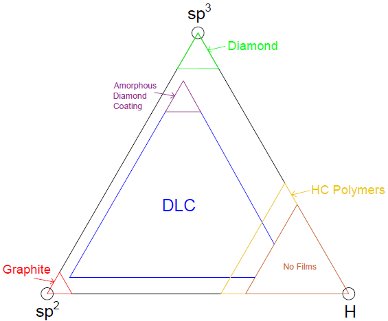
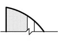
Diamond, the hardest known material on earth, obtains its strength from the structure of carbon molecules. Graphite, a relatively brittle material, can have the same chemical formula as diamond, but is a completely different material; while Graphite has a sp2 bonded hexagonal structure, diamond has a sp3 bonded cubic structure. The cubic structure is harder than the hexagonal structure as more single bonds can be formed to interweave the carbon into a stronger network of molecules.
Amorphous Diamond Coating
Amorphous Diamond is transferred onto carbide tools through a process called physical vapor deposition (PVD). This process spreads a mono-layer of DLC coating about 0.5 – 2.5 microns thick onto any given tool by evaporating a source material and allowing it to condense onto that tool over the course of a few hours.
Chemical Vapor Deposition (CVD)
Chemical Vapor Deposition (CVD) is a coating process used to grow multiple layers of polycrystalline diamond onto carbide tooling. This procedure takes much longer than the standard PVD coating method. During the coating process, hydrogen molecules are dissociated from the carbon molecules deposited onto the tool, leaving a diamond matrix under the right temperature and pressure conditions. Under the wrong conditions, the tool may be simply coated in graphite. 6% cobalt carbide blanks allow for the best adhesion of diamond and a substrate. CVD diamond coated end mills have a typical thickness of coating that is between 8 and 10 microns thick.
Polycrystalline Diamond (PCD)
Polycrystalline Diamond (PCD) is a synthetic diamond, meaning it is grown in a lab and contains mostly cubic structures. Diamond hardness ranges from about 80 GPa up to about 98 GPa. PCD end mills have the same diamond structure as CVD diamond tools but the binding technique is different. The diamond starts in a powdery form that is sintered onto a carbide plate using cobalt as a solvent metal substrate. This is done at an extreme temperature and pressure as the cobalt infiltrates the powder, causing the grains to grow together. This effectively creates a thick diamond wafer, between 010” and .030” in width, with a carbide base. This carbide base is then brazed onto the head an end mill and sharpened.
 How Diamond Coatings Differ
Coating Hardness & Thickness
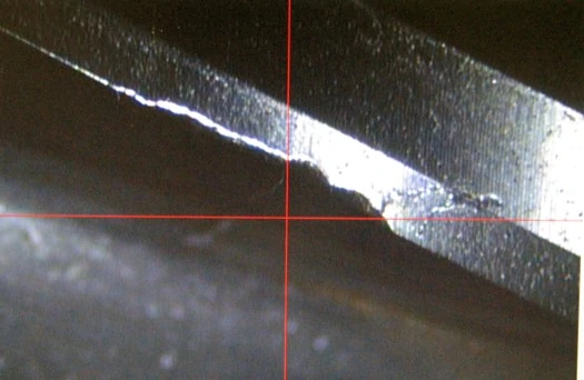
Polycrystalline tools (CVD or sintered) have a much higher hardness, thickness, and max working temperature than Amorphous Diamond oated tools. As mentioned previously, a PCD tool consists of a diamond wafer brazed to a carbide body while a CVD tool is a carbide end mill with a relatively thick layer of polycrystalline diamond grown into it. This grown layer causes the CVD tools to have a rounded cutting edge compared to PCD and Amorphous Diamond coated tools. PCD tools have the thickest diamond layer that is ground to a sharp edge for maximum performance and tool life. The difference between PCD tools and CVD coated tools lies in the thickness of this coat and the sharpness of the cutting edge. Amorphous Diamond tools maintain a sharper edge than CVD coated tools because of their thin coating.
Flute Styles
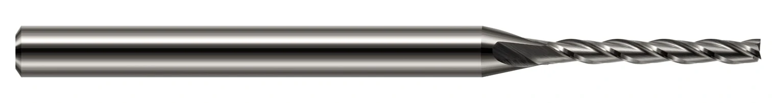
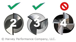
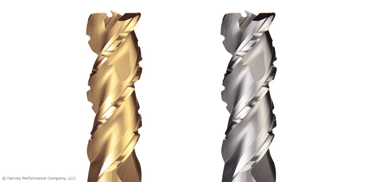
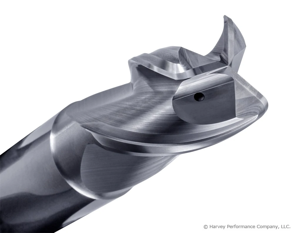
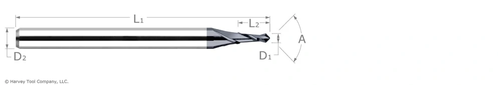
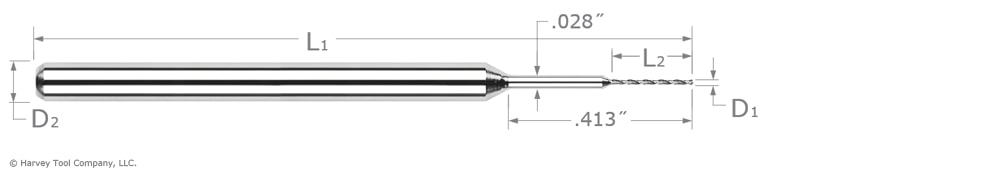
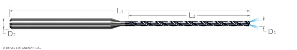
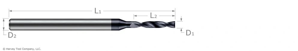
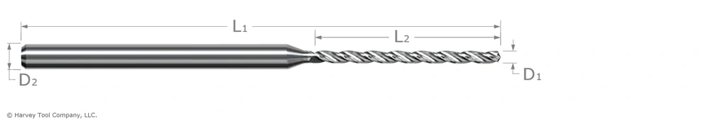
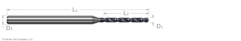
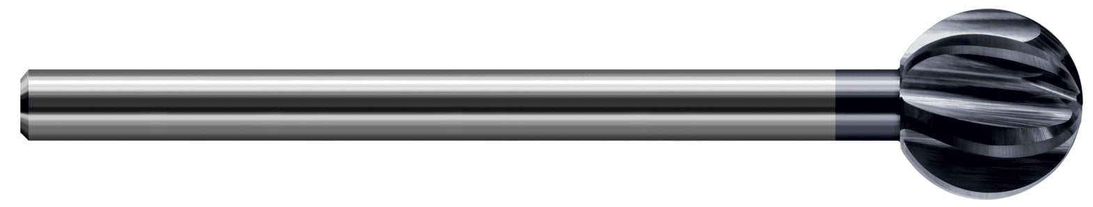
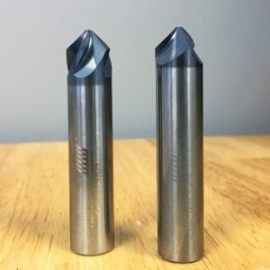
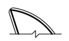
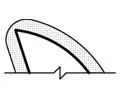
Harvey Tool’s line of PCD end mills are all straight fluted, CVD coated tools are all helically fluted, and Amorphous Diamond tools are offered in a variety of options. The contrast between straight fluted and helically fluted can be seen in the images below, PCD (top) and CVD (bottom). Electrical discharge machining, grinding or erosion are used cut the PCD wafer to the specifications. The size of this wafer limits the range of diameters that can be achieved during manufacturing. In most situations a helically fluted tool would be preferred over a straight fluted tool but with true diamond tooling that is not the case. The materials that PCD tools and CVD coated tools are typically used to cut produce a powdery chip that does not require the same evacuation that a metallic or plastic chip necessitates.
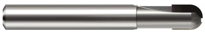
PCD Ball End Mill
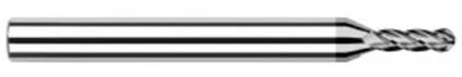
CVD Ball End Mill
Proper Uses
CVD tools are ideally suited for abrasive material not requiring a sharp cutting edge – typically materials that produce a powdery chip such as composites and graphite. Amorphous Diamond tools have a broad range of non-ferrous applications spanning from carbon fiber to precious metals but ceramics are typically outside their range as they can be too abrasive and wear away the coating. PCD tools overlap their CVD and DLC coated counterparts as they can be used for any non-ferrous abrasive material.
Cut to the Point
Harvey Tool carries physical vapor deposition diamond-like carbon coated tools, chemical vapor deposition diamond tools and polycrystalline diamond tools. PCD tools are composed of the thickest diamond wafer brazed onto a carbide shank and are ground to a sharp edge. CVD coated tools have the diamond grown into a carbide end mill. Amorphous Diamond coated tools have the DLC coated onto them through the PVD process. For more information on the diamond coating best suited for your operation, contact a Harvey Tool Tech Team Member for immediate help.