Tag Archive for: Chip Evacuation

Work Hardening and When it Should Scare You

What Is Work Hardening

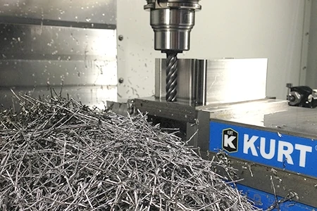
Work hardening is often an unintentional part of the machining process, where the cutting tool generates enough heat in one area to harden the workpiece. It results in plastic deformation which alters the physical structure of the metal being machined. This altered structure affects the machinability of the chosen metal and acts similarly to heat treating. When this occurs the generated speeds and feed requirements will be changed, creating a potential for inefficiency. This makes for a much more difficult machining process and can lead to scrapped parts, broken tools, and serious headaches.

Soften Up Work Hardening With Machining Advisor Pro’s Customizable Speeds and Feeds

What Causes Work Hardening

During machining, the friction between the tool and the workplace generates heat. The heat that is transferred to the workpiece causes the structure of the material to change and in turn harden the material. The degree to which it is hardened depends on the amount of heat being generated in the cutting action and the properties of the material, such as carbon content and other alloying elements. The most influential of these alloying elements include Manganese, Silicon, Nickel, Chromium, and Molybdenum.

While the hardness change will be the highest at the surface of the material, the thermal conductivity of the material will affect how far the hardness changes from the surface of the material.

titanium packed ball bearing

Often times, the thermal properties of a material that makes it appealing for an application are also the main cause of its difficulty to machine. For example, the favorable thermal properties of titanium that allow it to function as a jet turbine are the same properties that cause difficulty in machining it.

Major Problems

Heat Generation

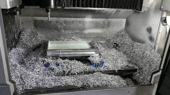
As previously stated, metal work hardening can create some serious problems when machining. The biggest issue is heat generated by the cutting tool and transferring to the workpiece, rather than to the chips. When the heat is transferred to the workpiece, it can cause deformation which will lead to scrapped parts. Stainless Steels and High-Temp Alloys are most prone to work hardening, so extra precaution is needed when machining in these materials.

stringy chips in front of an end mill in the cut

Improper Speeds and Feeds

One other issue that scares a lot of machinists is the chance that a workpiece can harden to the point that it becomes equally as hard as the cutting tool. This is often the case when improper speeds and feeds are used. Incorrect speeds and feeds will cause more rubbing and less cutting, resulting in more heat generation passed to the workpiece. In these situations, machining can become next to impossible, and serious tool wear and eventual tool breakage are inevitable if the tool continues to be fed the same way.

Harvey tool ad for work hardening and speeds and feeds

How To Avoid Work Hardening

There are a few main keys to avoid work hardening: correct speeds and feeds, performing climb milling, selecting appropriate tool coatings, and proper coolant usage. As a general rule of thumb, talking to your tooling manufacturer and using their recommended speeds and feeds is essential for machining success.

Speeds and Feeds

Speeds and feeds become an even bigger priority when you want to avoid heat and tool rubbing, which can both cause serious work hardening. More cutting power and a constant feed rate keeps the tool moving and prevents heat from building up and transferring to the workpiece. The ultimate goal is to get the heat to transfer to the chips, and minimize the heat that is transferred into workpiece and avoiding any deformation of parts. Prior to machining, you should be setting guidelines for each cutting tool to ensure you receive the highest output without compromising on part finish or tool life.
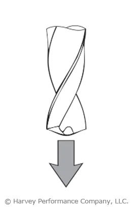
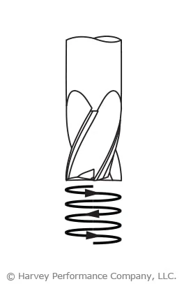
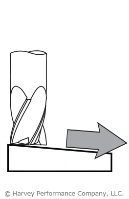
Climb Milling

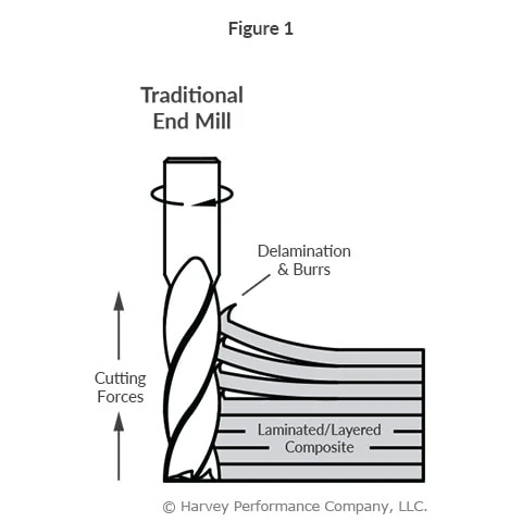
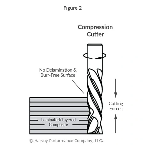
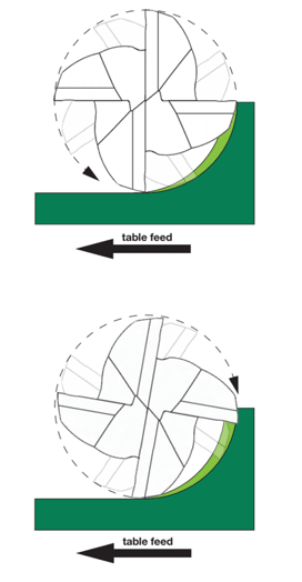
Conventional milling and climb milling are the two ways to perform CNC cutting operations. In climb milling, the cutter rotates with the feed, while in conventional milling the cutter rotates against the feed. However during conventional milling, the chip width starts at zero then increases thus generating heat at the workpiece. This results in work hardening and faster tool wear over time. On the other hand, climb milling begins at maximum chip width and decreases which transfers heat to the chip rather than the tool or workpiece. Climb milling is advantageous because there is less tool rubbing, minimized chance of chip recutting, and enhanced tool life.

drawing that displays conventional milling vs climb milling in cnc cutting operations

Tool Coating

While friction is often the main culprit of heat generation, the appropriate coating for the material may help combat the severity. Many coatings for ferrous materials reduce the amount of friction generated during cutting action. This added lubricity will reduce the friction on the cutting tool and workpiece, therefore transferring the heat generated to the chip, rather than to the workpiece. Tool coatings also create a natural separation between carbide and the workpiece. This minimizes the internal temperature of the carbide as heat is transferred into the chips and workpiece.
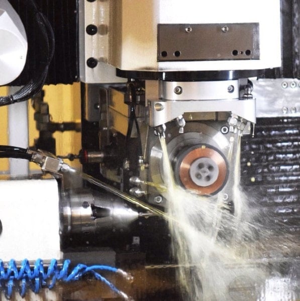
Coolant

Proper coolant usage helps to control the temperature in a cutting operation. Machinists generally choose between using Flooding or High Pressure Coolant options. Flooding the workpiece with coolant may be necessary to maintain the proper temperature, especially when machining in stainless steels and high-temp alloys. This low pressure method creates lubricity to flush chips and avoid chip recutting which commonly damages cutting tools.

high pressure coolant spraying on a part and workpiece during a cnc cutting operation

On the other hand, high pressure coolant delivers enhanced levels of chip evacuation and instant cooling of a part. However, one must be cautious of potentially breaking miniature diameter tooling when using this method due to the higher pressures. Coolant-fed tools can also help to reduce the heat at the contact point, lessening work hardening. While coolant-fed tools are typically a custom modification, saving parts from the scrap heap and using more machine time for the placement part will see the tool pay for itself over time.

Optimize Roughing With Chipbreaker Tooling

What is Chipbreaker Tooling?

Chipbreaker End Mills feature unique notch profiles, creating a serrated cutting edge. These dividers break otherwise long, stringy chips into small, easily-managed swarf that can be cleanly evacuated from the part. But why is a chipbreaker necessary for some jobs, and not others? How does the geometry of this unique tool impact its proper running parameters? In this post, we’ll answer these questions and others to discover the very real benefits of this unique cutting geometry.

up close image of chipbreaker end mill

How Chipbreaker Tooling Works

As a tool rotates and its cutting edge impacts a workpiece, material is sheared off from a part, creating chips. When that cutting process is interrupted, as is the case with breaks in the cutting portion of the tool, chips become smaller in length and are thus easier to evacuate. Because the chipbreakers are offset flute-to-flute, a proper, flat surface finish is achieved as each flute cleans up any excess material left behind from previously passed flutes.

Benefits of Chipbreaker Tooling

Machining Efficiency

When chips are removed from the part, they begin to pile in the machine. For extensive operations, where a great deal of material is hogged out, chip accumulation can very rapidly get in the way of the spindle or part. With larger chips, accumulation occurs much faster, leaving machinists to stop their machine regularly to remove the waste. As any machinist knows, a stopped machine equates to lost money.

small metal chips in cnc machine resulting from the use of a chipbreaker end mill

Prolonged Tool Life

Inefficient chip evacuation can lead to chip recutting, or when the the tool impacts and cuts chips left behind during the machining process. This adds stresses on the tool and accelerates rate of wear on the cutting edge. Chipbreaker tooling creates small chips that are easily evacuated from a part, thus minimizing the risk of recutting.

Accelerated Running Parameters

A Harvey Performance Company Application Engineer recently observed the power of a chipbreaker tool firsthand while visiting a customer’s shop in Minnesota. The customer was roughing a great amount of 4340 Steel. Running at the parameters below, the tool was able to run uninterrupted for two hours!

Helical Part No.33737
Material4340 Steel
ADOC2.545″
RDOC.125″
Speed2,800 RPM
Feed78 IPM
Material Removal Rate24.8 Cubic In/Min


Chipbreaker Product Offering

Chipbreaker Geometry is often utilized in aluminum jobs and with other materials where long, stringy chips are common. Materials that produce a powdery chip, such as graphite, should not be machined with a chipbreaker tool, as chip evacuation would not be a concern. Helical Solutions’ line of chipbreaker tooling includes a 3-flute option for aluminum and non-ferrous materials, and its reduced neck counterpart. Additionally, Helical offers a 4-flute rougher with chipbreaker geometry for high-temp alloys and stainless steels. Harvey Tool’s expansive product offering includes a composite cutting end mill with chipbreaker geometry.

helical solutions 7 flute chipbreaker end mill cutting edges
Helical Solutions 7 Flute Chipbreaker

In Summary

Chipbreaker geometry, or grooves within the cutting face of the tool, break down chips into small, manageable pieces during the machining process. This geometry can boost shop efficiency by minimizing machine downtime to clear large chips from the machining center, improve tool life by minimizing cutting forces exerted on the tool during machining, and allow for more accelerated running parameters.

Why Flute Count Matters

One of the most important considerations when choosing an end mill is determining which flute count is best for the job at hand. Both material and application play an important role in this critical part of the tool selection process. Understanding the effects of flute count on other tool properties, and how a tool will behave in different situations is an essential consideration in the tool selection process. As end mills have become more and more advanced, certain standards have been created for flute counts in certain materials. While there is obvious overlap due to a myriad of factors, proper flute count is critical for machining success and ensuring you are making the most of your end mill and it’s associated MRR.

Machining Advisor Pro (MAP) Takes Flute Count Into Consideration When Helping You Dial In Running Parameters.

Click Here to Get Started.

Tool Geometry Basics

Generally, tools with more flutes have a larger core and smaller flute valleys than tools with fewer flutes.  More flutes with a larger core can provide both benefits and restrictions depending on the application.  Simply put, a larger core is directly proportional to tool strength; the larger the core, the stronger a tool will be.  In turn, a larger core also reduces the flute depth of a tool, restricting the amount of space for chips to exist.  This can cause issues with chip packing in applications requiring heavy material removal.  However, these considerations only lead us part way when making a decision on which tool to use, and when.

3, 5, and 8 flute end mills and their core sizes in relation to flute valleys

Material Considerations

Traditionally, end mills came in either a 2 flute or 4 flute option.  The widely accepted rule of thumb was to use 2 flutes for machining aluminum and non-ferrous materials, and 4 flutes for machining steel and harder alloys.  As aluminum and non-ferrous alloys are typically much softer than steels, a tool’s strength is less of a concern, a tool can be fed faster, and larger material removal rates (MRR) is facilitated by the large flute valleys of 2 flute tools.

Consequently, ferrous materials are typically much harder, and require the strength of a larger core.  Feed rates are slower, resulting in smaller chips, and allowing for the smaller flute valleys of a larger core tool.  This also allows for more flutes to fit on the tool, which in turn increases productivity.

end mill flute count comparisons

Recently, with more advanced machines and toolpaths, higher flute count tools have become the norm in manufacturing.  Non-ferrous tooling has become largely centered on 3 flute tools. This has created a slight advantage over 2 flute tools by increasing productivity while still affording proper chip evacuation. The softness of non-ferrous materials affords a much deeper flute valley. As previously discussed, this allows the tool to be fed much faster than in ferrous materials. Adding an additional flute increases the productivity of the tool, while still affording machinists faster feed rates.

Ferrous tooling has taken a step further and progressed not only to 5 and 6 flutes, but up to 7 flutes and more in some cases.  With a wider range of hardness, sometimes at the very top of the Rockwell hardness scale, many more flutes have allowed longer tool life, less tool wear, stronger tools, and less deflection.  All of this results in more specialized tools for more specific materials. Material specific tooling combines proper flute counts with coatings that aid in lubricity and heat generation to ensure the most effective end mill possible in the material being machined. The end result is higher MRR and increased productivity across the entire range of ferrous materials that machinists will work with in their shops.

Running Parameters

Just as material considerations will have an impact on the tool you choose, operation type and depth of cut requirements may also have a big impact on the ideal number of flutes for your application.  In roughing applications, lower flute counts may be desirable to evacuate large amounts of chips faster with larger flute valleys.  That said, there is a balance to find, as modern toolpaths such as High Efficiency Milling (HEM) can achieve extreme MRR with a very small step over, and a higher number of flutes.  In a more traditional sense, higher flute counts are great for finishing operations where very small amounts of material are being removed, and greater finish can be achieved with more flutes, not worrying as much about chip evacuation as that phase has already been accomplished during roughing.

helical end mill with lines showcasing the flute valleys

Flute count plays a big role in speeds and feeds calculation as well.  One common rule of thumb is “more flutes, more feed,” but this can be a very detrimental misconception.  Although true in some cases, this is not an infinitely scalable principle.  As stated previously, increasing the number of flutes on a tool limits the size that the flute valleys can be.  While adding a 5th flute to a 4 flute tool theoretically gives you 25% more material removal per revolution with an appropriately increased feed rate, feeding the tool that much faster may overload the tool.  The 25% increase in material removal is more likely closer to 10-15%, given the tool is exactly the same in all other specifications.  Higher flute count tools may require speeds and feeds to be backed off so much in some cases, that a lower flute count may be even more efficient.  Finding the right balance is key in modern milling practices. Consulting a tooling manufacturer’s speeds and feeds will be the perfect starting point, and then machinists can make changes as they see fit to properly accomplish the job at hand.

In all, the importance of flute count identification is critical to continued success at the spindle. Different materials have different strength requirements as well as variability in how much material can be appropriately removed per tooth.

How to Avoid Composite Delamination With Compression Cutters

Composites are a group of materials made up of at least two unique constituents that, when combined, produce mechanical and physical properties favorable for a wide array of applications. These materials usually contain a binding ingredient, known as a matrix, filled with particles or fibers called reinforcements. Composites have become increasingly popular in the Aerospace, Automotive, and Sporting Goods industries because they can combine the strength of metal, the light weight of plastic, and the rigidity of ceramics.

Unfortunately, composite materials present some unique challenges to machinists. Many composites are very abrasive and can severely reduce tool life, while others can melt and burn if heat generation is not properly controlled. Even if these potential problems are avoided, the wrong tool can leave the part with other quality issues, including delamination.

While composites such as G10 and FR4 are considered “fibrous”, composites can also be “layered,” such as laminated sheets of PEEK and aluminum. Layered composites are vulnerable to delamination, when the layers of the material are separated by a tool’s cutting forces. This yields less structurally sound parts, defeating the purpose of the combined material properties in the first place. In many cases, a single delaminated hole can result in a scrapped part.

Using Compression Cutter End Mills in Composite Materials

Composite materials are generally machined with standard metal cutting end mills, which generate exclusively up or down cutting forces, depending on if they have right or left hand flute geometry. These uni-directional forces cause delamination (Figure 1).

infographic of delamination with traditional end mill due to upward cutting forces

Conversely, compression cutters are designed with both up and down-cut flutes. The top portion of the length of cut, closest to the shank, has a left hand spiral, forcing chips down. The bottom portion of the length of cut, closest to the end, has a right hand spiral, forcing chips up. When cutting, the opposing flute directions generate counteracting up-cut and down-cut forces. The opposing cutting forces stabilize the material removal, which compresses the composite layers, combatting delamination on the top and bottom of a workpiece (Figure 2).

infographic of no delamination due to even cutting forces with compression cutter end mill

Since compression cutters do not pull up or press down on a workpiece, they leave an excellent finish on layered composites and lightweight materials like plywood. It is important to note, however, that compression cutters are suited specifically to profiling, as the benefits of the up and down-cut geometry are not utilized in slotting or plunging operations.

Something as simple as choosing a tool suited to a specific composite material can have significant effects on the quality of the final part. Consider utilizing tools optimized for different composites and operations or learn how to select the right drill for composite holemaking.

Applying HEM to Micromachining

The following is just one of several blog posts relevant to High Efficiency Milling and Micromachining. To achieve a full understanding of this popular machining method, view any of the additional HEM posts below!

Introduction to High Efficiency Milling I High Speed Machining vs. HEM I How to Combat Chip Thinning I Diving into Depth of Cut I How to Avoid 4 Major Types of Tool Wear I Intro to Trochoidal Milling


Benefits of Using HEM with Miniature Tooling

High Efficiency Milling (HEM) is a technique for roughing that utilizes a lower Radial Depth of Cut (RDOC), and a higher Axial Depth of Cut (ADOC). This delays the rate of tool wear, reducing the chance of failure and prolonging tool life while boosting productivity and Material Removal Rates (MRR). Because this machining method boosts MRR, miniature tooling (<.125”) and micromachining is commonly overlooked for HEM operations. Further, many shops also do not have the high RPM capabilities necessary to see the benefits of HEM for miniature tooling. However, if used properly, miniature tooling can produce the same benefits of HEM that larger diameter tooling can.

Benefits of HEM:

  • Extended tool life and performance.
  • Faster cycle times.
  • Overall cost savings

Preventing Common Challenges in Micromachining

Utilizing miniature tooling for HEM, while beneficial if performed correctly, presents challenges that all machinists must be mindful of. Knowing what to keep an eye out for is a pivotal first step to success.

small harvey tool end mill for micromachining on a penny showing size

Tool Fragility & Breakage with Miniature Tooling

Breakage is one of the main challenges associated with utilizing high efficiency micromachining with miniature tools due to the fragility of the tool. Spindle runout and vibration, tool deflection, material inconsistencies, and uneven loading are just some of the problems which can lead to a broken tool. To prevent this, more attention must be paid to the machine setup and material to ensure the tools have the highest chance of success.

As a general rule, HEM should not be considered when using tools with cutting diameters less than .031”. While possible, HEM may still be prohibitively challenging or risky at diameters below .062”, and your application and machine must be considered carefully.

Techniques to Prevent Tool Failure:

Managing Excessive Heat & Thermal Shock in Micromachining

Due to the small nature of miniature tooling and the high running speeds they require, heat generation can quickly become an issue. When heat is not controlled, the workpiece and tooling may experience thermal cracking, melting, burning, built up edge, or warping.

To combat high heat, coolant is often used to decrease the surface temperature of the material as well as aid in chip evacuation and lubricity. However, care must be taken to ensure that using coolant doesn’t cool the material too quickly or unevenly. If an improper coolant method is used, thermal shock can occur. Thermal shock happens when a material expands unevenly, creating micro fractures that propagate throughout the material and can crack, warp, or change the physical properties of the material.

end mill in the cut with external coolant being applied

Techniques to Prevent Heat & Thermal Shock:

Key Takeaways

If performed properly, miniature tooling micromachining (<.125”) can reap the same benefits of HEM that larger diameter tooling can: reduced tool wear, accelerated part production rates, and greater machining accuracy. However, more care must be taken to monitor the machining process and to prevent tool fragility, excessive heat, and thermal shock.

Check out this example of HEM toolpaths (trochoidal milling) being run with a 3/16″ Harvey Tool End Mill in aluminum.

Tackling Titanium: A Guide to Machining Titanium and Its Alloys

In today’s manufacturing industry, titanium and its alloys have become staples in aerospace, medical, automotive, and firearm applications. This popular metal is resistant to rust and chemicals, is recyclable, and is extremely strong for its weight. However, there are several challenges that must be considered when machining titanium and selecting the appropriate tools and parameters for the job.

Titanium Varieties

Titanium is available in many varieties, including nearly 40 ASTM grades, as well as several additional alloys. Grades 1 through 4 are considered commercially pure titanium with varying requirements on ultimate tensile strength. Grade 5 (Ti6Al4V or Ti 6-4) is the most common combination, alloyed with 6 percent aluminum and 4 percent vanadium. Although titanium and its alloys are often grouped together, there are some key differences between them that must be noted before determining the ideal machining approach.

Titanium 6AL4V chips with helical hvti end mill

Helical Solutions’ HVTI End Mill is a great choice for high efficiency toolpaths in Titanium.

Titanium Concerns

Workholding

Although titanium may have more desirable material properties than your average steel, it also behaves more flexibly, and is often not as rigid as other metals. This requires a secure grip on titanium workpieces, and as rigid a machine setup as is possible. Other considerations include avoiding interrupted cuts, and keeping the tool in motion at all times of contact with the workpiece. Dwelling in a drilled hole or stopping a tool next to a profiled wall will cause the tool to rub – creating excess heat, work-hardening the material, and causing premature tool wear.

Heat Generation

Heat is a formidable enemy, and heat generation must be considered when selecting speeds and feeds. While commercially pure grades of titanium are softer and gummier than most of its alloys, the addition of alloying elements typically raises the hardness of titanium. This increases concerns regarding generated heat and tool wear. Maintaining a larger chipload and avoiding unnecessary rubbing aids with tool performance in the harder titanium alloys, and will minimize the amount of work hardening produced. Choosing a lower RPM, paired with a larger chipload, can provide a significant reduction in temperature when compared to higher speed options. Due to its low conduction properties, keeping temperatures to a minimum will put less stress on the tool and reduce wear. Using high-pressure coolant is also an effective method to reduce heat generation when machining titanium.

mitsubishi evo camshaft cutters machine from titanium with helical solutions end mill

These camshaft covers were custom made in titanium for Mitsubishi Evos.
Photo courtesy of @RebootEng (Instagram)

Galling and Built-Up Edge

The next hurdle to consider is that titanium has a strong tendency to adhere to a cutting tool, creating built up edge. This is a tricky issue which can be reduced by using copious amounts of high pressure coolant aimed directly at the cutting surface. The goal is to remove chips as soon as possible to prevent chip re-cutting, and keep the flutes clean and clear of debris. Galling is a big concern in the commercially pure grades of titanium due to their “gummy” nature. This can be addressed using the strategies mentioned previously, such as continuing feed at all times of workpiece contact, and using plenty of high-pressure coolant.

Titanium Solutions

While the primary concerns when machining titanium and its alloys may shift, the methods for mitigating them remain somewhat constant. The main ideas are to avoid galling, heat generation, work hardening, and workpiece or tool deflection. Use a lot of coolant at high pressure, keep speeds down and feeds up, keep the tool in motion when in contact with the workpiece, and use as rigid of a setup as possible.

In addition, selecting a proper tool coating can help make your job a successful one. With the high heat being generated during titanium machining operations, having a coating that can adequately deal with the temperature is key to maintaining performance through an operation. The proper coating will also help to avoid galling and evacuate chips effectively. Coatings such as Harvey Tool’s Aluminum Titanium Nitride (AlTiN Nano) produce an oxide layer at high temperatures, and will increase lubricity of the tool.

Tooling Solutions

Helical Solutions offers the HVTI-6 line of tooling optimized for High Efficiency Milling (HEM) in Titanium and its alloys. Helical’s HVTI-6 features its Aplus coating which offers added lubricity and high temperature resistance for improved tool life and faster speeds and feeds.

As titanium and its many alloys continue to grow in use across various industries, more machinists will be tasked with cutting this difficult material. However, heat management and appropriate chip evacuation, when paired with the correct coating, will enable a successful run.

machining titanium

Most Common Methods of Tool Entry

Tool entry is pivotal to machining success, as it’s one of the most punishing operations for a cutter. Entering a part in a way that’s not ideal for the tool or operation could lead to a damaged part or exhausted shop resources. Below, we’ll explore the most common part entry methods, as well as tips for how to perform them successfully.


Pre-Drilled Hole

Pre-drilling a hole to full pocket depth (and 5-10% larger than the end mill diameter) is the safest practice of dropping your end mill into a pocket. This method ensures the least amount of end work abuse and premature tool wear. It also facilitates smoother chip evacuation, reducing the risk of chip buildup and potential tool breakage. Machinists often use this technique when working with materials prone to chip welding or built-up edge formation, ensuring consistent machining performance.

tool entry predrill


Helical Interpolation

Helical Interpolation is a very common and safe practice of tool entry with ferrous materials. Employing corner radius end mills during this operation will decrease tool wear and lessen corner breakdown. With this method, use a programmed helix diameter of greater than 110-120% of the cutter diameter. Moreover, helical interpolation offers advantages in achieving precise surface finishes, making it a preferred choice for applications requiring high precision and surface quality, such as aerospace and medical device manufacturing.

helical interpolation


Ramping-In

This type of operation can be very successful, but institutes many different torsional forces the cutter must withstand. A strong core is key for this method, as is room for proper chip evacuation. Using tools with a corner radius, which strengthen its cutting portion, will help. Additionally, ramping-in allows for efficient material removal with reduced axial forces, minimizing workpiece distortion and enhancing dimensional accuracy. Machinists often employ this technique in contouring and pocketing operations, where maintaining part integrity is crucial.

ramping

Suggested Starting Ramp Angles:

Hard/Ferrous Materials: 1°-3°

Soft/Non-Ferrous Materials: 3°-10°

For more information on this popular tool entry method, see Ramping to Success.


Arcing

This method of tool entry is similar to ramping in both method and benefit. However, while ramping enters the part from the top, arcing does so from the side. The end mill follows a curved tool path, or arc, when milling, this gradually increasing the load on the tool as it enters the part. Additionally, the load put on the tool decreases as it exits the part, helping to avoid shock loading and tool breakage. Machinists often utilize this technique in mold making, die sinking, and 3D contouring operations, enhancing productivity and surface finish quality.

arching with end mill


Straight Plunge

This is a common, yet often problematic method of entering a part. A straight plunge into a part can easily lead to tool breakage. If opting for this machining method, however, certain criteria must be met for best chances of machining success. The tool must be center cutting, as end milling incorporates a flat entry point making chip evacuation extremely difficult. Drill bits are intended for straight plunging, however, and should be used for this type of operation.

tool entry


Straight Tool Entry

Straight entry into the part takes a toll on the cutter, as does a straight plunge. Until the cutter is fully engaged, the feed rate upon entry is recommended to be reduced by at least 50% during this operation. Machinists often resort to straight tool entry in simple machining operations with limited tool access or where other entry methods are impractical. However, it’s crucial to monitor tool wear and chip evacuation carefully to prevent chip buildup and potential tool breakage. Adjusting cutting parameters based on material properties and part geometry can further enhance machining efficiency and tool life.

tool entry


Roll-In Tool Entry

Rolling into the cut ensures a cutter to work its way to full engagement and naturally acquire proper chip thickness. The feed rate in this scenario should be reduced by 50%. Roll-in tool entry is particularly advantageous in slotting and profiling operations, where maintaining consistent chip thickness is critical for surface finish quality and dimensional accuracy. Machinists often utilize this technique in high-speed machining applications, maximizing material removal rates while minimizing tool wear and heat generation.

tool entry

Mastering various tool entry techniques is essential for machining success. By understanding and implementing these methods effectively, machinists can optimize performance while prolonging the lifespan of their tools. Continual evaluation of cutting conditions and adaptation of entry strategies based on material properties and part geometry are key to achieving superior machining results.

Dodging Dovetail Headaches: 7 Common Dovetail Mistakes

Cutting With Dovetails

While they are specialty tools, dovetail style cutters have a broad range of applications. Dovetails are typically used to cut O-ring grooves in fluid and pressure devices, industrial slides and detailed undercutting work. Dovetail cutters have a trapezoidal shape—like the shape of a dove’s tail. General purpose dovetails are used to undercut or deburr features in a workpiece. O-ring dovetail cutters are held to specific standards to cut a groove that is wider at the bottom than the top. This trapezoidal groove shape is designed to hold the O-ring and keep it from being displaced.

Check our Harvey Tool’s Comprehensive Selection of Dovetail Cutters that Ship to You Today.

Avoiding Tool Failure

The dovetail cutter’s design makes it fragile, finicky, and highly susceptible to failure. In calculating job specifications, machinists frequently treat dovetail cutters as larger than they really are because of their design, leading to unnecessary tool breakage. They mistake the tool’s larger end diameter as the critical dimension when in fact the smaller neck diameter is more important in making machining calculations.

As the tools are downsized for micro-applications, their unique shape requires special considerations. When machinists understand the true size of the tool, however, they can minimize breakage and optimize cycle time.

Miniature Matters – Micro Dovetailing

As the trend towards miniaturization continues, more dovetailing applications arise along with the need for applying the proper technique when dovetailing microscale parts and features. However, there are several common misunderstandings about the proper use of dovetails, which can lead to increased tool breakage and less-than-optimal cycle times.

There are seven common mistakes made when dovetailing and several strategies for avoiding them:

1. Not Taking Advantage of Drop Holes

Many O-ring applications allow for a drop hole to insert the cutter into the groove. Take advantage of a drop hole if the part design allows it, as it will permit usage of the largest, most rigid tool possible, minimizing the chance of breakage (Figure 1).

infographic examining drop hole allowance parameters with dovetails
Figure 1. These pictured tools are designed to mill a groove for a Parker Hannifin O-ring groove No. AS568A-102 (left). These O-rings have cross sections of 0.103″. There is a large variation in the tools’ neck diameters. The tool at right, with a neck diameter of 0.024″, is for applications without a drop hole, while the other tool, with a neck diameter of 0.088″, is for drop-hole applications. The drop-hole allowance allows application of the more rigid tool.

2. Misunderstanding a Dovetail’s True Neck Diameter.

The dovetail’s profile includes a small neck diameter behind a larger end-cutting diameter. In addition, the flute runs through the neck, further reducing the tool’s core diameter. (In the example shown in Figure 2, this factor produces a core diameter of just 0.014″.) The net result is that an otherwise larger tool becomes more of a microtool. The torque generated by the larger diameter is, in effect, multiplied as it moves to the narrower neck diameter. You must remember that excess stress may be placed on the tool, leading to breakage. Furthermore, as the included angle of a dovetail increases, the neck diameter and core diameter are further reduced. O-ring dovetail cutters have an included angle of 48°. Another common included angle for general purpose dovetails is 90°. Figure 3 illustrates how two 0.100″-dia. dovetail tools have different neck diameters of 0.070″ vs. 0.034″ and different included angles of 48° vs. 90°.

nondrop-hole dovetail cutters
Figure 2. The dovetail tool pictured is the nondrop-hole example from Figure 1. The cross section illustrates the relationship between the end diameter of the tool (0.083″) and the significantly smaller core diameter (0.014″). Understanding this relationship and the effect of torque on a small core diameter is critical to developing appropriate dovetailing operating parameters.
dovetail cutters with different neck diameters
Figure 3: These dovetail tools have the same end diameter but different neck diameters (0.070″ vs. 0.034″) and different included angles (48° vs. 90°).

3. Calculating Speeds and Feeds from the Wrong Diameter.

Machinists frequently use the wrong tool diameter to calculate feed rates for dovetail cutters, increasing breakage. In micromachining applications where the margin for error is significantly reduced, calculating the feed on the wrong diameter can cause instantaneous tool failure. Due to the angular slope of a dovetail cutter’s profile, the tool has a variable diameter. While the larger end diameter is used for speed calculations, the smaller neck diameter should be used for feed calculations. This yields a smaller chip load per tooth. For example, a 0.083″-dia. tool cutting aluminum might have a chip load of approximately 0.00065 IPT, while a 0.024″-dia. mill cutting the same material might have a 0.0002-ipt chip load. This means the smaller tool has a chip load three times smaller than the larger tool, which requires a significantly different feed calculation.

4. Errors in Considering Depth of Cut.

In micromachining applications, machinists must choose a depth of cut (DOC) that does not exceed the limits of the fragile tool. Typically, a square end mill roughs a slot and the dovetail cutter then removes the remaining triangular-shaped portion. As the dovetail is stepped over with each subsequent radial cut, the cutter’s engagement increases with each pass. A standard end mill allows for multiple passes by varying the axial DOC. However, a dovetail cutter has a fixed axial DOC, which allows changes to be made only to the radial DOC. Therefore, the size of each successive step-over must decrease to maintain a more consistent tool load and avoid tool breakage (Figure 4).

microdovetailing with dovetail cutter
Figure 4: In microdovetailing operations, increased contact requires diminishing stepover to maintain constant tool load.

5. Failing to Climb Mill.

Although conventional milling has the benefit of gradually loading the tool, in low-chip load applications (as dictated by a dovetail cutter’s small neck diameter) the tool has a tendency to rub or push the workpiece as it enters the cut, creating chatter, deflection and premature cutting edge failure. The dovetail has a long cutting surface and tooth pressure becomes increasingly critical with each pass. Due to the low chip loads encountered in micromachining, this approach is even more critical to avoid rubbing. Although climb milling loads the tool faster than conventional milling, it allows the tool to cut more freely, providing less deflection, finer finish and longer cutting-edge life. As a result, climb milling is recommended when dovetailing.

6. Improper Chip Flushing.

Because dovetail cuts are typically made in a semi-enclosed profile, it is critical to flush chips from the cavity. In micro-dovetailing applications, chip packing and recutting due to poorly evacuated chips from a semi-enclosed profile will dull the cutter and lead to premature tool failure. In addition to cooling and lubricating, a high-pressure coolant effectively evacuates chips. However, excessive coolant pressure placed directly on the tool can cause tool vibration and deflection and even break a microtool before it touches the workpiece. Take care to provide adequate pressure to remove chips without putting undue pressure on the tool itself. Specific coolant pressure settings will depend upon the size of the groove, the tool size and the workpiece material. Also, a coolant nozzle on either side of the cutter cleans out the groove ahead of and behind the cutter. An air blast or vacuum hose could also effectively remove chips.

7. Giving the Job Away.

As discussed in item number 3, lower chip loads result in significantly lower material-removal rates, which ultimately increase cycle time. In the previous example, the chip load was three times smaller, which would increase cycle time by the same amount. Cycle time must be factored into your quote to ensure a profitable margin on the job. In addition to the important micro-dovetailing considerations discussed here, don’t forget to apply the basics critical to all tools. These include keeping runout low, using tools with application-specific coatings and ensuring setups are rigid. All of these considerations become more important in micro-applications because as tools get smaller, they become increasingly fragile, decreasing the margin of error. Understanding a dovetail cutter’s profile and calculating job specifications accordingly is critical to a successful operation. Doing so will help you reach your ultimate goal: bidding the job properly and optimizing cycle time without unnecessary breakage.

This article was written by Peter P. Jenkins of Harvey Tool Company, and it originally appeared in MicroManufacturing Magazine.

Selecting the Right Plastic Cutting End Mill

Many challenges can arise when machining different types of plastics. In the ever changing plastics industry, considerations for workholding, the melting point of your material, and any burrs that may potentially be created on the piece need to be examined prior to selecting a tool. Choosing the correct tool for your job and material is pivotal to avoid wasting time and money. Harvey Tool offers One, Two, and Three Flute Plastic Cutting End Mills with Upcut and Downcut Geometries. The following guide is intended to aid in the tool selection process to avoid common plastic cutting mistakes.

three Harvey tool plastic cutting end mills

Choose Workholding Method

When it comes to workholding, not all plastic parts can be secured by clamps or vices. Depending on the material’s properties, these workholding options may damage or deform the part. To circumnavigate this, vacuum tables or other weaker holding forces, such as double sided tape, are frequently used. Since these workholdings do not secure the part as tightly, lifting can become a problem if the wrong tool is used.

Downcut Plastic Cutting End Mills — tools with a left hand spiral, right hand cut — have downward axial forces that push chips down, preventing lifting and delamination. If an Upcut Plastic Cutting End Mill is required, then a tool with minimal upward forces should be chosen. The slower the cutter’s helix, the less upward forces it will generate on the workpiece.

Chart of workholding parameters and their preferred selection to upcut or downcut as a result

Determine Heat Tolerance

The amount of heat generated should always be considered prior to any machining processes, but this is especially the case while working in plastics. While machining plastics, heat must be removed from the contact area between the tool and the workpiece quickly and efficiently to avoid melting and chip welding.

If your plastic has a low melting point, a Single Flute Plastic Cutting End Mill is a good option. This tool has a larger flute valley than its two flute counterpart which allows for bigger chips. With a larger chip, more heat can be transferred away from the material without it melting.

For plastics with a higher heat tolerance, a Two or Three Flute Plastic Cutting End Mill can be utilized. Because it has more cutting edges and allows for higher removal rates, its tool life is extended.

Chart of end mill flute count and their respective workpiece heat tolerance levels

Consider Finish Quality & Deburring

The polymer arrangement in plastics can cause many burrs if the proper tool is not selected. Parts that require hand-deburring offline after the machining process can drain shop resources. A sharp cutting edge is needed to ensure that the plastic is sheared cleanly, reducing the occurrence of burrs. Three Flute Plastic Cutting End Mills can reduce or eliminate the need to hand-deburr a part. These tools employ an improved cutting action and rigidity due to the higher flute count. Their specialized end geometry reduces the circular end marks that are left behind from traditional metal cutting end mills, leaving a cleaner finish with minimal burrs.

Shop Harvey Tool Plastic Cutting End Mills Today

Flute Count Case Study

2 FLUTE PLASTIC CUTTER: A facing operation was performed in acrylic with a standard 2 Flute Plastic Cutting End Mill. The high rake, high relief design of the 2 flute tool increased chip removal rate, but also left distinct swirling patterns on the top of the workpiece.

3 FLUTE PLASTIC FINISHER: A facing operation was performed on a separate acrylic piece with a specialized 3 Flute Plastic Finisher End Mill. The specialized cutting end left minimal swirling marks and resulted in a smoother finish.

Image of facing operation patterns from a standard 2 flute plastic cutter beside another image from a specialized 3 flute plastic finisher

Identifying the potential problems of cutting a specific plastic is an important first step when choosing an appropriate plastic cutter. Deciding on the right tool can mean the difference between an excellent final product and a scrapped job. Harvey Tool’s team of technical engineers is available to help answer any questions you might have about selecting the appropriate Plastic Cutting End Mill.

Chart of plastic cutting end mills vs metal cutting end mills that compares values on their features

How to Tackle Deep Cavity Milling the Right Way

Deep cavity milling is a common yet demanding milling operation. In this style, the tool has a large amount of overhang – or how far a cutting tool is sticking out from its tool holder. The most common challenges of deep cavity milling include tool deflection, chip evacuation, and tool reach.

Three Harvey tool extended reach tool holders in 3, 5, and 6 inch lengths

Avoid Tool Deflection

Excess overhang is the leading cause of tool deflection, due to a lack of rigidity. Besides immediate tool breakage and potential part scrapping, excessive overhang can compromise dimensional accuracy and prevent a desirable finish.

Tool deflection causes wall taper to occur (Figure 1), resulting in unintended dimensions and, most likely, an unusable part. By using the largest possible diameter, necked tooling, and progressively stepping down with lighter Axial Depths Of Cut (ADOC), wall taper is greatly reduced (Figure 2).

Infographic showing result of tool deflection and excess overhang on a part's finish
Infographic showing progressive step drilling procedures and depths of cut with varied length of tools

Achieve Optimal Finish

Although increasing your step-downs and decreasing your ADOC are ideal for roughing in deep cavities, this process oftentimes leaves witness marks at each step down. In order to achieve a quality finish, Long Reach, Long Flute Finishing End Mills (coupled with a light Radial Depth of Cut) are required (Figure 3).

Inforgraphic showing Deep Cavity Milling and witness marks from multiple step downs

Mill to the Required Depth

Avoiding tool deflection and achieving an acceptable finish are challenges that need to be acknowledged, but what if you can’t even reach your required depth? Inability to reach the required depth can be a result of the wrong tool holder or simply a problem of not having access to long enough tooling.

Fortunately, your tool holder’s effective reach can be easily increased with Harvey Tool’s Extended Reach Tool Holder, which allows you to reach up to 6 inches deeper.

Confidently Machine Deeper With Harvey Tool’s Extended Reach Tool Holders

Evacuate Chips Effectively

Many machining operations are challenged by chip evacuation, but none more so than Deep Cavity Milling. With a deep cavity, chips face more obstruction, making it more difficult to evacuate them. This frequently results in greater tool wear from chip cutting and halted production from clogged flute valleys.

High pressure coolant, especially through the spindle, aids in the chip evacuation process. However, air coolant is a better option if heat and lubricity are not concerns, since coolant-chip mixtures can form a “slurry” at the bottom of deep cavities (Figure 4). When machining hardened alloys, where smaller, powder-like chips are created, slurry’s are a commonality
that must be avoided.

Deep Cavity Milling image showing result of failed chip evacuation when milling