Tag Archive for: Cutting Tools

5 Questions to Ask Before Selecting an End Mill

Few steps in the machining process are as important as proper end mill selection. Complicating the process is the fact that each individual tool has its own unique geometries, each pivotal to the eventual outcome of your part. We recommend asking yourself 5 key questions before beginning the tool selection process. In doing so, you can ensure that you are doing your due diligence in selecting the best tool for your application. Taking the extra time to ensure that you’re selecting the optimal tool will reduce cycle time, increase tool life, and produce a higher quality product.

Question 1: What Material Am I Cutting?

Knowing the material you are working with and its properties will help narrow down your end mill selection considerably. Each material has a distinct set of mechanical properties that give it unique characteristics when machining. For instance, plastic materials require a different machining strategy – and different tooling geometries – than steels do. Choosing a tool with geometries tailored towards those unique characteristics will help to improve tool performance and longevity.

Harvey Tool stocks a wide variety of High Performance Miniature End Mills. Its offering includes tooling optimized for hardened steels, exotic alloys, medium alloy steels, free machining steels, aluminum alloys, highly abrasive materials, plastics, and composites. If the tool you’re selecting will only be used in a single material type, opting for a material specific end mill is likely your best bet. These material specific tools provide tailored geometries and coatings best suited to your specific material’s characteristics. But if you’re aiming for machining flexibility across a wide array of materials, Harvey Tool’s miniature end mill section is a great place to start.

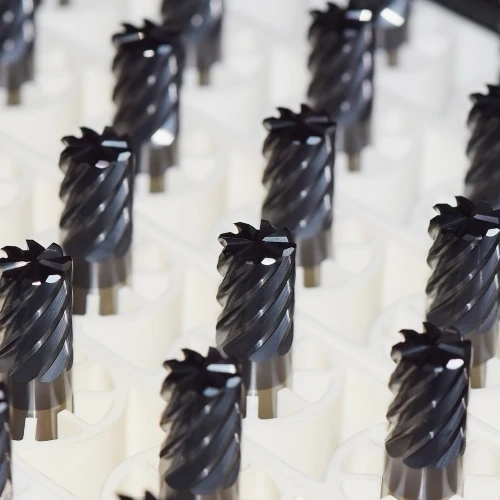
Shop Harvey Tool’s Massive Offering of Fully Stocked Miniature End Mills

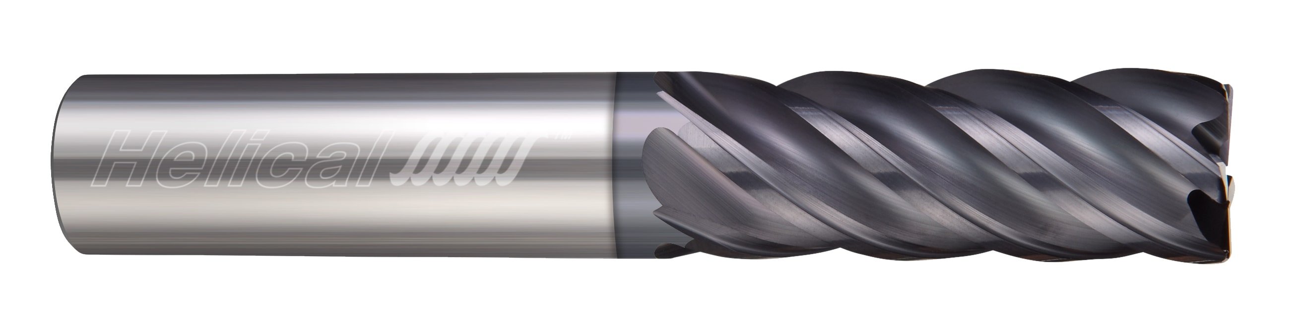
Helical Solutions also provides a diverse product offering tailored to specific materials, including Aluminum Alloys & Non-Ferrous Materials; and Steels, High-Temp Alloys, & Titanium. Each section includes a wide variety of flute counts – from 2 flute end mills to Multi-Flute Finishers, and with many different profiles, coating options, and geometries.

Question 2: Which Operations Will I Be Performing?

An application can require one or many operations. Common machining operations include:

  • Traditional Roughing
  • Slotting
  • Finishing
  • Contouring
  • Plunging
  • High Efficiency Milling

By understanding the operations(s) needed for a job, a machinist will have a better understanding of the tooling that will be needed. For instance, if the job includes traditional roughing and slotting, selecting a Helical Solutions Chipbreaker Rougher to hog out a greater deal of material would be a better choice than a Finisher with many flutes.

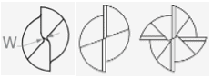
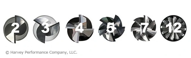
Question 3: How Many Flutes Do I Need?

One of the most significant considerations during end mill selection is determining proper flute count. Both the material and application play an important role in this decision.

Material:

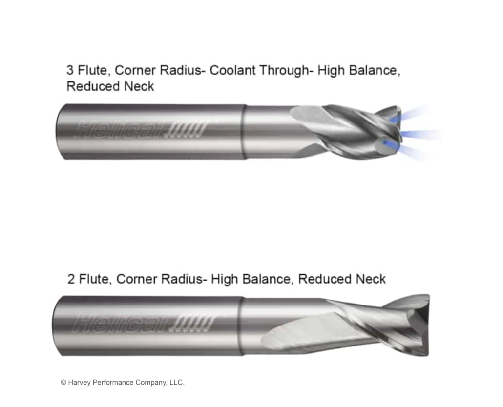
When working in Non-Ferrous Materials, the most common options are the 2 or 3-flute tools. Traditionally, the 2-flute option has been the desired choice because it allows for excellent chip clearance. However, the 3-flute option has proven success in finishing and High Efficiency Milling applications, because the higher flute count will have more contact points with the material.

Ferrous Materials can be machined using anywhere from 3 to 14-flutes, depending on the operation being performed.

Application:

Traditional Roughing: When roughing, a large amount of material must pass through the tool’s flute valleys en route to being evacuated. Because of this, a low number of flutes – and larger flute valleys – are recommend. Tools with 3, 4, or 5 flutes are commonly used for traditional roughing.

Slotting: A 4-flute option is the best choice, as the lower flute count results in larger flute valleys and more efficient chip evacuation.

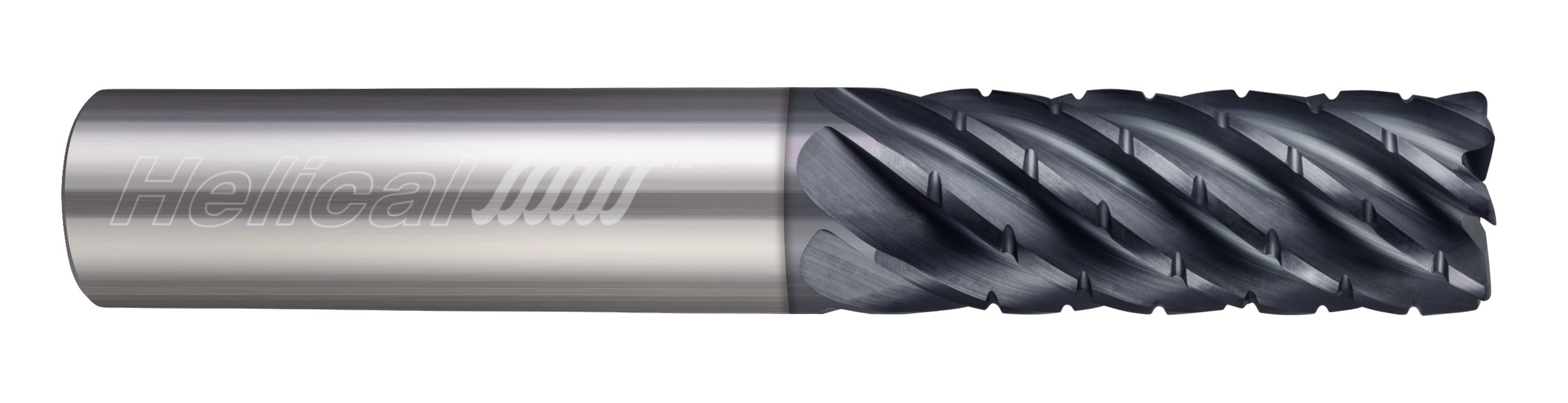
Finishing: When finishing in a ferrous material, a high flute count is recommended for best results. Finishing End Mills include anywhere from 5-to-14 flutes. The proper tool depends on how much material remains to be removed from a part.

High Efficiency Milling: HEM is a style of roughing that can be very effective and result in significant time savings for machine shops. When machining an HEM toolpath, opt for 5 to 7-flutes.

graphic showcasing the tool face of end mills from 2 to 12 flutes

Question 4: What Specific Tool Dimensions are Needed?

After specifying the material you are working in, the operation(s) that are going to be performed, and the number of flutes required, the next step is making sure that your end mill selection has the correct dimensions for the job. Examples of key considerations include cutter diameter, length of cut, reach, and profile.

Cutter Diameter

The cutter diameter is the dimension that will define the width of a slot, formed by the cutting edges of the tool as it rotates. Selecting a cutter diameter that is the wrong size – either too large or small – can lead to the job not being completed successfully or a final part not being to specifications.  For example, smaller cutter diameters offer more clearance within tight pockets, while larger tools provide increased rigidity in high volume jobs.

Length of Cut & Reach

The length of cut needed for any end mill should be dictated by the longest contact length during an operation. This should be only as long as needed, and no longer. Selecting the shortest tool possible will result in minimized overhang, a more rigid setup, and reduced chatter. As a rule of thumb, if an application calls for cutting at a depth greater than 5x the tool diameter, it may be optimal to explore necked reach options as a substitute to a long length of cut.
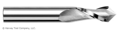
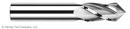
Tool Profile

The most common profile styles for end mills are square, corner radius, and ball. The square profile on an end mill has flutes with sharp corners that are squared off at 90°. A corner radius profile replaces the fragile sharp corner with a radius, adding strength and helping to prevent chipping while prolonging tool life. Finally, a ball profile features flutes with no flat bottom, and is rounded off at the end creating a “ball nose” at the tip of the tool. This is the strongest end mill style.  A fully rounded cutting edge has no corner, removing the mostly likely failure point from the tool, contrary to a sharp edge on a square profile end mill. An end mill profile is often chosen by part requirements, such as square corners within a pocket, requiring a square end mill.  When possible, opt for a tool with the largest corner radius allowable by your part requirements. We recommend a corner radii whenever your application allows for it. If square corners are absolutely required, consider roughing with a corner radius tool and finishing with the square profile tool.

end mill graphic with dimension callouts

Question 5: Should I Use a Coated Tool?

When used in the correct application, a coated tool will help to boost performance by providing the following benefits:

  • More Aggressive Running Parameters
  • Prolonged Tool life
  • Improved Chip Evacuation

Harvey Tool and Helical Solutions offer many different coatings, each with their own set of benefits. Coatings for ferrous materials, such as AlTiN Nano or TPlus, typically have a high max working temperature, making them suitable for materials with a low thermal conductivity. Coatings for non-ferrous applications, such as TiB2 or ZPlus, have a low coefficient of friction, allowing for easier machining operations. Other coatings, such as Amorphous Diamond or CVD Diamond Coatings, are best used in abrasive materials because of their high hardness rating.

multiple end mills after being coated, zoomed in on cutting faces

Ready to Decide on an End Mill

There are many factors that should be considered while looking for the optimal tooling for the job, but asking the aforementioned five key question during the process will help you to make the right decision. As always, The Harvey Performance Company Technical Service Department is always available to provide recommendations and walk you through the tool selection process, if need be.

Harvey Tool Technical Support: 800-645-5609

Helical Solutions Technical Support: 866-543-5422

Experience the Benefits of Staggered Tooth Keyseats

Keyseat Cutters, also known as Woodruff Cutters, Keyway Cutters, and T-Slot Cutters, are commonly used in machine shops. Many machinists opt to use this tool to put a slot on the side of a part in an efficient manner, rather than rotating the workpiece and using a traditional end mill. A Staggered Tooth Keyseat Cutter has alternating right-hand and left hand shear flutes and is right-hand cut, whereas a traditional keyseat cutter has all straight flutes and is right-hand cut. Simply, the unique geometry of a Staggered Tooth Keyseat Cutter gives the tool its own set of advantages including the ability to index within the slot, increase feed rates, and achieve better part finish.

face of a staggered tooth keyseat cutter

Three Key Benefits

Indexing

The alternating right-and-left-hand flutes of a Harvey Tool Staggered Tooth Keyseat Cutters are relieved on both sides of its head, meaning that it allows for both end cutting and back cutting. This adds to the versatility of the staggered tooth keyseat cutter, where one singular tool can be indexed axially within a slot to expand the slot to a specific uncommon dimension. This can save space in a machinist’s magazine and reduce machine time by eliminating the need to swap to a new tool.

Increased Feed Rates

Due to the unique geometry of a Staggered Tooth Keyseat Cutter, chips evacuate efficiently and at a faster rate than that of a Straight Flute Keyseat Cutter. The unique flutes of Staggered Tooth Keyseat Cutters are a combination of right-and-left-hand shear flutes, but both types are right-hand cutting. This results in the tool’s teeth alternating between upcut and downcut. Chip packing and chip recutting is less of a concern with running this tool, and results in increased chip loads compared to that of a standard keyseat with the same number of flutes. Because of this, the tool can account for chiploads of about 10% higher than the norm, resulting in heightened feed rates and shorter cycle times overall.

Better Part Finish

Staggered Tooth Keyseat Cutters have “teeth”, or flutes, that are ground at an angle creating a shear flute geometry. This geometry minimizes chip recutting, chip dragging and reduces the force needed to cut into the material. Chip recutting and dragging are minimized because chips are evacuated out of the top and bottom of the head on the side of the cutter that is not engaged in the material. Shear flutes also reduce vibrations that can lead to chatter and poor finish. By minimizing cutting forces, vibration, and chatter, a machinist can expect a better part finish.

staggered tooth keyseat cutter working in a cnc machine

Image courtesy of @edc_machining

Staggered Tooth Keyseat Cutter Diverse Product Offering

On top of the higher performance one will experience when using the Stagger Tooth Keyseats, there are also multiple options available with various combinations to suit multiple machining needs. This style is offered in a square, square reduced shank and corner radius profile which helps if a fillet or sharp corner is needed. The square and corner radius tools are offered in diameters ranging from 1/8” to 5/8”, and the square reduced shank tool is offered in diameteres ranging from 3/4″ to 1-1/2″. The increased diameter comes with an increase of radial depth of cut, allowing deeper slots to be achievable. Within the most popular cutter diameters, ¼”, 3/8”, and ½” there are also deep slotting options with even greater radial depth of cuts for increased slot depths. On top of the diameters and radii, there are also multiple cutter widths to choose from to create different slots in one go. Finally, an uncoated and AlTiN coatings are available to further increase tool life and performance depending on the material that is being cut.

Opt for a Smoother Operation

A Staggered Tooth Keyseat Cutter adds versatility to a tool magazine. It can be indexed axially to expand slots to make multiple widths, allowing machinists to progress operations in a more efficient manner where tool changes are not required. Further, this tool will help to reduce harmonics and chatter, as well as minimize recutting. This works to create a smoother operation with less force on the cutter, resulting in a better finish compared to a Standard Keyseat Cutter.

For more information on Harvey Tool Staggered Tooth Keyseat Cutters and its applications, visit Harvey Tool’s Keyseat Cutter page.

Get to Know Machining Advisor Pro

Machining Advisor Pro (MAP) is a tool to quickly, seamlessly, and accurately deliver recommended running parameters to machinists using Helical Solutions end mills. This download-free and mobile-friendly application takes into account a user’s machine, tool path, set-up, and material to offer tailored, specific speeds and feed parameters to the tools they are using.

How to Begin With Machining Advisor Pro

This section will provide a detailed breakdown of Machining Advisor Pro, moving along step-by-step throughout the entire process of determining your tailored running parameters.

Register Quickly on Desktop or Mobile

To begin with Machining Advisor Pro, start by accessing its web page on the Harvey Performance Company website, or use the mobile version by downloading the application from the App Store or Google Play.

Whether you are using Machining Advisor Pro from the web or your mobile device, machinists must first create an account. The registration process will only need to be done once before you will be able to log into Machining Advisor Pro on both the mobile and web applications immediately.

machining advisor pro

Simply Activate Your Account

The final step in the registration process is to activate your account. To do this, simply click the activation link in the email that was sent to the email address used when registering. If you do not see the email in your inbox, we recommend checking your spam folders or company email filters. From here, you’re able to begin using MAP.

Using Machining Advisor Pro

A user’s experience will be different depending on whether they’re using the web or mobile application. For instance, after logging in, users on the web application will view a single page that contains the Tool, Material, Operation, Machine, Parameter, and Recommendation sections.

machining advisor pro

On the mobile application, however, the “Input Specs” section is immediately visible. This is a summary of the Tool, Material, Operation, and Machine sections that allow a user to review and access any section. Return to this screen at any point by clicking on the gear icon in the bottom left of the screen.

machining advisor pro

Identify Your Helical Tool

To get started generating your running parameters, specify the Helical Solutions tool that you are using. This can be done by entering the tool number into the “Tool #” input field (highlighted in red below). As you type the tool number, MAP will filter through Helical’s 4,800-plus tools to begin identifying the specific tool you are looking for.

machining advisor pro

Once the tool is selected, the “Tool Details” section will populate the information that is specific to the chosen tool. This information will include the type of tool chosen, its unit of measure, profile, and other key dimensional attributes.

Select the Material You’re Working In

Once your tool information is imported, the material you’re working in will need to be specified. To access this screen on the mobile application, either swipe your screen to the left or click on the “Material” tab seen at the bottom of the screen. You will move from screen to screen across each step in the mobile application by using the same method.

In this section, there are more than 300 specific material grades and conditions available to users. The first dropdown menu will allow you to specify the material you are working in. Then, you can choose the subgroup of that material that is most applicable to your application. In some cases, you will also need to choose a material condition. For example, you can select from “T4” or “T6” condition for 6061 Aluminum.

Machining Advisor Pro provides optimized feeds and speeds that are specific to your application, so it is important that the condition of your material is selected.

Pick an Operation

The next section of MAP allows the user to define their specific operation. In this section, you will define the tool path strategy that will be used in this application. This can be done by either selecting the tool path from the dropdown menu or clicking on “Tool Path Info” for a visual breakdown and more information on each available toolpath.

Tailor Parameters to Your Machine’s Capabilities

The final section on mobile, and the fourth web section, is the machine section. This is where a user can define the attributes of the machine that you are using. This will include the Max RPM, Max IPM, Spindle, Holder, and work holding security. Running Parameters will adjust based on your responses.

Access Machining Advisor Pro Parameters

Once the Tool, Material, Operation, and Machine sections are populated there will be enough information to generate the initial parameters, speed, and feed. To access these on the mobile app, either swipe left when on the machine tab or tap on the “Output” tab on the bottom menu.

Please note that these are only initial values. Machining Advisor Pro gives you the ability to alter the stick out, axial depth of cut, and radial depth of cut to match the specific application. These changes can either be made by entering the exact numeric value, the % of cutter diameter, or by altering the slider bars. You are now able to lock RDOC or ADOC while adjusting the other depth of cut, allowing for more customization when developing parameters.

machining advisor pro

The parameters section also offers a visual representation of the portion of the tool that will be engaged with the materials as well as the Tool Engagement Angle.

MAP’s Recommendations

At this point, you can now review the recommended feeds and speeds that Machining Advisor Pro suggests based on the information you have input. These optimized running parameters can then be further refined by altering the speed and feed percentages.

machining advisor pro recommendation

Machining Advisor Pro recommendations can be saved by clicking on the PDF button that is found in the recommendation section on both the web and mobile platforms. This will automatically generate a PDF of the recommendations, allowing you to print, email, or share with others.

Machining Advisor Pro Summarized

The final section, exclusive to the mobile application, is the “Summary” section. To access this section, first tap on the checkmark icon in the bottom menu. This will open a section that is similar to the “Input Specs” section, which will give you a summary of the total parameter outputs. If anything needs to change, you can easily jump to each output item by tapping on the section you need to adjust.

machining advisor pro mobile

This is also where you would go to reset the application to clear all of the inputs and start a new setup. On the web version, this button is found in the upper right-hand corner and looks like a “refresh” icon on a web browser.

Contact Us

For the mobile application, we have implemented an in-app messaging service. This was done to give the user a tool to easily communicate any question they have about the application from within the app. It allows the user to not only send messages, but to also include screenshots of what they are seeing! This can be accessed by clicking on the “Contact Us” option in the same hamburger menu that the Logout and Help & Tips are found.

Click this link to sign up today!

B&R Custom Machining- Featured Customer

Featured Image Courtesy of B&R Custom Machining

B&R Custom Machining is a rapidly expanding aerospace machine shop located in Ontario, Canada, focused primarily on aerospace and military/defense manufacturing. Over the past 17 years, B&R has grown from a 5 person shop with a few manual mills and lathes, into one of Canada’s most highly respected manufacturing facilities, with nearly 40 employees and 21 precision CNC machines.

B&R focuses on quality assurance and constant improvement, mastering the intimacies of metal cutting and maintaining the highest levels of quality through their unique shop management philosophies. They seek to consistently execute on clear contracts through accurate delivery, competitive price, and high quality machined components.

We talked with Brad Jantzi, Co-Founder and Technical Manager of B&R Custom Machining, to learn about how he started in the industry, his experience with High Efficiency Milling, what he looks for most in a cutting tool, and more!

B&R Custom machining

Photo Courtesy of: B&R Custom Machining

Can you tell us a little bit about how B&R Custom Machining started, and a little background about yourself and the company?

My brother (Ryan Jantzi, CEO/Co-Founder) and I started working in manufacturing back in 2001, when we were just 20/21 years old. We had 5 employees (including ourselves), a few manual mills and lathes, and we were wrapping our parts in newspaper for shipping. We took over from a preexisting shop and assumed their sales and machines.

We bought our first CNC machine in 2003, and immediately recognized the power of CNC and the opportunities it could open up for us. Now, we have 21 CNC machines, 38 employees, and more requests for work than we can keep up with, which is a good thing for the business. We are constantly expanding our team to elevate the business and take on even more work, and are currently hiring for multiple positions if anyone in Ontario is looking for some challenging and rewarding work!

What kind of CNC machines are you guys working with?

Right now we have a lot of Okuma and Matsuura machines, many of which have 5 axis capabilities, and all of them with high RPM spindles. In fact, our “slowest” machine runs at 15k RPM, with our fastest running at 46k. One of our high production machines is our Matsuura LX160, which has the 46k RPM spindle. We use a ton of Harvey Tool and Helical product on that machine and really get to utilize the RPMs.

B&R Custom Machining

Photo Courtesy of: B&R Custom Machining

What sort of material are you cutting?

We work with Aluminum predominantly, but also with a lot of super alloys like Invar, Kovar, Inconel, Custom 455 Stainless, and lots of Titanium. Some of those super alloys are really tricky stuff to machine. Once we learn about them and study them, we keep a recorded database of information to help us dial in parameters. Our head programmer/part planner keeps track of all that information, and our staff will frequently reference old jobs for new parts.

Sounds like a great system you guys have in place. How did B&R Custom Machining get into aerospace manufacturing?

It is a bit of a funny story actually. Just about 12 years ago we were contacted by someone working at Comdev, which is close to our shop, who was looking to have some parts made. We started a business relationship with him, and made him his parts. He was happy with the work, and so we eventually got involved in his company’s switch division and started to make more and more aerospace parts.

aerospace machining

Photo Courtesy of: B&R Custom Machining

We immediately saw the potential of aerospace manufacturing, and it promoted where we wanted to go with CNC machining, so it was a natural fit. It really was a case of being in the right place at the right time and seizing the moment. If an opportunity comes up and you aren’t ready for it, you miss it. You have to be hungry enough to see an opportunity, and confident enough to grab it, while also being competent enough to handle the request. So, we took advantage of what we were given, and we grew and went from there.

Who are some of the major players who you work with?

We have great relationships with Honeywell, MDA Brampton, and MDA Quebec. We actually worked on parts for a Mars Rover with MDA that was commissioned by the Canadian Space Agency, which was really cool to be a part of.

Working with large companies like that means quality is key. Why is high quality tool performance important to you?

High quality and superior tool performance is huge. Aside from cutting conditions, there are two quick things that cause poor performance on a tool: tool life and consistency of the tool quality. One without the other means nothing. We all can measure tool life pretty readily, and there is a clear advantage that some tools have over others, but inconsistent quality can sneak up on you and cause trouble. If you have a tool manufacturer that is only producing a quality tool even 95% of the time, that might seem ok, but that means that 5% of the time you suffer something wrong on the machine. Many times, you won’t know where that trouble is coming from. This causes you to pause the machine, investigate, source the problem, and then ultimately switch the tool and create a new program. It becomes an ordeal. Sometimes it is not as simple as manually adjusting the feed knob, especially when you need to rely on it as a “proven program” the next time around.

So, say the probability of a shortcoming on a machine is “x” with one brand of tooling, but is half of that with a brand like Harvey Tool. Sure, the Harvey Tool product might be 10-20% higher in upfront cost, but that pales in comparison to buying cheaper tools and losing time and money due to machine downtime caused by tool failure. The shop rate for an average machine is right around $100/hour, so machine downtime is much more expensive than the added cost of a quality tool.

B&R Custom machining

Photo Courtesy of: B&R Custom Machining

Inconsistent tool quality can be extremely dangerous to play around with, even outside of machine downtime. We create based on a specific tool and a certain level of expected performance. If that tool cannot be consistent, we now jeopardize an expensive part. The machine never went down, but the part is no good because we programmed based on consistency in tool quality. Again, the cost of scrapped parts heavily outweighs the upfront cost of quality tooling. Tooling is a low cost of what we do here, but poor tooling can cost us thousands versus a few dollars more for quality tools. Too many people focus on the upfront cost, and don’t look downstream through the rest of the process to see how poor quality tooling can affect your business in a much bigger way. We get to see the whole picture because I am involved from cradle to grave, gaining feedback and knowledge along the way.

That’s great feedback Brad, and I think it is important for people to understand what you have laid out here. Speaking of tool performance, have you guys been using High Efficiency Milling techniques in the shop?

Absolutely. We feel that we are on the front edge of efficient milling. We are quite capable of all the latest techniques, as our programmers are well-versed and up to date. For our larger production work, we have programs dialed in that allow us to push the tools to their limits and significantly cut down our cycle times.

What advice would you have for others who are interested in High Efficiency Milling?

Make sure you are smart about using HEM. If we have one-off parts, particularly expensive ones, that do not have time restraints, we want to make sure we have a safe toolpath that will get us the result we want (in terms of quality and cutting security), rather than pushing the thresholds and taking extra time to program the HEM toolpaths. HEM makes total sense for large production runs, but make sure you know when to, and when not to use these techniques to get the most out of HEM.

B&R Custom machining

Photo Courtesy of: B&R Custom Machining

Have you been using Machining Advisor Pro in your shop when you run Helical end mills?

We have been, and it makes for a great point of reference for the Helical end mills. It has become a part of our new employee training, teaching them about speeds and feeds, how hard they can push the Helical tools, and where the safe zones are. Our more experienced guys also frequent it for new situations where they have no data. Machining Advisor Pro helps to verify what we thought we knew, or helps us get the confidence to start planning for a new job.

If you could give one piece of advice to a new machinist, or someone looking to take the #PlungeIntoMachining for the first time, what would it be?

Learn the intimacies of metal cutting. Get ultra-familiar with the results of what is actually happening with your tool, your setup, your part, and your machine. As well, don’t be limited to thinking “it sounds good,” or “it’s going good so far, so that must be acceptable.” In order to push the tools and confirm they are performing well and making money, you need to identify and understand where the threshold of failure is, and back off the right amount. This doesn’t end here though. Cutting conditions change as the tools, holders, machines, and parts change. Learning the nuances of this fluctuating environment and adapting accordingly is essential. Verify your dimensions, mitigate against risk, and control the variables.

Also, get intimate with what causes tools to succeed and fail, and keep a log of it for reference. Develop a passion for cutting; don’t just punch in and punch out each shift. Here at B&R, we are looking for continuous improvement, and employees who can add value. Don’t stand around all day with your arms folded, but keep constant logs of what’s going on and always be learning and thinking of how to understand what is happening, and improve on it. That is what makes a great machinist, and a successful shop.

B&R custom machining

Photo Courtesy of: B&R Custom Machining

How to Maximize High Balance End Mills

High speed machining is becoming increasingly widespread in machine shops all over the world due to the proven benefits of greater efficiency and productivity through increased spindle speeds and metal removal rates.  However, at such high spindle speeds, otherwise negligible errors and imperfections can cause negative effects such as reduced tool life, poor surface finish, and wear on the machine itself. Many of these negative effects stem from an increase in total centrifugal forces leading to vibration, commonly referred to in the industry as chatter. A key contributor to vibrations and one of the more controllable factors, is tool unbalance.

Why Balance is Critical to Machining

Unbalance is the extent to which the tool’s center of mass diverges from its axis of rotation.  Small levels of unbalance may be indistinguishable at lower RPMs, but as centrifugal force increases, small variations in the tool’s center of mass can cause substantial detrimental effects on its performance. High Balance End Mills are often used to help solve the problem of vibrations at the increased spindle speeds. Balancing is used to make compensation for the intrinsic unsymmetrical distribution of mass, which is typically completed by removing mass of a calculated amount and orientation.

infographic showcasing all aspects axii for high balance machining

Image Source: Haimer; Fundamentals of Balancing

Helical Solutions offers High Balance End Mills in both 2 and 3 flute options (see Figure 2), square and corner radius, along with coolant-through on the 3 fluted tools. These end mills are balanced at the industry standard of G2.5 at 33,000 RPM: G stands for the potential damage due to unbalance, which can be expressed as “Balancing Quality Grade” or G and 2.5 is the vibration velocity in MM per second. These tools are designed specifically to increase performance in highly balanced machining centers that are capable of elevated RPMs and feed rates. With high balance tooling, improved surface finishes are also achieved due to reduced vibrations during the machining process. Additionally, these end mills have been designed around current high-end tool holding, and come in a variety of neck lengths at specific overall lengths. These dimensional combinations result in maximum rigidity and reduced excess stick out, allowing for optimal performance and the ability to push the tools to the limit.

cnc high balance end mills in both 2 and 3 flute designs

High Balanced Tooling Cost Benefits

Machinists who choose to use High Balance End Mills will see certain benefits at the spindle, but also in their wallets. Cost benefits of opting to run this type of tool include:

Utilizing Tap Testers

What Tap Testers Do

Vibrations are your applications worst enemy, especially at elevated RPMs and feed rates. Using resources such as a Tap Tester can help decrease vibrations and allow you to get the most out of your High Balance End Mills by generating cutting performance predictions and chatter limits.

How Tap Testing Works

how to properly tap test a cnc tool

Image Source: Manufacturing Automation Laboratories Inc.

Tap Testing generates cutting performance predictions and chatter limits. In a tap test, the machine-tool structure is “excited,” or tested, by being hit with an impulse hammer. In milling, the machine-tool structure is usually flexible in all three directions: X, Y, and Z, but in milling applications where High Balance Tooling is used, the flexibility is commonly only considered in two planes – the X and Y directions. By hitting the X and Y directions with the impulse hammer, the impact will excite the structure over a certain frequency range that is dependent on the hammer’s size, the type of tool being used, and the structure itself. The frequencies generated from the initial hit will produce enough information that both the impact force measurement and the displacement/accelerometer measurement are available. Combining these two measurements will result in the Frequency Response Function, which is a plot of the dynamic stiffness of the structure in frequencies.

After the information from the Tap Test is gathered, it will then process the information into useful cutting parameters for all spindles speeds such as cut depths, speed rates, and feed rates. In knowing the optimum running parameters, vibrations can be minimized and the tool can be utilized to its full potential.

High Balanced Tooling Summarized

Keeping vibrations at bay during the machining process is extremely important to machining success. Because one cause of vibration is tool unbalance, utilizing a balanced tool will result in a smoother job, a cleaner final product, and a longer life of both the tool and spindle. Machinists who choose to use High Balance Tooling can utilize a Tap Tester, or a method for generating the perfect running parameters for your tool and machine setup to ensure that machining vibration is as minimal as possible.

Shank Tolerances, Collet Fits, & h6 Benefits

A cutting tool’s shank is one of the more vital parts of a tool, as it’s critical to the collet-tool connection. There are several types of shanks, each with their own tolerances and suitable tool holder methods. One of the most popular and effective tool holding styles is a shrink fit tool holder, which works with h6 shanks, but what does this mean and what are the benefits of it? How is this type of shank different from a shank with standard shank tolerances? To answer these questions, we must first explore the principals of tolerances.

The Principals of Tolerances

Defining Industry Standard Tolerances

There are two categories of shank tolerances that machinists and engineers operating a CNC machine should be familiar with: hole basis and shank (or shaft) basis. The hole basis system is where the minimum hole size is the starting point of the tolerance. If the hole tolerance starts with a capital “H,” then the hole has a positive tolerance with no negative tolerance. The shank basis system is where the maximum shank size is the starting point. This system is relatively the same idea as the hole basis system but instead, if the tolerance starts with a lowercase “h,” the shank has a negative tolerance and no positive tolerance.

Letter Designations

The limits of tolerance for a shank or hole are designated by the appropriate letter indicating the deviation. For instance, the letter “k” has the opposite minimum and maximum designations as “h”. Tolerances beginning with “k” are exclusively positive, while tolerances beginning with “h” are exclusively negative. The number following the given letter denotes the International Tolerance (IT) grade. For example, a tolerance with the number 6 will have a smaller tolerance range than the number 7, but larger than the number 5. This range is based on the size of the shank. A hole that has a 0.030” diameter will have an h6 tolerance of (+0.0000,-0.0002), while a 1.00” hole with have an h6 tolerance band of (+0.0000,-0.0005).

It is important to note that most sources list IT tolerances in millimeters, while the graph below has been translated to inches. Operations that require more precise manufacturing, such as reaming, will have lower IT grades. Operations that do not require manufacturing to be as precise will have higher IT grades.

graph showing shank tolerances vs diameter

Preferred Collet Fits

Different types of combinations of hole basis and shank basis tolerances lead to different types of collet fits. The following table offers insight into a few different types of preferred fits and the shank tolerances that are required for each.

infographic of collet fits and the associated clearance
Image: Machinery’s Handbook 29th Edition.

Shrink Fit Tool Holders

The shrink fit holder is one of the more popular styles of tool holders because of its ability to be more customizable, as evident in the chart above. In this method, a collet is heated to expand, then cooled to contract around the shank of a tool. At room temperature, a cutting tool should not be able to be inserted into a shrink fit holder – only when the holder has undergone thermal expansion due to the introduction of a significant amount of heat should the tool fit. As the holder cools, the tool is held tighter and tighter in place. Typically, a holder is heated through a ring of coils by an induction heater. It is important to heat the holder uniformly, paying mind to not overheat it. Doing so could cause the shank that is being held to expand within the holder and remain stuck.

shrink fit tool holder

Benefits of Shrink Fit Tool Holders

  1. Gripping power. The shank is held flush and uniform against the holder, resulting in a tighter connection.
  2. Low runout. A more secure connection will result in extended tool life, and a higher quality surface finish.
  3. Better balance for high RPM. With a tighter tool-to-holder connection, the opportunity exists for more aggressive running parameters.

Explore More About Tool Holders With Our Cutting Tools Explained Webinar

Shank Tolerances Summarized

Understanding shank tolerances is an intricate part of the machining process as it impacts which tool holder is appropriate for your job. A secure holder connection is vital to the performance of the tool in your application. With an h6 shrink fit holder, the result is a secure connection with stronger gripping power. However, only certain shanks are able to be used with this type of holder. From the letter designation assigned to a shank, to whether that letter is upper or lowercase, each detail is vital to ensuring a proper fit between your tools shank and its corresponding shrink fit holder.

Best Practices of Tolerance Stacking

Tolerance stacking, also known as tolerance stack-up, refers to the combination of various part dimension tolerances. After a tolerance is identified on the dimension of a part, it is important to test whether that tolerance would work with the tool’s tolerances: either the upper end or lower end. A part or assembly can be subject to inaccuracies when its tolerances are stacked up incorrectly.

The Importance of Tolerances

Tolerances directly influence the cost and performance of a product. Tighter tolerances make a machined part more difficult to manufacture and therefore often more expensive. With this in mind, it is important to find a balance between manufacturability of the part, its functionality, and its cost.

Tips for Successful Tolerance Stacking

Avoid Using Tolerances That are Unnecessarily Small

As stated above, tighter tolerances lead to a higher manufacturing cost as the part is more difficult to make. This higher cost is often due to the increased amount of scrapped parts that can occur when dimensions are found to be out of tolerance. The cost of high quality tool holders and tooling with tighter tolerances can also be an added expense.

Additionally, unnecessarily small tolerances will lead to longer manufacturing times, as more work goes in to ensure that the part meets strict criteria during machining, and after machining in the inspection process.

Be Careful Not to Over Dimension a Part

When an upper and lower tolerance is labeled on every feature of a part, over-dimensioning can become a problem. For example, a corner radius end mill with a right and left corner radii might have a tolerance of +/- .001”, and the flat between them has a .002” tolerance. In this case, the tolerance window for the cutter diameter would be +/- .004”, but is oftentimes miscalculated during part dimensioning. Further, placing a tolerance on this callout would cause it to be over dimensioned, and thus the reference dimension “REF” must be left to take the tolerance’s place.

close up of a shaped of slot from a corner radius end mill and its tolerances
Figure 1: Shape of slot created by a corner radius end mill

Utilize Statistical Tolerance Analysis:

Statistical analysis looks at the likelihood that all three tolerances would be below or above the dimensioned slot width, based on a standard deviation. This probability is represented by a normal probability density function, which can be seen in figure 2 below. By combining all the probabilities of the different parts and dimensions in a design, we can determine the probability that a part will have a problem, or fail altogether, based on the dimensions and tolerance of the parts. Generally this method of analysis is only used for assemblies with four or more tolerances.

stacking tolerances
                                                               Figure 2: Tolerance Stacking: Normal distribution

Before starting a statistical tolerance analysis, you must calculate or choose a tolerance distribution factor. The standard distribution is 3 . This means that most of the data (or in this case tolerances) will be within 3 standard deviations of the mean. The standard deviations of all the tolerances must be divided by this tolerance distribution factor to normalize them from a distribution of 3  to a distribution of 1 . Once this has been done, the root sum squared can be taken to find the standard deviation of the assembly.

Think of it like a cup of coffee being made with 3 different sized beans. In order to make a delicious cup of joe, you must first grind down all of the beans to the same size so they can be added to the coffee filter. In this case, the beans are the standard deviations, the grinder is the tolerance distribution factor, and the coffee filter is the root sum squared equation. This is necessary because some tolerances may have different distribution factors based on the tightness of the tolerance range.

The statistical analysis method is used if there is a requirement that the slot must be .500” wide with a +/- .003” tolerance, but there is no need for the radii (.125”) and the flat (.250”) to be exact as long as they fit within the slot. In this example, we have 3 bilateral tolerances with their standard deviations already available. Since they are bilateral, the standard deviation from the mean would simply be whatever the + or – tolerance value is. For the outside radii, this would be .001” and for the middle flat region this would be .002”.

For this example, let’s find the standard deviation (σ) of each section using equation 1. In this equation represents the standard deviation.

standard deviation

The standard assumption is that a part tolerance represents a +/- 3  normal distribution. Therefore, the distribution factor will be 3. Using equation 1 on the left section of figure 1, we find that its corrected standard deviation equates to:

tolerance stacking

This is then repeated for the middle and right sections:

standard deviation

After arriving at these standard deviations, we input the results into equation 2 to find the standard deviation of the tolerance zone. Equation 2 is known as the root sum squared equation.

root sum

At this point, it means that 68% of the slots will be within a +/- .0008” tolerance. Multiplying this tolerance by 2 will result in a 95% confidence window, where multiplying it by 3 will result in a 99% confidence window.

68% of the slots will be within +/- .0008”

95% of the slots will be within +/- .0016”

99% of the slots will be within +/- .0024”

These confidence windows are standard for a normal distributed set of data points. A standard normal distribution can be seen in Figure 2 above.

Statistical tolerance analysis should only be used for assemblies with greater than 4 toleranced parts. A lot of factors were unaccounted for in this simple analysis. This example was for 3 bilateral dimensions whose tolerances were representative of their standard deviations from their means. In standard statistical tolerance analysis, other variables come into play such as angles, runout, and parallelism, which require correction factors.

Did You Know that Harvey Performance Company Brands Partner With the Industry’s Premier Cam Software Providers to Deliver Tooling Libraries?

Click Here to Learn More

Use Worst Case Analysis:

Worst case analysis is the practice of adding up all the tolerances of a part to find the total part tolerance. When performing this type of analysis, each tolerance is set to its largest or smallest limit in its respective range. This total tolerance can then be compared to the performance limits of the part to make sure the assembly is designed properly. This is typically used for only 1 dimension (Only 1 plane, therefore no angles involved) and for assemblies with a small number of parts.

Worst case analysis can also be used when choosing the appropriate cutting tool for your job, as the tool’s tolerance can be added to the parts tolerance for a worst case scenario. Once this scenario is identified, the machinist or engineer can make the appropriate adjustments to keep the part within the dimensions specified on the print. It should be noted that the worst case scenario rarely ever occurs in actual production. While these analyses can be expensive for manufacturing, it provides peace of mind to machinists by guaranteeing that all assemblies will function properly. Often this method requires tight tolerances because the total stack up at maximum conditions is the primary feature used in design. Tighter tolerances intensify manufacturing costs due to the increased amount of scraping, production time for inspection, and cost of tooling used on these parts.

Example of worst case scenario in context to Figure 1:

Find the lower specification limit.

For the left corner radius

.125” – .001” = .124”

For the flat section

.250” – .002” = .248”

For the right corner radius

.125” – .001” = .124”

Add all of these together to the lower specification limit:

.124” + .248” + .124” = .496”

Find the upper specification limit:

For the left corner radius

.125” + .001” = .126”

For the flat section

.250” + .002” = .252”

For the right corner radius

.125” + .001” = .126”

Add all of these together to the lower specification limit:

.126” + .252” + .126” = .504”

Subtract the two and divide this answer by two to get the worst case tolerance:

(Upper Limit – Lower Limit)/2 = .004”

Therefore the worst case scenario of this slot is .500” +/- .004”.

Drill / End Mills: Drill Style vs. Mill Style

Drill / End Mills are one of the most versatile tools in a machinist’s arsenal. These tools can perform a number of different operations, freeing space on your carousel and improving cycle times by limiting the need for tool changes. These operations include:

  1. Drilling
  2. V-Grooving
  3. Milling
  4. Spot Drilling
  5. Chamfering

Shop Harvey Tool Dill/End Mills Today – Fully Stocked in Multiple Styles

The ability of the Drill / End Mill to cut along the angled tip as well as the outer diameter gives it the range of operations seen above and makes it an excellent multi-functional tool.

5 unique drill mill operations

Drill Style vs. Mill Style

The main difference between Drill / End Mill styles is the point geometry.  They are defined by how the flutes are designed on the end of the tool, using geometry typically seen on either an end mill or a drill.  While mill style tools follow the features of an end mill or chamfer mill, the drill style geometry uses an S-gash at the tip.  This lends strength to the tip of the tool, while giving it the ability to efficiently and accurately penetrate material axially.  While both styles are capable of OD milling, mill style tools will be better for chamfering operations, while drill style will excel in drilling.  The additional option of the Harvey Tool spiral tipped Drill / End Mill is an unprecedented design in the industry.  This tool combines end geometry taken from our helical flute chamfer cutters with a variable helix on the OD for enhanced performance. Versatility without sacrificing finish and optimal performance is the result.

graphic showcasing the tool face differences between and mill and drill mills
Left to Right: 2 Flute Drill Style End, 2 Flute Mill Style End, 4 Flute Mill Style End

Drill Mills: Tool Offering

Harvey Tool currently offers Drill / End Mills in a variety of styles that can perform in different combinations of machining applications:

Mill Style – 2 Flute

This tool is designed for chamfering, milling, drilling non-ferrous materials, and light duty spotting. Drilling and spotting operations are recommended only for tools with an included angle greater than 60°. This is a general rule for all drill mills with a 60° point. Harvey Tool stocks five different angles of 2 flute mill-style Drill / End Mills, which include 60°, 82°, 90°, 100° and 120°. They are offered with an AlTiN coating on all sizes as well as a TiB2 coating for cutting aluminum with a 60° and 90° angle.

harvey tool 2 flute mill style drill end mill

Mill Style – 4 Flute

4 flute mill-style Drill / End Mills have two flutes that come to center and two flutes that are cut back. This Drill / End Mill is designed for the same operations as the 2 flute style, but has a larger core in addition the higher flute count. The larger core gives the tool more strength and allows it to machine a harder range of materials. The additional flutes create more points of contact when machining, leading to better surface finish. AlTiN coating is offered on all 5 available angles (60°, 82°, 90°, 100°, and 120°) of this tool for great performance in a wide array of ferrous materials.

harvey tool 4 flute mill style drill mill

Drill Style – 2 Flute

This tool is specifically designed for the combination of milling, drilling, spotting and light duty chamfering applications in ferrous and non-ferrous materials. This line is offered with a 90°, 120°, and 140° included angle as well as AlTiN coating.

2 flute drill mills drill style

Helical Tip – 4 Flute

The Helically Tipped Drill / End Mill offers superior performance in chamfering, milling and light duty spotting operations. The spiral tip design allows for exceptional chip evacuation and surface finish. This combined with an OD variable helix design to reduce chatter and harmonics makes this a valuable tool in any machine shop. It is offered in 60°, 90°, and 120° included angles and comes standard with the latest generation AlTiN Nano coating that offers superior hardness and heat resistance.

Slaying Stainless Steel: Machining Guide

Stainless steel can be as common as Aluminum in many shops, especially when manufacturing parts for the aerospace and automotive industries. It is a fairly versatile material with many different alloys and grades which can accommodate a wide variety of applications. However, milling steel can also be immensely difficult. Stainless steels are notorious end mill assassins, so dialing in your speeds and feeds and selecting the proper tool is essential for machining success.

stainless steel machining

Material Properties

Stainless steels are high-alloy steels with superior corrosion resistance to carbon and low-alloy steels. This is largely due to their high chromium content, with most grades of stainless steel alloys containing at least 10% of the element.

Stainless steel can be broken out into one of five categories: Austenitic, Ferritic, Martensitic, Precipitation Hardened (PH), and Duplex. In each category, there is one basic, general purpose alloy. From there, small changes in composition are made to the base in order to create specific properties for various applications.

For reference, here are the properties of each of these groupings, as well as a few examples of the popular grades and their common uses.

CategoryPropertiesPopular GradesCommon Uses
AusteniticNon-magnetic, outstanding corrosion and heat resistance.304, 316Food processing equipment, gutters, bolts, nuts, and other fasteners.
FerriticMagnetic, lower corrosion and heat resistance than Austenitic.430, 446Automotive parts and kitchen appliances.
MartensiticMagnetic, moderate corrosion resistance – not for severe corrosion.416, 420, 440Knives, firearms, surgical instruments, and hand tools.
Precipitation Hardened (PH)Strongest grade, heat treatable, severe corrosion resistance.17-4 PH, 15-5 PHAerospace components.
DuplexStronger mixture of both Austenitic and Ferritic.244, 2304, 2507Water treatment plants, pressure vessels.

Tool Selection

Choosing the correct tooling for your application is crucial when machining stainless steel. Roughing, finishing, slotting, and high efficiency milling toolpaths can all be optimized for stainless steel by choosing the correct style of end mill.

Traditional Roughing

For traditional roughing, a 4 or 5 flute end mill is recommended. 5 flute end mills will allow for higher feed rates than their 4 flute counterparts, but either style would work well for roughing applications. Below is an excellent example of traditional roughing in 17-4 Stainless Steel.

Slotting

The axial engagement of a tool in a slotting operation should be suitable for the specific tool employed, as depicted in Figure 3. Employing an unsuitable method may result in tool deflection, potential damage, and compromised part quality. Chip evacuation is going to be key for slotting in stainless steel. For this reason, 4 flute tools are the best choice because the lower flute count allows for more efficient chip evacuation. Tools with chipbreaker geometry also make for effective slotting in stainless steel, as the smaller chips are easier to evacuate from the cut.

Finishing

When finishing stainless steel parts, a high flute count and/or high helix is required for the best results. Finishing end mills for stainless steel will have a helix angle over 40 degrees, and a flute count of 5 or more. For more aggressive finishing toolpaths, flute count can range from 7 flutes to as high as 14. Below is a great example of a finishing run in 17-4 Stainless Steel.

High Efficiency Milling

High Efficiency Milling (HEM) can be a very effective machining technique in stainless steels if the correct tools are selected. Chipbreaker roughers would make an excellent choice, in either 5 or 7 flute styles, while standard 5-7 flute, variable pitch end mills can also perform well in HEM toolpaths.

helical solutions chipbreaker end mill for hem in stainless steel

HEV-5

Helical Solutions offers the HEV-5 end mill, which is an extremely versatile tool for a variety of applications. The HEV-5 excels in finishing and HEM toolpaths, and also performs well above average in slotting and traditional roughing. Available in square, corner radius, and long reach styles, this well-rounded tool is an excellent choice to kickstart your tool crib and optimize it for stainless steel machining.

5 flute hem end mill for stainless steel

Running Parameters

While tool selection is a critical step to more effective machining, dialing in the proper running parameters is equally important. There are many factors that go into determining the running parameters for stainless steel machining, but there are some general guidelines to follow as a starting point.

Generally speaking, when machining stainless steels a SFM of between 100-350 is recommended, with a chip load ranging between .0005” for a 1/8” end mill up to .006” for a 1” end mill. A full breakdown of these general guidelines is available here.

Machining Advisor Pro

Machining Advisor Pro is a cutting edge resource designed to precisely calculate running parameters for high performance Helical Solutions end mills in materials like stainless steel, aluminum, and much more. Simply input your tool, your exact material grade, and machine setup and Machining Advisor Pro will generate fully customizable running parameters. This free resource allows you to push your tools harder, faster, and smarter to truly dominate the competition.

machining advisor pro ad

Dial In Your Stainless Steel Machining Application With Helical Solutions’ Machining Advisor Pro

In Conclusion

Stainless steel machining doesn’t have to be hard. By identifying the proper material grade for each part, selecting the perfect cutting tool, and optimizing running parameters, headaches from milling steel can become a thing of the past.

Harvey Tool: Behind the Scenes

Many of our end users have had great questions about our manufacturing process, how we keep all of our tools in stock, and more. Now for the first time, we decided to open our doors and show you how we manufacture and fulfill the Harvey Tool product. We partnered with John Saunders from NYC CNC to create a “Factory Tour” video, covering topics like our CNC grinding machines and setups, tool manufacturing, and our warehouse organization and fulfillment procedures.

In the video below, we first toured our Rowley, MA warehouse and fulfillment center with Fulfillment Manager Megan Townsley. After that, we head up to Maine to check out how the Harvey Tool product is manufactured and inspected with VP of Operations Brian McKahan.

7 Facts Revealed in Our Factory Tour (Plus 3 More That Didn’t Make the Cut)

We know you’re busy making amazing parts, and might not have time for the entire video. To save you time, here are some of the highlights and facts you should know about Harvey Tool.

When We Say Miniature, We Mean Miniature

Our miniature end mills are in stock in diameters down to .001″. In fact, our Stub and Standard end mills cover every diameter from .001″ to .120″, meaning we will always have you covered when it comes to micro-machining. Although it is hard to see with the naked eye, you can get an up-close look at the famed .001″ end mill by jumping to the 35 minute mark in the tour video.

Micro-Tools Require Precision Grinding

We utilize advanced CNC grinding technology to manufacture our miniature tools at our plant in Maine. Brian MacKahan, VP of Operations, does an excellent job of breaking down our manufacturing process beginning at the 21 minute mark of the tour video. If you just want to see some miniature CNC grinding in action, jump ahead to the 26 minute mark.

Our Inspection Process is Rigourous

All of our tools are sent through an extensive inspection process, both at our plant in Maine and at our headquarters in Massachusetts. To check out the Massachusetts inspection room, head to the 19 minute mark of the video. If you want to see some more in-depth inspection at our facility in Maine, you can jump to the 35 minute mark.

Yes, We Have It In Stock

If you need it, we have it. All 20,000+ tools from our catalog are kept stocked and ready to ship to you the same day. If you need more proof, jump to 15:30 in the tour video, where you will see John Saunders choose a randomly selected Undercutting End Mill from our catalog and find it in our warehouse, in stock and ready to head out to a shop.

We Maintain a 99.8% Order Accuracy Rate

Our fulfillment team handles all of your orders with precision and accuracy. We maintain a 99.8% order accuracy rate, with fulfillment team members checking every order multiple times to ensure you receive exactly what you need. You can learn more about our order fulfillment process and accuracy rates by moving to the 5 minute mark in the video.

We Sell More Than Miniature

Miniature end mills have always been our bread and butter, but did you know that we have many larger diameter tools in stock as well? At the 9 minute mark in the video, you can see John pull out a 3/4″ Long Reach Ball Nose End Mill from our shelves. If you are interested in larger diameter specialty tooling, jump to 12:15 in the video to check out one of our large diameter Corner Rounding End Mills.

When You Call, You’ll Always Talk to An Experienced Tech Expert

Though we didn’t catch it on tape, John Saunders was blown away by our tech team during his visit. He got a chance to pick their brains about a problem he was having and a few minutes later, he received a recommendation for the right compression cutter to tackle his unique operation. This tool was later showcased in one of his “Widget Wednesday” videos.

When you choose Harvey Tool, you will never get an automated system or countless steps before you are able to talk to a real person about your applications. Our industry-leading technical support team is available over the phones or via email every Monday-Friday from 8 AM EST to 7 PM EST. You can reach them by calling 800-645-5609, or by sending an email to [email protected].

We Value Our Distributor Network

We value our large distributor network, and we ask that all orders are placed with your local dealer. To find the closest distributor to you, use the “Find a Distributor” tool on our website.

We’re Hiring!

We are currently hiring for many different positions, including open CNC Machinists positions for all shifts at our manufacturing plant. If you want to be a part of the Harvey Performance Company team, check out our Opportunities page for more information.