How to Optimize Results While Machining With Miniature End Mills
The machining industry generally considers micromachining and miniature end mills to be any end mill with a diameter under 1/8 of an inch. This is also often the point where tolerances must be held to a tighter window. Because the diameter of a tool is directly related to the strength of a tool, miniature end mills are considerably weaker than their larger counterparts, and therefore, lack of strength must be accounted for when micromachining. If you are using these tools in a repetitive application, then optimization of this process is key.
Key Cutting Differences Between Conventional and Miniature End Mills
Runout
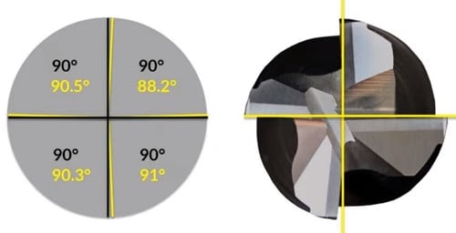
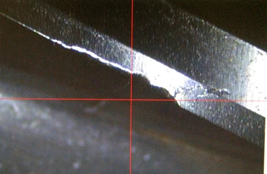
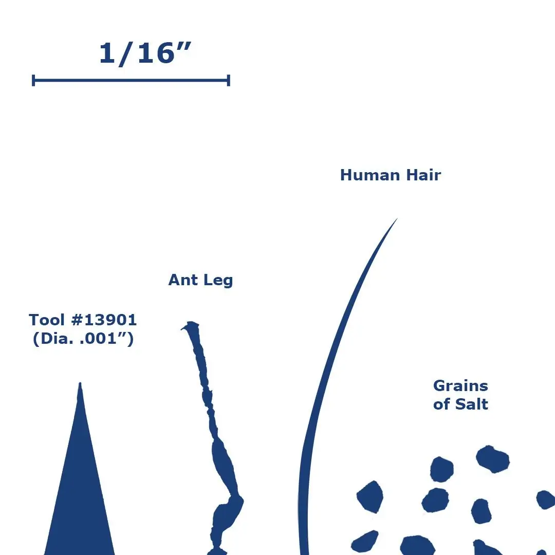
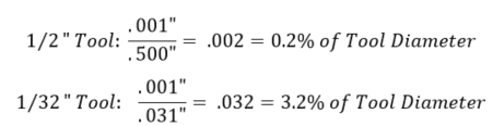
Runout during an operation has a much greater effect on miniature tools, as even a very small amount can have a large impact on the tool engagement and cutting forces. Runout causes the cutting forces to increase due to the uneven engagement of the flutes, prompting some flutes to wear faster than others in conventional tools, and breakage in miniature tools. Tool vibration also impacts the tool life, as the intermittent impacts can cause the tool to chip or, in the case of miniature tools, break. It is extremely important to check the runout of a setup before starting an operation. The example below demonstrates how much of a difference .001” of runout is between a .500” diameter tool and a .031” diameter tool.
Chip Thickness
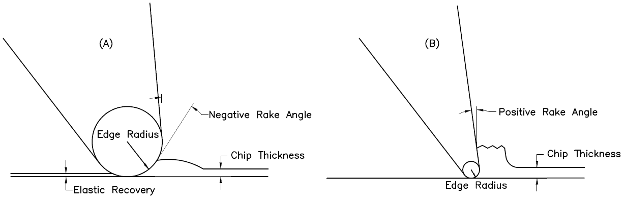
The ratio between the chip thickness and the edge radius (the edge prep) is much smaller for miniature tools. This phenomena is sometimes called “the size effect” and often leads to an error in the prediction of cutting forces. When the chip thickness-to-edge radius ratio is smaller, the cutter will be more or less ploughing the material rather than shearing it. This ploughing effect is essentially due to the negative rake angle created by the edge radius when cutting a chip with a small thickness.
If this thickness is less than a certain value (this value depends of the tool being used), the material will squeeze underneath the tool. Once the tool passes and there is no chip formation, part of the plowed material recovers elastically. This elastic recovery causes there to be higher cutting forces and friction due to the increased contact area between the tool and the workpiece. These two factors ultimately lead to a greater amount of tool wear and surface roughness.
Tool Deflection in Conventional vs. Micromachining Applications
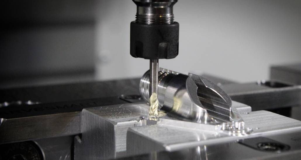
Tool deflection has a much greater impact on the formation of chips and accuracy of the operation in micromachining operations, when compared to conventional operations. Cutting forces concentrated on the side of the tool cause it to bend in the direction opposite the feed. The magnitude of this deflection depends upon the rigidity of the tool and its distance extended from the spindle. Small diameter tools are inherently less stiff compared to larger diameter tools because they have much less material holding them in place during the operation. In theory, doubling the length sticking out of the holder will result in 8 times more deflection. Doubling the diameter of an end mill it will result in 16 times less deflection. If a miniature cutting tool breaks on the first pass, it is most likely due to the deflection force overcoming the strength of the carbide. Here are some ways you can minimize tool deflection.
Workpiece Homogeny
Workpiece homogeny becomes a questionable factor with decreasing tool diameter. This means that a material may not have uniform properties at an exceptionally small scale due to a number of factors, such as container surfaces, insoluble impurities, grain boundaries, and dislocations. This assumption is generally saved for tools that have a cutter diameter below .020”, as the cutting system needs to be extremely small in order for the homogeny of the microstructure of the material to be called into question.
Surface Finish
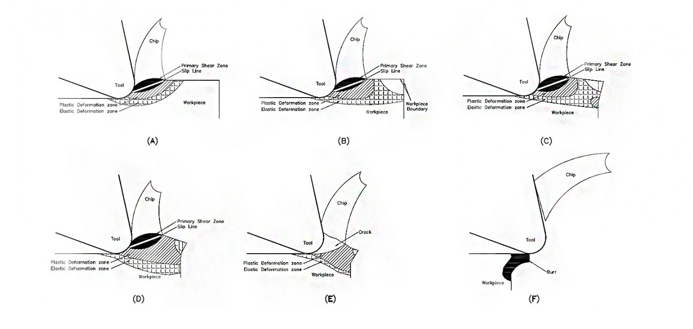
Micromachining may result in an increased amount of burrs and surface roughness when compared to conventional machining. In milling, burring increases as feed increases, and decreases as speed increases. During a machining operation, chips are created by the compression and shearing of the workpiece material along the primary shear zone. This shear zone can be seen in Figure 2 below. As stated before, the chip thickness-to-edge radius ratio is much higher in miniature applications. Therefore, plastic and elastic deformation zones are created during cutting and are located adjacent to the primary shear zone (Figure 2a). Consequently, when the cutting edge is close to the border of the workpiece, the elastic zone also reaches this border (Figure 2b). Plastic deformation spreads into this area as the cutting edge advances, and more plastic deformation forms at the border due to the connecting elastic deformation zones (Figure 2c). A permanent burr begins to form when the plastic deformation zones connect (Figure 2d) and are expanded once a chip cracks along the slip line (Figure 2e). When the chips finally break off from the edge of the workpiece, a burr is left behind (Figure 2f).
Tool Path Best Practices for Miniature End Mills
Because of the fragility of miniature tools, the tool path must be programmed in such a way as to avoid a sudden amount of cutting force, as well as permit the distribution of cutting forces along multiple axes. For these reasons, the following practices should be considered when writing a program for a miniature tool path:
Ramping Into a Part
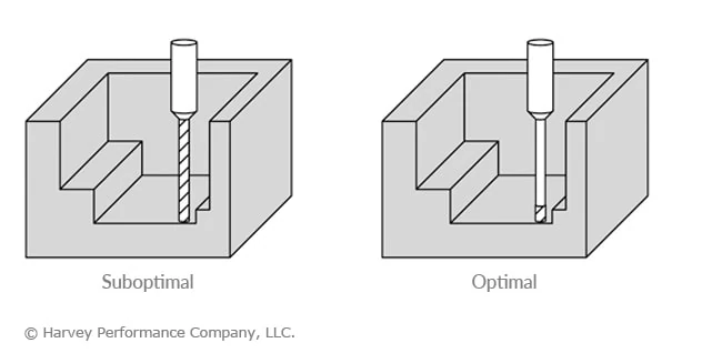
Circular ramping is the best practice for moving down axially into a part, as it evenly distributes cutting forces along the x, y, and z planes. If you have to move into a part radially at a certain depth of cut, consider an arching tool path as this gradually loads cutting forces onto the tool instead of all at once.
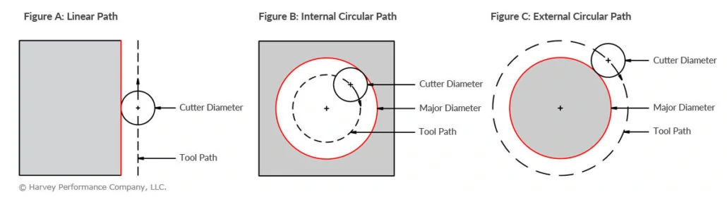
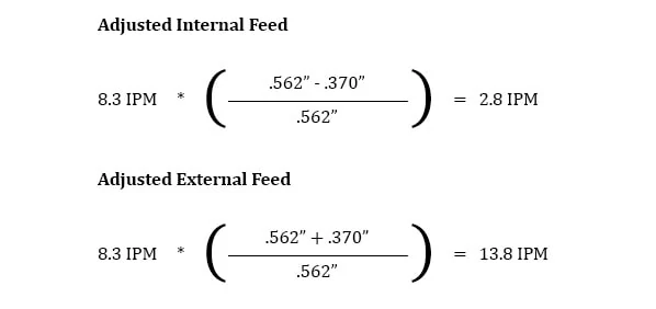
Micromachining in Circular Paths
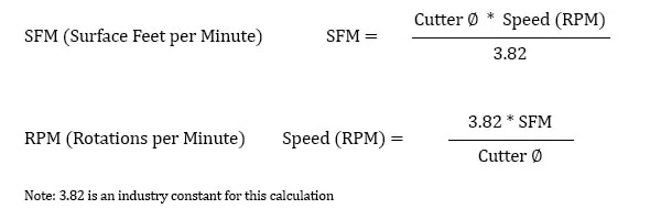
You should not use the same speeds and feed for a circular path as you would for a linear path. This is because of an effect called compounded angular velocity. Each tooth on a cutting tool has its own angular velocity when it is active in the spindle. When a circular tool path is used, another angular velocity component is added to the system and, therefore, the teeth on the outer portion of tool path are traveling at a substantially different speed than expected. The feed of the tool must be adjusted depending on whether it is an internal or external circular operation. To find out how to adjust your feed, check out this article on running in circles.
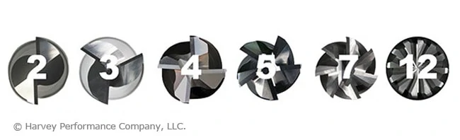
Slotting with a Miniature End Mill
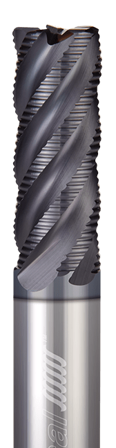
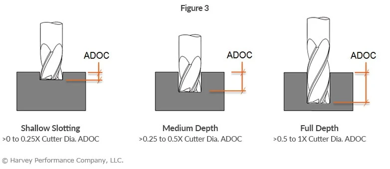
Do not approach a miniature slot the same way as you would a larger slot. With a miniature slot, you want as many flutes on the tool as possible, as this increases the rigidity of the tool through a larger core. This decreases the possibility of the tool breaking due to deflection. Because there is less room for chips to evacuate with a higher number of flutes, the axial engagement must be decreased. With larger diameter tools you may be stepping down 50% – 100% of the tool diameter. But when using miniature end mills with a higher flute count, only step down between 5% – 15%, depending on the size of the diameter and risk of deflection. The feed rate should be increased to compensate for the decreased axial engagement. The feed can be increased even high when using a ball nose end mill as chip thinning occurs at these light depths of cut and begins to act like a high feed mill.
Slowing Down Your Feed Around Corners
Corners of a part create an additional amount of cutting forces as more of the tool becomes engaged with the part. For this reason it is beneficial to slow down your feed when machining around corners to gradually introduce the tool to these forces.
Climb Milling vs. Conventional Milling in Micromachining Applications
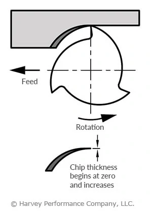
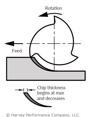
This is somewhat of a tricky question to answer when it comes to micromachining. Climb milling should be utilized whenever a quality surface finish is called for on the part print. This type of tool path ultimately leads to more predictable/lower cutting forces and therefore higher quality surface finish. In climb milling, the cutter engages the maximum chip thickness at the beginning of the cut, giving it a tendency to push away from the workpiece. This can potentially cause chatter issues if the setup does not have enough rigidity. In conventional milling, as the cutter rotates back into the cut it pulls itself into the material and increases cutting forces. Conventional milling should be utilized for parts with long thin walls as well as delicate operations.
Combined Roughing and Finishing Operations
These operations should be considered when micromachining tall thin walled parts as in some cases there is not sufficient support for the part for a finishing pass.
Helpful Tips for Achieving Successful Micromachining Operations With Miniature End Mills
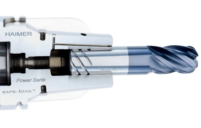
Try to minimize runout and deflection as much as possible when micromachining with miniature end mills. This can be achieved by using a shrink-fit or press-fit tool holder. Maximize the amount of shank contact with the collet while minimizing the amount of stick-out during an operation. Double check your print and make sure that you have the largest possible end mill because bigger tools mean less deflection.
- Choose an appropriate depth of cut so that the chip thickness to edge radius ratio is not too small as this will cause a ploughing effect.
- If possible, test the hardness of the workpiece before machining to confirm the mechanical properties of the material advertised by the vender. This gives the operator an idea of the quality of the material.
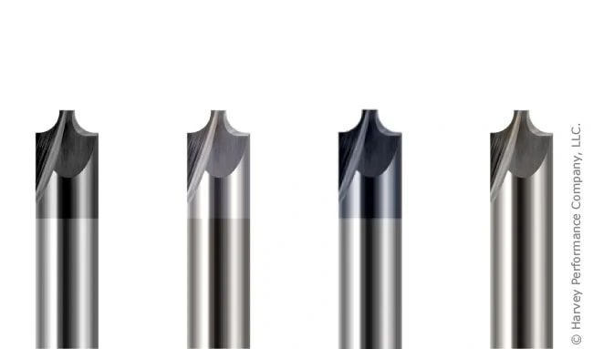
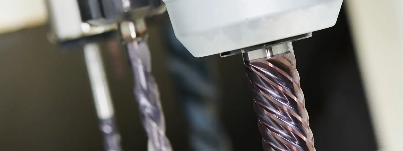
- Use a coated tool if possible when working in ferrous materials due to the excess amount of heat that is generated when machining these types of metals. Tool coatings can increase tool life between 30%-200% and allows for higher speeds, which is key in micro-machining.
- Consider using a support material to control the advent of burrs during a micromachining application. The support material is deposited on the workpiece surface to provide auxiliary support force as well as increase the stiffness of the original edge of the workpiece. During the operation, the support material burrs and is plastically deformed rather than the workpiece.
- Use flood coolant to lower cutting forces and a greater surface finish.
- Scrutinize the tool path that is to be applied as a few adjustments can go a long way in extending the life of a miniature tool.
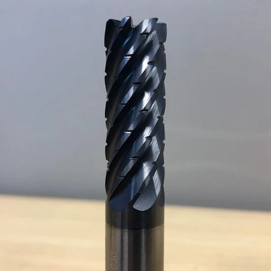
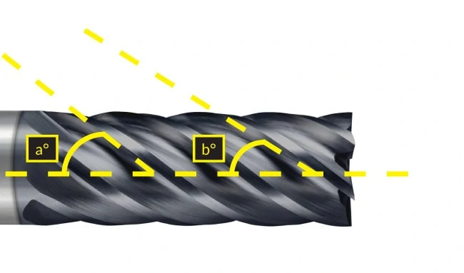
- Double-check tool geometry to make sure it is appropriate for the material you are machining. When available, use variable pitch and variable helix tools as this will reduce harmonics at the exceptionally high RPMs that miniature tools are typically run at.